M47 DRAGON MEDIUM ANTITANK WEAPON SYSTEM
|
|
|
- Brent Sharp
- 5 years ago
- Views:
Transcription
1 HEADQUARTERS FIELD MANUAL (FM 23-24) DEPARTMENT OF THE ARMY M47 DRAGON MEDIUM ANTITANK WEAPON SYSTEM DISTRIBUTION RESTRICTION: Approved for public release; distribution is unlimited.
2 FIELD MANUAL *FM (FM 23-24) NO HEADQUARTERS DEPARTMENT OF THE ARMY WASHINGTON, DC, 30 August 2001 M47 DRAGON MEDIUM ANTITANK WEAPON SYSTEM CONTENTS Preface... iv CHAPTER 1. INTRODUCTION 1-1. Major Components Technical Data CHAPTER 2. OPERATION AND FUNCTION 2-1. Inspection Carrying Techniques Preparation for Firing Firing Positions Target Acquisition and Evaluation Missile Flight and Control Failure to Fire Restoration to Carrying Configuration Adverse Weather Conditions CHAPTER 3. TRAINING EQUIPMENT 3-1. Precision Gunnery Training System Dragon Gunnery Trainer Dragon Field Tactical Trainer CHAPTER 4. UNIT TRAINING 4-1. Training Strategy Commander's Responsibility Training Program Goals Instructor Selection Gunner Selection Matching the Training Program to the Unit Leader Training Gunner Training DISTRIBUTION RESTRICTION: Approved for public release; distribution is unlimited. * This publication supersedes FM 23-24, 3 April Page i
3 Page 4-9. Team Training Collective Training Evaluation CHAPTER 5. INSTRUCTOR'S GUIDE TO EFFECTIVE TRAINING 5-1. Training Program Schedule Individual Instruction Training Sequence Firing Positions M113 Instructional Techniques Sighting, Aiming, and Firing Breath Control Tracking Exercises Range Procedures CHAPTER 6. GUNNER QUALIFICATION PROGRAM 6-1. Requirements Program of Instruction CHAPTER 7. SUSTAINMENT TRAINING PROGRAM 7-1. Gunner Sustainment Training Collective Training CHAPTER 8. EMPLOYMENT Section I. Employment in the Defense Firing Positions Movement Selection of Fighting Positions Preparation of Fighting Positions Preparation of Range Cards Target Identification Target Recognition by Type Thermal Identification Section II. Target Engagement Engagement Range Range Determination Time and Space Vulnerable Points of Armored Vehicles Fire Control Limited Visibility APPENDIXA. TRAIN-THE-TRAINER TASKS FOR THE DGT AND DFTT... A-1 APPENDIX B. DRAGON GUNNERY TRAINER... B-1 ii
4 APPENDIX C. DRAGON FIELD TACTICAL TRAINER... C-1 APPENDIX D. FIRING TABLES FOR DRAGON PRECISION GUNNERY TRAINING DEVICES... D-1 APPENDIX E. M113 ARMORED PERSONNEL CARRIER... E-1 APPENDIX F. SAFETY... F-1 APPENDIX G. GUNNER S PERFORMANCE TEST... G-1 APPENDIX H. DECONTAMINATION AND DESTRUCTION PROCEDURES. H-1 APPENDIX I. THERMAL TARGET RECOGNITION, IDENTIFICATION, AND ENGAGEMENT... I-1 GLOSSARY... Glossary-1 REFERENCES... References-1 INDEX... Index-1 DA FORMS Page iii
5 PREFACE This manual provides guidance for using and employing the M47 Dragon, a mediumrange, antiarmor, surface-attack, guided missile weapon system. It provides information about the M47 Dragon s characteristics, nomenclature, and functions. The training program provided helps develop, evaluate, and maintain the proficiency of Dragon gunners. Tactical employment procedures described herein do not cover all situations. Leaders and members of units equipped with the M47 Dragon should use this manual to train and test individual gunners or teams. This manual also discusses five key elements for maintaining combat proficiency with the Dragon: Technical and tactical information. A training program that stresses command involvement. Centralized training. Gunner selection. Development of qualified trainers. The proponent of this publication is the United States Army Infantry School. Send comments and recommendations on DA Form 2028 (Recommended Changes to Publications and Blank Forms) directly to the Commandant, US Army Infantry School, ATTN: ATSH- INB-O, Fort Benning, Georgia or to lusanoh@benning.army.mil. Unless otherwise stated, whenever the masculine gender is used, both men and women are included. iv
6 CHAPTER 1 INTRODUCTION This chapter describes the M47 Dragon and its components and provides pertinent technical data. The Dragon is a surface-attack, wire-guided, manportable, shoulder-fired, medium antitank weapon system. It can defeat armored vehicles, fortified bunkers, concrete gun emplacements, and other hardened targets. The individual soldier or a two-man team can operate this weapon. Mechanized infantry gunners can use the Dragon with the M175 guided missile launcher mount. This mount provides a stable platform on either the M113 APC or on the M3 or M122 machine gun tripod. The Dragon can engage targets in daylight (with the daysight) and in limited visibility conditions, such as smoke, fog, or darkness (with the nightsight) MAJOR COMPONENTS The Dragon weapon system consists of a daysight, a nightsight, and a round of ammunition. a. Daysight. The daysight is an electro-optical sight that determines the position of the missile relative to the gunner s line of sight (LOS). (1) The daysight generates signals that travel by wire to the missile control system. The missile control system fires the appropriate rocket thrusters to keep the missile heading along the gunner s LOS (Figure 1-1). Figure 1-1. Daysight line of sight. (2) The daysight attaches to and removes quickly from the round (Figure 1-2, page 1-2). The daysight s aluminum housing assembly contains the lens, infrared receiver assembly, and control signal comparator. The firing mechanism, located on the right side of the daysight s housing, consists of a trigger safety plunger and trigger lever bar. A rubber boot seals out moisture from the firing mechanism and safety plunger. (3) A connector cover provides both mechanical and moisture protection for the electrical connector. A lanyard attaches the cover to the daysight. (4) Shock absorbers surround the forward and rear ends of the daysight to protect it and its lens. The lens cover is attached to the daysight by a lanyard. 1-1
7 Figure 1-2. Daysight parts. (5) The daysight s lens is a 6-power telescope. It magnifies the image across a 6-degree field of view (FOV) to help the gunner locate, identify, and track targets. A fitted and molded rubber eye guard protects the gunner s eyes and allows him to adjust rapidly to the sight (Figure 1-3). The infrared receiver consists of an objective lens assembly, graded filter, infrared detector, and nutator mirror. The sensor detects the missile s infrared output while discriminating against background signals. It detects any deviations or excursions of the missile from the gunner s LOS. FOCUS RING EYE GUARD Figure 1-3. Daysight lens and rubber eye guard. (6) The daysight s telescopic lens and infrared receiver align to define the LOS to the target. The tapered cross hair helps the gunner concentrate on the center of his FOV. Then, he can quickly place the cross hairs on the target s center of mass. He uses the stadia lines to determine the range to the target (Figure 1-4). For example, the stadia lines show how large a standard 3-meter by 6-meter Soviet-built vehicle would appear at the Dragon s maximum engagement range of 1,000 meters. b. Nightsight. At dusk, or anytime the light level drops below what is needed to use the daysight, Dragon gunners switch to the nightsight (Figure 1-5). It attaches to the round the same as the daysight. 1-2
8 CROSS HAIRS STADIA LINES RETICLE CROSS HAI RS ALIGNED RANGE MARKS Figure 1-4. Daysight reticle and stadia lines. Figure 1-5. Nightsight. (1) The passive, 4-power AN/TAS-5 nightsight has a 3.4-degree by 6.8-degree FOV. The nightsight is larger and heavier than the daysight. The nightsight converts heat emissions (infrared energy) from a target area into electrical signals, then to visible light (Figure 1-6, page 1-4). This enables the nightsight to display a real-time scene. Objects warmer than the ambient (surrounding) temperature appear in shades of red; cooler objects appear black. Like the daysight, the nightsight monitors the missile and sends commands to keep it on the gunner s line of sight. (2) The firing mechanism, control system, and guidance system are the same as those on the daysight. (3) The externally mounted 4.8-volt DC battery and coolant cartridge enable the nightsight to function without an external power source. If the appropriate accessory equipment is available, the nightsight can use military vehicle power. (4) The nightsight has more controls and operates differently than the daysight. 1-3
9 Figure 1-6. Nightsight s infrared (heat) capability. (a) The ACTUATOR switch (Figure 1-7) turns the system on and off. This four-position switch allows the gunner to evaluate the operating condition of the nightsight. It is normally set to the OFF-LOCK position. Rotating the switch to the AIR-BATT-CHECK position allows the gunner to check the condition of the coolant cartridge and battery. If the indicator light is off and the coolant cartridge and battery conditioner are good, the gunner rotates the switch to the ON position to operate normally. CAUTION Use the fourth position, RELEASE, to release an expended coolant cartridge. (b) The gunner uses the focusing ring to adjust the focus. The brightness (BRT) and contrast (CTRS) controls work the same as those on a television set (Figure 1-8, page 1-5). c. Ammunition. The Dragon s ammunition is an expendable component consisting of both the missile and the launcher itself (Figure 1-9, page 1-6). The missile is installed in the launcher at the factory and is shipped ready to fire. The launcher serves as a storage and carrying case for the missile before it is launched. The Dragon has two types of missiles: the M223 practice round, which has an inert warhead, and the M222 HEAT round. The launcher consists of A smooth-bored fiberglass tube. A breech and gas pressure generator assembly. A wiring harness. A sling. Forward and rear shock absorbers. A sight battery, which provides power to operate the sight and fire the missile. A sight support bracket, which houses the Dragon s electrical connectors. A bipod, which supports the weapon system during dismounted firing. 1-4
10 Figure 1-7. Nightsight actuator switch. Figure 1-8. Nightsight controls. 1-5
11 FORWARD SHOCK ABSORBER TRACKER BRACKET ELECTRI CAL CONNECTOR RACEWAY CONDUIT TRACKER BATTERY REAR SHOCK ABSORBER BIPOD BIPOD RETAINER STRAP CARRYING SLING Figure 1-9. External components of the M222 HEAT (tactical) round TECHNICAL DATA Table 1-1 shows technical data for the Dragon. AMMUNITION M222 HEAT round M223 inert practice round Weight kg (25.29 lb) Missile Length 744 mm (29.39 in) Launcher Length 1,154 mm (44.10 in) Weight 4.70 kg (10.40 lb) Missile Length 846 mm (33.32 in) Launcher Length 1,154 mm (44.10 in) OPERATIONAL CHARACTERISTICS Maximum range Minimum range 1,000 m 65 m DAYSIGHT--Infrared Tracker, Guided Missile, SU-36/P Weight 3.10 kg (6.75 lb) Length 196 mm (7.72 in) NIGHTSIGHT--Night Vision Weight 9.82 kg (21.65 lb) Sight, Tracker, Infrared, AN/TAS-5 Length 368 mm (14.50 in) Table 1-1. Technical data for the M47 Dragon. 1-6
12 CHAPTER 2 OPERATION AND FUNCTION This chapter discusses normal operation and function procedures for the Dragon in the man-portable mode. (For a detailed discussion on the operation of Dragon support equipment, refer to TM ) 2-1. INSPECTION Before placing the Dragon into operation, the gunner visually inspects the Dragon for physical damage and checks its function. During offensive operations, the gunner inspects the Dragon before leaving the assembly area. During defensive operations, the gunner inspects the Dragon before and after preparing the position. (See TM for information about PMCS.) The gunner inspects the daysight, nightsight, and the round CARRYING TECHNIQUES Gunners can use either the long-distance or short-distance carry with the Dragon. a. Long-Distance Carry. The Dragon gunner normally carries the round and the sight separately. This carrying technique is most often used during long-distance moves such as foot marches or cross-country travel, or when contact is not likely. For long-distance travel, the gunner uses carrying technique 1, 2, or 3, as shown in Figure 2-1 (page 2-2). b. Short-Distance Carry. The gunner can carry the Dragon short distances with the sight mated to the round. When using this type of carry, the gunner must keep the forward protective shock absorber and lens covers in place until the weapon is likely to be used. The protective lens covers prevent possible damage to the sight lens and keep foreign objects out of the launcher. Carry technique 4 and 5, also shown in Figure 2-1 (page 2-2), can be used with the round and the sight mated. The soldier should only use one of these carry techniques when firing is likely. Otherwise, he should avoid carrying the weapon system in a ready-tofire configuration PREPARATION FOR FIRING Improper or careless handling of the round can damage its components and cause the missile to malfunction when launched. If there is any reason to believe the missile has been damaged, the round must be returned to the responsible ammunition personnel for inspection and disposition. Before using the nightsight, the gunner must conduct a preoperational check IAW TM a. Releasing the Bipod. Unsnap the bipod-retaining strap (A, Figure 2-2, page 2-3). Push the bipod forward until you feel resistance. Snap off the forward shock absorber. Ensure that the desiccant bag, attached to the forward shock absorber, is not lodged in the launch tube (B, Figure 2-2, page 2-3). While still holding the round, depress the bipod friction lock. Push the bipod legs downward to number 4 or 5, then release the friction lock (C, Figure 2-2, page 2-3). 2-1
13 b. Selecting a Firing Position. Select the firing position that best meets the situation. For training, use the sitting position (discussed later in this chapter). In a combat situation, you can use any one of the three positions: sitting, kneeling, or standing supported Figure 2-1. Dragon carry techniques. CAUTION 1. Do not use the shock absorbers as handles to lift the sight. The shock absorbers might tear off. 2. Do not touch the lenses, as this can easily damage them. c. Removing the Sight from the Carrying Bag or Rucksack. Open the carrying bag or rucksack. Grasp the sight by the trigger mechanism or telescoping barrel. Remove the sight and remove the cover from the electrical connector. Secure the cover to the hook-pile tape on the forward shock absorber. d. Removing the Lens Cover. Secure the lens cover to the top of the forward shock absorber (Figure 2-3). Visually inspect the lenses for damage or obstruction. When using the nightsight, make sure the ACTUATOR switch is in the ON position. 2-2
14 Figure 2-2. Releasing the bipod. Figure 2-3. Cover secured to forward shock absorber. e. Mating the Sight to the Round. Place the sight guide pins in the slots of the sight bracket guide rails (Figure 2-4, page 2-4). This example uses the daysight, but you will use the same procedure for the nightsight. Use both hands and slide the sight firmly to the rear until the spring clip locks the guide pin in place (Figure 2-5, page 2-4). If the sight does not mate, notify your squad or section leader. Assume the firing position and put the round on your shoulder. 2-3
15 WARNING Avoid pressing the safety and the trigger while mating the sight to the round. SIGHT BRACKET Figure 2-4. Aligning the daysight guide pins. Figure 2-5. Seating the daysight on the round. f. Adjusting for Height and a Level Sight Picture. Look through the sight to see if the sight picture is level. An unlevel sight picture (more than 6 degrees off level) will cause the sight to send bad commands to the missile. The missile will fly erratically and the missile will hit the ground. To obtain a level sight picture, adjust the bipod friction lock and the foot adjustment lever (Figure 2-6, page 2-5). 2-4
16 Figure 2-6. Leveling the sight picture FIRING POSITIONS The Dragon can be fired from any one of the three basic firing positions: sitting, standing supported, or kneeling. When the M175 mount is installed on the M3 or M122 machine gun tripods, the gunner can use a modified sitting or standing supported position. Chapter 5 discusses firing positions in detail TARGET ACQUISITION AND EVALUATION After assuming a firing position, the gunner looks through the sight and acquires the target (Figure 2-7). The gunner must evaluate the target to determine whether or not it is within range and engageable. By moving the launcher, the gunner adjusts his sight picture, placing the target within the stadia lines (Chapter 6). a. Acquire and track the target. Figure 2-7. Target acquisition. 2-5
17 b. To fire the weapon, push the safety plunger in with the thumb of the right hand, depress and hold the trigger, and maintain the sight picture until impact (Figure 2-8). When engaging a moving target, move the upper part of your body left or right to adjust for azimuth; move up and down to adjust for elevation. Jerking, bumping, or moving the sight while the missile is in flight may cause you to miss the target. To establish a smooth tracking rate, track the target for about two seconds before squeezing the trigger. c. Ignore the missile when it appears in the sight picture. Do not try to fly the missile. Keep the cross hairs on the target let the sight guide the missile. Figure 2-8. Correct sight picture MISSILE FLIGHT AND CONTROL As the missile leaves the launch tube, the infrared flares begin to operate, and the commandlink wire is dispensed from the missile. The missile fins fold out and lock into place. The safety and arming device sequence is completed after the missile has traveled about 65 meters (Figure 2-9). INFRARED FLARE SIGNALS FIN ASSEMBLY ROLL SAFE and ARMING GUIDANCE WIRE ROCKET THRUSTERS Figure 2-9. Dragon functioning concept. a. The sight s electronic controls compare the missile s position with the gunner s LOS. It sends electronic position information to the missile through the command-link wire. b. Based on information received from the sight, the missile generates commands to correct its position. The missile may store the commands until it rolls to the proper position 2-6
18 for its rocket motors to fire, or it may fire the rocket motors immediately to correct the missile s position relative to the gunner s LOS. c. The missile s rocket motors fire to accelerate it or to correct its position. The gunner keeps the cross hairs on the selected aiming point until impact. d. To fire a second round, the gunner releases the spring clip at the rear left side of the sight support assembly, slides the sight forward, and lifts it clear of the support. The gunner expends or destroys and discards the round IAW unit SOP. The gunner either prepares another round or he secures the sight and any extra rounds and prepares to displace on order FAILURE TO FIRE A failure to fire occurs whenever the missile does not leave the launcher after the gunner depresses the trigger lever bar. When the missile fails to fire, the gunner immediately resqueezes the trigger lever bar and continues to track the target for 15 seconds. If after 15 seconds the missile has not fired, the gunner announces Misfire, releases the trigger lever bar, and carefully feels near the sight battery. If the sight battery is hot, the gunner performs hangfire procedures; if it is cold, the gunner performs misfire procedures. Ideally, a two-man team operates the Dragon, and the assistant gunner secures the new round. In the normal tactical situation, a moving armored vehicle closes on the position and moves to within 1,000 meters. To preserve forces, leaders should have an emergency action SOP in place that covers what to do if a Dragon fails to fire. WARNING A hangfire is a delayed firing. It is difficult to distinguish immediately from a misfire. The difference lies in when they occur and what causes them. A misfire occurs when a gunner tries to fire a round from a cold weapon and the round jams for mechanical reasons. A hangfire occurs when a round jams in a hot weapon. a. Hangfire Procedures (Combat Only). In a typical tactical situation, a moving armored vehicle closes on the position and moves to within 1,000 meters. (1) Remove the sight from the round and place it on the ground away from the firing site. Keep the round pointed toward the enemy; advise nearby soldiers of the round s failure to fire. (2) Obtain a new round and mount the sight to it. (3) Acquire the previous target and continue with the mission. b. Hangfire Procedures (Training Only). (1) The gunner notifies the range officer or NCOIC about the hangfire. (2) The gunner removes the round from his shoulder and places the round flat on the ground. The gunner ensures the bipod legs are pointing to the side, with the round pointing downrange. 2-7
19 (3) The gunner moves away from the position. (4) The range officer or NCOIC clears all personnel within 50 meters of the round and notifies the EOD. c. Misfire Procedures. (1) Loosen the sight from the round, then remate it to the round. (2) Track the target and try to fire again. (3) If the round again fails to fire, feel carefully near the sight battery once more. (4) If the battery still feels cold, remove the sight from the round. Place the round on the ground away from the firing site. Keep the round pointed toward the enemy; advise soldiers near you of the misfire. (5) Mount the sight on another round and continue with the mission. (6) If the new round also fails to fire, carefully feel near the sight battery. If that battery is also cold, the sight is probably defective. (7) If you can find another sight, replace the existing sight and continue with the mission, using previously unfired rounds RESTORATION TO CARRYING CONFIGURATION The gunner uses a long-distance or short-distance carry to move a Dragon round that he has prepared for firing but that he no longer needs. To use the long-distance carry, the gunner performs Steps 1 and 2. To use the short-distance carry, the gunner performs only Step 2. a. Step 1. Remove sight from round. (1) Replace sight lens cover. (2) Remove sight from round; and replace connector cover on sight and round. (3) Return sight to carrying bag or rucksack. b. Step 2. Restore round to carrying configuration. (1) Replace connector cover. (2) Replace forward shock absorber. (a) Set round in an upright position with rear shock absorber resting on the ground. (b) While lightly pushing down on bipod, press bipod brace toward round to lift it from locking slot. (c) Once bipod brace is unlocked, push down on bipod until upper part of bipod that attaches to round is parallel with muzzle of launcher. (d) Align cutout portion of forward shock absorber with bipod at launcher muzzle. (e) Push down on shock absorber while lowering bipod against round. Ensure upper part of bipod engages shock absorber. (f) Retract bipod legs and secure them to round with retainer strap. (3) Lift up on forward shock absorber to ensure it is secure. Round is now in safe carrying configuration ADVERSE WEATHER CONDITIONS If the gunner can see the target, the Dragon can operate in all weather conditions. The Dragon and round stay the same temperature. For example, if the gunner removes a Dragon from a vehicle whose inside temperature is 45 degrees Fahrenheit, both the Dragon and the 2-8
20 round will measure 45 degrees Fahrenheit, even if the outside temperature measures 32 degrees Fahrenheit. a. Cold Weather. Before deployment, check all optical surfaces and all mechanical devices for proper operation. Ensure there is neither ice nor snow on the sight components. Never operate the Dragon in temperatures below minus 25 degrees Fahrenheit. b. Hot Weather. To avoid subjecting the round and sight to prolonged, direct sunlight, provide as much shade or cover as possible. Never operate the Dragon in temperatures above 145 degrees Fahrenheit. 2-9
21 CHAPTER 3 TRAINING EQUIPMENT Training equipment provides units with a low-cost means to develop and maintain gunnery skills. To train effectively, trainers must know the weapon and the training equipment. This chapter describes Dragon training equipment and provides a program to train instructors to use it. (Appendix A provides train-the-trainer tasks for the DGT and DFTT.) 3-1. PRECISION GUNNERY TRAINING SYSTEM The Dragon PGTS includes one indoor training system and one outdoor training system. The Dragon gunnery trainer (DGT) is the indoor training system. It provides a means for precision gunnery training, practice, and qualification with the Dragon. The Dragon field tactical trainer (DFTT), the outdoor training system, provides a means for familiarization with the Dragon. (Appendix B and Appendix C discuss the DGT and DFTT, respectively.) a. The realistic training offered by the Dragon PGTS allows units to achieve a high level of proficiency without firing live Dragons. Individual units are responsible for conducting sustainment training on the Dragon PGTS. b. Soldiers can obtain instructional videotapes on the Dragon PGTS from training support centers (TSCs). Basic instructional fire (Firing Tables 1 through 4) is conducted on the DGT. These tables introduce new gunners to the basic gunnery skills required to engage targets with a Dragon. Firing Tables 5 and 6 are conducted in a simulated outdoor tactical situation using the DFTT. Firing Tables 7 and 8 are conducted on the indoor DGT. Firing Table 7 allows gunners to practice for qualification. If they score 16 out of 20 on Firing Table 8 (Table 3-1), gunners qualify on the Dragon. (Appendix D describes firing tables and provides examples of completed firing tables.) FIRING TABLE NUMBER PURPOSE OF FIRING TABLE TRAINING DEVICE PAGE IN MANUAL Familiarization DGT D-1 Familiarization DFTT D-2 7 Practice for qualification Qualification 8 (Hit 16 out of 20) DGT D-3 Table 3-1. Firing tables for Dragon training devices. 3-1
22 c. Train-the-Trainer Program. A successful Dragon training program requires welltrained NCOs who know and have confidence using both trainers. Each company should have at least one certified trainer. (Appendix A provides train-the-trainer tasks for both the DFTT and the DGT.) 3-2. DRAGON GUNNERY TRAINER The DGT man-portable trainer simulates the Dragon guided missile system's sight(s), controls, switches, and indicators. (See Appendix B for a complete description of the DGT and its components.) Training programs selected by the training NCO display simulated battlefield scenes through the sight. These scenes include both enemy and friendly vehicle targets. The indoor, 110- or 220-volt AC Dragon gunnery trainer enables units to train personnel on the Dragon without a range or training area (Figure 3-1). a. Role. Soldiers train on the DGT to Assume the correct Dragon firing position. Identify targets. Determine engageability of targets. Engage targets (including tracking and firing). b. Missions. Matched sets of videodiscs and floppy (data) disks provide a library of missions. Each disk set contains 30 missions of various lengths plus learning objectives. Each mission applies to both daysight and nightsight viewing. c. Target Options. The DGT allows the trainer to adjust the difficulty of the scenario to the shooter's skill. To do this, trainers can Change the target kill zone. Change the obscuration. Vary the amount of weight the system loses after a round is fired. Select night fire. Select multiple or moving targets. Figure 3-1. Dragon gunnery trainer. 3-2
23 d. Feedback. The DGT enables the trainer to provide visual feedback to the firer in either of two ways. He can replay the mission on video, or he can print out two views (from the top and side) of the actual mission. Both show horizontal and vertical tracking errors and the firer's score. Figure 3-2 shows the instructor's console. Figure 3-2. Instructor's console, Dragon gunnery trainer DRAGON FIELD TACTICAL TRAINER The DFTT outdoor trainer realistically simulates the appearance, feel, launch, flight, and effects of the Dragon guided missile system. (Appendix C describes the DFTT and its components.) Training with the DFTT can occur on designated ranges, general outdoor areas, or representative tactical environments. The DFTT uses the Dragon daysight or nightsight and trainers can use it instead of the inert practice round. The DFTT is bipodmounted, just like an actual Dragon. a. Role. Trainers use the DFTT to familiarize gunners with firing the Dragon in an outdoor environment. Specifically, they use it to train soldiers to Assume the correct Dragon firing position. Determine engageability of targets (whether targets can be engaged). Engage targets (including tracking and firing). b. Targets. Each target has a retroreflector. This acts as a mirror and returns part of the laser beam sent by the trainer round. The DFTT transmits Dragon MILES code, so it can also kill targets equipped with a MILES (multiple integrated laser engagement system) harness, as long as the target also has a retroreflector. 3-3
24 CHAPTER 4 UNIT TRAINING This chapter guides the unit leader in developing a successful unit training program TRAINING STRATEGY A training strategy is the overall concept for integrating resources to train the skills individual and collective needed to perform a unit's wartime mission. Commanders at TRADOC institutions as well as in the units themselves implement the Dragon training strategy, whose four parts include initial training, sustainment and advanced training, collective training, and leader training. Commanders make sure that they include trainer certification as part of the overall training strategy. Using this manual, a unit commander can develop an effective Dragon training program that meets unit requirements. a. Initial Gunner Training. Initial gunner training is a prescribed POI conducted in TRADOC institutions. Initial gunner training includes 15 blocks of instruction. To pass, the soldier must successfully achieve a score of 16 out of 20 engagements on the DGT and successfully complete the 11 tasks in the gunner's performance test. (Chapter 6 provides an example POI.) b. Sustainment and Advanced Training. Sustainment and advanced training are conducted in the unit. (1) Sustainment Training. Sustainment training, conducted monthly, quarterly, and annually, ensures gunners retain the skills they learned in initial training. To retain their skills, gunners practice precision tracking on the DGT at least monthly. To practice, they fire selected engagements from the monthly sustainment table using the DGT and DFTT. They must also complete at least 50 percent of the gunner's skill test. (Chapter 7 discusses sustainment-training programs in detail.) (2) Advanced Training. The unit conducts advanced training. It consists of tracking exercises using the DGT, DFTT, or the Dragon MILES. The tracking engagements grow more difficult. Existing conditions, equipment, or tactical play determine difficulty. Examples of advanced training include Night tracking exercises using artificial illumination or the AN/TAS-5 nightsight. MOPP tracking exercises. Other situational gunnery exercises. c. Live-Fire Training. The number of live missiles the gunner may fire depends on the type of unit and on budget constraints. The unit may conduct annual live fire in an instructional setting or may integrate it into other live-fire exercises. Where possible, live missile firings should closely follow a scheduled qualification. Only currently qualified gunners should be allowed to fire live missiles. d. Collective Training. The unit conducts collective training to fully integrate the Dragon into the unit's overall combat power. Collective training has two parts: force-onforce training and live fire training. (1) The unit conducts force-on-force training with MILES during a squad and platoon FTX or STX. During semiannual external evaluations, the unit evaluates the platoons on Dragon employment. 4-1
25 (2) The unit conducts live-fire training using the laser target interface device (LTID) or actual missiles (live or inert) along with platoon LFXs. Dragon gunners or teams should participate in squad or platoon collective live-fire exercises at least twice a year. e. Leader Training. Leader training occurs in the unit through NCO and officer development classes and personal initiative. Leaders selected as Dragon instructors must have already demonstrated proficiency in using the Dragon and should periodically recertify to maintain leader proficiency COMMANDER'S RESPONSIBILITY The commander plans, executes, and supervises training, selecting instructors and gunners based on the criteria in this chapter. He makes sure that instructors and gunners receive training. The commander does the following: a. Allows adequate time for effective training. b. Ensures all training meets training standards. c. Combines Dragon training with other unit tactical training. d. Ensures the maintenance facility properly maintains all consolidated Dragon training equipment. e. Conducts sustainment training. f. Ensures subordinate leaders conduct operational readiness checks. g. Periodically inspects all tactical and training equipment. h. Keeps a formal record of Inspections. Training results. Gunner qualifications. Gunner turnover. i. Evaluates the Dragon training and corrects deficiencies in future training TRAINING PROGRAM GOALS Training program goals provide leaders with the objectives necessary for success. For soldiers to achieve proficiency in Dragon gunnery, leaders must Train them to successfully engage armored targets. Train them to maintain and operate the Dragon and related training devices. Provide clear sustainment training standards. Make sure gunners know how to meet the standards. Train gunners to those standards. Conduct sustainment training. Evaluate each gunner's performance INSTRUCTOR SELECTION Dragon instructors have to meet the same standards that gunners do. The commander picks soldiers who want to and can instruct and who have a high level of tactical competence at squad and platoon levels. Experience as a Dragon gunner will serve an instructor well, but 4-2
26 does not guarantee a soldier s success as an instructor. Finally, the overall training strategy must include trainer certification GUNNER SELECTION First, the leader identifies soldiers who want to be Dragon gunners. Then, he makes sure each soldier closely approaches the physical standards for Dragon gunners shown in Table To track moving targets, the soldier must be able to flex his upper trunk to the left and right. 2. To hold the weapon steady during tracking and to carry it as required, a soldier must have considerable upper body strength and physical stamina 3. To use the Dragon, a soldier must stand between 5 feet tall and 6 feet 2 inches tall the bipod only adjusts for this height range. 4. To acquire a target, fire the Dragon, and track the round, a soldier must show that he can hold his breath for at least 13 seconds. 5. To use the Dragon, a soldier must have unaided minimum vision of 20/100, correctable to 20/20. The focus (reticle adjustment) can only compensate for this amount of nearsightedness. 6. To use the Dragon, a soldier must have right-eye dominance. He must be able to close his left eye independently. That allows him to keep his left eye closed to protect it from distracting dust and debris. Table 4-1. Physical standards for the Dragon gunner MATCHING THE TRAINING PROGRAM TO THE UNIT Mandatory training programs seldom fit a unit's particular circumstances and needs. Only the unit's own commander can develop its training program. Table 4-2 shows the steps for developing a unit-training program. The key is to consolidate training at unit level. For this to succeed, the commander must Assign a qualified NCO with additional duties as NCOIC of Dragon training. Include Dragon training on both short-range and long-range training calendars. Hold subordinate leaders accountable for execution of training LEADER TRAINING Each commander must determine what specific, Dragon-related tasks he and other leaders must perform. Then he develops these tasks into training objectives. Next, instructors choose proper training methods, depending on the resources available and other training 4-3
27 requirements. If incoming leaders do not know how to employ the Dragon, the commander makes sure they receive Dragon training from the basics on up through the more difficult tasks. Initial Dragon training works well in the classroom, since it depends on the use of lectures, seminars, small discussion groups, and briefings. This cuts down on the use of expensive training resources such as ranges and transportation. 1. Identify all the unit's tactical and administrative missions. 2. Analyze the unit's missions. Determine what individual and unit tasks soldiers must accomplish in order to complete the mission. 3. Establish individual and unit training objectives to accomplish the unit's tasks. 4. Determine the level of individual and unit proficiency in the unit's tasks. 5. Determine individual and unit training needed to attain the training objectives. 6. Identify available training resources. 7. Program and schedule training based on the training resources available and on individual and unit training needs. 8. Conduct training. 9. Monitor and evaluate training, and revise the training program as required. Table 4-2. Steps in developing a unit training program GUNNER TRAINING Dragon gunners should be trained consistently and as repetitively as resources allow. All training includes gunnery and night fire. a. Training Methods. Two main methods are used to train the Dragon gunner: (1) Centralized Gunnery Training. Centralized gunnery training requires the unit to train all Dragon gunners at once. Training type depends on the training resources available (equipment, facilities, personnel, and time) and the tasks to be taught. (a) Equipment and Facilities. Limited distribution of training equipment suggests centralized control of training at the highest unit level possible. Also, the number of firing ranges suitable for the Dragon may dictate centralized control over these facilities. (b) Personnel. A shortage of qualified Dragon instructors can hamper gunnery training. (c) Time. Centralizing Dragon training can save training time since fewer instructors and classes are required. For example, if the training is centralized at brigade level or higher, battalion and company level instructors can focus on other training requirements. With 4-4
28 centralized training, qualified Dragon instructors prepare and conduct training. They need less time to prepare than would unqualified instructors. (d) Tasks. When considering centralized training, the commander also considers the task he wants to train. If the task relates to gunnery training or qualification, the number of training sets and ammunition available might limit the choice to centralized training. Dragon gunners first learn how to prepare a basic range card. Then they practice applying what they have learned using different pieces of terrain or terrain substitution (maps, sand tables, or 35- mm slides of the terrain). Gunners build these skills by working in small groups where they can ask questions, talk about the answers, and debate the advantages and disadvantages of the range cards. (2) Round-Robin Training. Battalions have a limited number of training sets, so soldiers cannot practice all at once. Rather than letting a few soldiers practice on the equipment while others watch, trainers can set up round-robin (multistation) training. Soldiers then rotate through the stations. This keeps everyone actively engaged in training the whole time. For example, soldiers might train on the equipment itself at Station Number 1, learn to prepare range cards at Station Number 2, and learn to identify enemy vehicles at Station Number 3 (Figure 4-1). Figure 4-1. Example of round-robin training. b. Gunnery. Gunnery qualifies gunners to fire the Dragon tactically and nontactically. To qualify, gunners must meet the following objectives: (1) Detect vehicles at different ranges under varying field conditions, such as rolling hills and vegetation, with the vehicles moving and stationary. (2) Determine whether a moving target, if engaged, will reach cover before impact. (3) Prepare a firing position and range card. (4) Know how to lessen the signature of the backblast. 4-5
29 (5) Know what suppressive fires the enemy can place on the firing position. (6) Know how to use cover and concealment, deception, surprise, and movement. (7) Know unit SOPs covering rules of engagement, including signals to lift or shift fires, priority of targets, and times to engage targets. (8) Know where to obtain resupply of missiles. (9) Know how to inspect the round before firing. c. Night Training. Since threat doctrine stresses night operations, gunners should practice their skills at night. They can do this during FTXs, with the gunners using the FHTs with nightsights, or they can do it on a range, under controlled conditions, with artificial illumination TEAM TRAINING Due to the frequent need for leaders to employ Dragons as part of a team, team training must become an integral part of Dragon training in the field. As a rule, Dragon gunners employed apart from their squad positions have at least one assistant gunner and ammunition bearer with them, or they may be employed in an antiarmor fire team. The other members of the team work with the gunner as a coordinated element. As such, their duties include providing security for the gunner, helping the gunner prepare his firing position, carrying ammunition (missiles), and locating targets. a. Once gunners have qualified with the Dragon, and once leaders have trained in tactical employment of the Dragon, they can train together profitably in FTXs. (1) During their training, leaders must decide how to employ the Dragon. They could use scenarios, simulated threat conditions, or OPFOR, for example. Based on these simulated conditions, platoon leaders practice choosing armor avenues of approach, selecting Dragon firing positions, and making related employment decisions. (2) Leaders should have gunners prepare firing positions and range cards, and simulate engaging targets. Employing gunners with their squads helps train the other squad or fire team members to perform their duties (providing security, locating targets, and so forth). Then, leaders should evaluate and discuss the training exercises to decide if the techniques and tactics used were the best ones for the situation. b. When qualifying on the range, Dragon gunners usually learn under near ideal conditions: They have excellent fields of fire and a target that moves conveniently back and forth on level ground directly in front of them. Except when other gunners fire, they have no distractions. So, after qualifying on the range, they are ready for more advanced training. This means using the Dragon under more realistic, and therefore more difficult, conditions, which the commander creates. The following paragraphs suggest a few ways to add realism to Dragon training: (1) During both FTXs and practice firing exercises on the range, train the gunner to concentrate while tracking a target. Try to distract him with various combinations and amounts of smoke, haze, and harassing fires. Detonate explosives near him to simulate the noise of enemy artillery and tank fires. To simulate nearby explosions, detonate explosives under a bag of flour. Obscure the target with smoke in or near the gunner's position or target this makes tracking more realistic. (2) During MILES-Dragon tracking exercises, the target vehicle with the MILES receivers must travel over various terrain. This moves the target across the front or towards 4-6
30 the gunner's position over various terrain such as curving roads, or wooded or rolling terrain COLLECTIVE TRAINING In addition to monthly or quarterly training and qualification (or both), Dragon gunners must demonstrate their proficiency during squad and platoon exercises. Each Dragon gunner takes part in live-fire exercises as part of a squad or larger unit. He does the same in a platoon external evaluation based on standards in ARTEP 7-8-MTP (RDL version). In live-fire exercises, the unit uses actual Dragon rounds or LTIDs with other small-arms targets. Platoon external evaluations should include medium antiarmor weapons tasks and should be conducted as part of a company FTX or STX EVALUATION One of an instructor's major responsibilities is to evaluate training. The training to be evaluated may be training that the instructor conducted or training that was conducted by another instructor. The evaluation is concerned with the effectiveness and efficiency of training. a. Training effectiveness refers to whether the soldiers, teams, or units met the standards established in the commander's training objective(s). b. Training efficiency refers to how well instructors used the available training resources. Leaders should write all evaluations in the AAR format. This helps make sure that gunners remember what they learned from their mistakes. It also helps trainers improve future training. 4-7
31 CHAPTER 5 INSTRUCTOR'S GUIDE TO EFFECTIVE TRAINING This chapter provides the instructor with the information needed to train and sustain Dragon gunners and to train soldiers as team members TRAINING PROGRAM SCHEDULE The number of firing sites that can be staffed with instructors and equipped with DGTs and DFTTs dictates the number of gunners for each class. This allows for the effective use of time. a. Instructors must allow sufficient time to orient students on the equipment. Negative results occur when the training schedule is shortened. The more information each soldier receives about how the weapon and training equipment operate and on the purpose of each, the better the soldier will perform as a gunner. b. Initial marksmanship training, in the institution or unit, teaches essential skills and develops fixed and correct procedures in marksmanship before range practice begins. Thoroughly instructing and carefully supervising practice in the initial phase saves time and ammunition during range firing. It also allows students to develop techniques and procedures necessary for well-trained Dragon gunners and teams INDIVIDUAL INSTRUCTION To prepare for live firing the Dragon, each gunner must learn various skills and habits. Although the Dragon training equipment closely simulates firing the Dragon weapon, gunners require personalized individual instruction to develop proper gunnery techniques and procedures. Instructors should key on the following points: Coach and stress the gunnery techniques shown in Table 5-1. Use and emphasize the sitting position and standing supported positions. Have gunners practice tracking in both directions left to right and right to left. Have gunners clean the training equipment at the end of the day. Tight eye contact with the eyepiece. Proper position. Steady hold at the launch. Steady tracking at all times, especially through smoke. Slow and steady aim point correction to the target. Table 5-1. Gunnery techniques TRAINING SEQUENCE The Dragon gunner should receive training in the following sequence to control the missile launch and flight: Positions. Sighting, aiming, and firing. 5-1
32 Breathing. Tracking exercises. Qualification and verification FIRING POSITIONS The gunner must acquire and maintain a stable body position relative to the weapon and be able to move smoothly when tracking a moving target. The round must be solidly anchored on the muscle of the gunner's shoulder. His arms and hands must be properly placed to squeeze the trigger and to maintain the stability of the round. The position of the eye against the eyepiece is critical. Keeping the eye firmly pressed into (against) the eyepiece reduces launch-induced movement and prevents obscuration. The three basic firing positions for the Dragon are the sitting, standing supported, and kneeling. The gunner uses a modified sitting position to fire the Dragon from the M175 mount. The M175 mount fits the M3 or M122 machine gun tripod. (For more information about use of the tripod, see Appendix E.) a. Sitting Position. Demonstrate the sitting position, then have the soldiers assume the position also (Figure 5-1). Instruct them as follows: (1) The sitting position is the most stable. Sit with your legs extended as far as possible. Place the notch of your boot heels on the bipod and push outward. Figure 5-1. Sitting position. 5-2
33 (2) Lean forward from your waist as far as possible. Pick up the round and place it on the muscle portion of your shoulder, keeping it tight against the curve of your neck (Figure 5-2). Figure 5-2. Position of round on shoulder. (3) Grasp the barrel of the sight with your left hand, curling your thumb under the tube. Grasp the firing mechanism with your right hand, with your thumb on the safety, three fingers on the firing lever, and your little finger on the front of the firing mechanism. Place the heel of your hand on the base of the firing mechanism to provide a firm grip and reduce slippage. When firing, hold the trigger in the depressed position; if you release your hand, you will experience an involuntary muscle reaction that will affect the sight and in turn the path of the round. (4) Lift your head to align your right eye with the telescopic sight. Press your head forward and press your eye firmly against the eye guard. This forces your eye to stay open. Close your left eye, and keep it closed. If necessary, focus the sight. (5) Pull down and back with your hands while pushing out with your feet. Try to touch your elbows together and to your chest at the same time (Table 5-2). (6) Keep your back as straight as possible while leaning forward for better breath control. This limits discomfort and increases your ability to move your upper body. 5-3
34 (7) Maintain arm, back, and leg muscle tension. Use enough force that you do not experience an involuntary muscle reaction when the weight of the missile is removed from your shoulder. 1. Stress the need for keeping the pull-down force on the sight and the eye tight in the eye guard. 2. Body position and breath control are the two key elements to effectively engage targets. 3. Ensure the gunner keeps his body and limbs clear of the backblast area. He must keep the round at least 6 inches off the ground in order for the missile fins to clear the ground. Table 5-2. Training notes. b. Standing Supported Position. Demonstrate the standing supported position, then have the soldiers assume it also (Figure 5-3, page 5-4). Instruct them as follows: (1) While standing in an individual fighting position or behind a support, place the bipod legs to your front. Place it at such a distance that you must reach for the round. (2) Spread your legs a comfortable distance apart, keeping them straight. Place the round on your shoulder muscle. (3) Lean forward against the wall of the fighting position to support your body from the waist down, so that you are in a stable firing position. (4) Grip the sight as you did in the sitting position. Pull backward and down, while straightening your upper body slightly; this removes any slack in the bipod. (5) Place your upper body, arms, hands, head, and eyes in the same position as you did when you assumed the sitting position. c. Kneeling Position. Kneel, and spread your knees a comfortable distance apart. Position the bipod so that you have to lean forward to position your eye in the eye guard (Figure 5-4). Grasp the sight as previously described. Assume the same upper body position you did for the other firing positions. Place the round on your shoulder muscle, keeping it tight against your neck. As you lower your buttocks to your heels, take the slack out of the bipod. Try to sit on your heels so you will have a stable firing platform. 5-4
35 Figure 5-3. Standing supported position (fighting position). Figure 5-4. Kneeling position M113 INSTRUCTIONAL TECHNIQUES Certain instructional techniques apply only to M113-equipped units. (See Appendix E for more information.) 5-6. SIGHTING, AIMING, AND FIRING Once the gunner has mastered the firing positions, the instructor can teach him how to sight, aim, and fire properly. a. Sighting. Place the eye in the eyecup and pull the weapon tight enough against your eye that you cannot blink. Wrap your small finger around the front of the firing mechanism to add pulling force and to help keep the weapon tight against your eye. Visually select a target, and then acquire it through the daysight or nightsight by adjusting the upper portion of your body. (1) Keep the weapon tight to keep the sight picture. (2) Do not move your eye in the eyecup. If you move your eye, you will see the side of the telescope prism, which will blur your sight picture. b. Aiming. Confirm that the target is within range by using the stadia lines. Place the cross hairs of the sight on the center of the target's visible mass. Regardless of the target's range or speed of movement, keep the cross hairs on the firing point until after you have fired and observed the impact of the round. To maintain the proper sight picture on a moving target, you have to move the upper portion of your body laterally (sideways). When you fire 5-5
36 from a seated position, never rest your elbows on your knees. This transfers any movement of your leg directly to the sight. c. Firing. Fully depress the safety before you try to squeeze the trigger. Then, squeeze do not pull the trigger. Since the Dragon has little recoil, many gunners move more when they pull the trigger than when they experience the missile's launch effects (recoil and backblast) BREATH CONTROL Aiming the Dragon is similar to aiming a rifle, except that the cross hairs must be kept on the desired impact point for 1 to 12 seconds following missile launch, depending on range to the target. Training must stress the importance of starting to hold the breath two seconds before squeezing the trigger and continuing to hold it while acquiring the target, firing, and tracking. That is, to prevent breathing from interfering with tracking, the gunner takes a breath and holds it while pressing the trigger. He must not breathe while tracking a target, because body movements cause the launcher to move. To check for breath control, the instructor watches the gunner's back TRACKING EXERCISES Reacting properly to temporary obscuration is an important gunner skill. Occasionally, the target may be obscured by launch gases, dust, and so forth. The gunner's instinctive reaction is to look for a target. This can either cause erratic missile flight, or it can terminate the flight. Training prepares the gunner to "freeze" on a stationary target or to continue tracking at the established rate on a moving target until the target reappears. Instructors should simulate obscuration during DGT and DFTT exercises. They should show soldiers how an improper reaction causes the LOS to move outside the established aiming error limits. Most training should be conducted at moving targets to promote gunner concentration. A gunner who can hit a moving target consistently can hit a stationary target easily. Most misses occur on moving targets. Training in the tracking of a moving target should begin when a gunner achieves proficiency in assuming positions, sighting and aiming, and breathing RANGE PROCEDURES Leaders normally consolidate qualification, verification, and sustainment range firing for gunners and assistant gunners at battalion or higher. a. Officer or NCOIC. Table 5-3 (page 5-6) shows officer or NCOIC duties. (See also Appendix F.) 5-6
37 Organizes the range. Assigns, coordinates, and supervises the firing lines. Issues fire commands and general instructions to the firing line. During all firing exercises, enforces safety precautions as prescribed in AR , local SOPs, and applicable range regulations. Stresses precision, a steady tracking rate, point training, and use of a firm firing position posture in all instructional firing. Fires exercises in the order listed in the firing tables. Ensures that instructors control the exercises using appropriate fire commands. Ensures that a qualified instructor inspects all DGTs, DFTTs, and sights before and after each firing day for cleanliness, serviceability, and operation. Instructs gunners and assistant gunners on duty assignments and range operating procedures before training them with the equipment. Divides them into teams and assigns each of them a position. Table 5-3. Officer or NCOIC duties. b. Qualification Training. For qualification, the gunner must fire the DGT. c. Verification Training. A gunner must verify quarterly to meet qualification standards. d. Sustainment Training. For monthly sustainment training, see Table 5-4 (page 5-7). The commander can select any target speed and monitor DFTT operation for gunner proficiency. e. Coach and DFTT Operator. During instructional firing, a coach or DFTT operator is at each DFTT to instruct and assist the gunner. The coach or DFTT operator Requires each gunner to observe safety precautions. Supervises each gunner's actions at the DFTT. Ensures gunners execute all the commands. Repeats orders and instructions to ensure understanding and timely execution. 5-7
38 Reports misfires, malfunctions, and discrepancies to the OIC or NCOIC. Critiques the tracking runs. Sets target size on the computer. Sets obscuration on the computer. VEHICLE SPEEDS KPH MPH NUMBER OF ROUNDS RANGE , , f. Training Team. (Figure 5-5). Table 5-4. Sustainment speeds. DGT or DFTT gunner. Loader. Scorekeeper (optional). Safety monitor. One target vehicle operator, who does not participate in training. NOTE: Rotate duty assignments between students. Figure 5-5. Training team. g. Safety Precautions. Implementing the precautions shown in Figure 5-6 ensures safety for all personnel. Observe the DFTT backblast area. Wear properly fitted earplugs. Reset the dummy weight before loading or reloading. Figure 5-6. Safety precautions. h. Duty Assignments and Tasks of Training Team Personnel. Figure 5-7 (page 5-8) shows training team personnel duty assignments and tasks. 5-8
39 Figure 5-7. Example format for checklist of duty assignments and tasks. 5-9
40 DANGER THE DFTT USES HIGH VOLTAGES AND HIGH-EXPLOSIVE BLAST SIMULATORS. YOU MUST FOLLOW ALL SAFETY PRECAUTIONS WHEN USING THIS EQUIPMENT. FAILURE TO DO SO COULD CAUSE YOU OR SOMEONE ELSE TO LOSE YOUR HEARING, SUFFER TRAUMATIC INJURY, OR EVEN DIE. FOR INFORMATION ABOUT ARTIFICIAL RESPIRATION, SEE FM HIGH VOLTAGES. AVOID TOUCHING THE METAL PINS WHEN CONNECTING OR DISCONNECTING POWER CORDS OR SYSTEM CABLES. NEVER TRY TO DISASSEMBLE THE COMPUTER. NEVER USE THE EQUIPMENT IF THE CATHODE RAY TUBE (CRT) OR CABLE IS DAMAGED. FOLLOW THESE SAFETY PRECAUTIONS, OR YOU COULD DIE. 2. HIGH-EXPLOSIVE BLAST SIMULATORS. WITHIN 70 METERS OF A LOADED BLAST SIMULATOR, WEAR HEARING PROTECTION. HANDLE BLAST SIMULATORS CAREFULLY. IF POSSIBLE, WEAR FULL HELMET AND GLOVES. KEEP BLAST SIMULATORS AWAY FROM FIRE. NEVER HANDLE A DAMAGED BLAST SIMULATOR. STAY CLEAR OF THE DANGER ZONE AT ALL TIMES. 5-10
41 CHAPTER 6 GUNNER QUALIFICATION PROGRAM This chapter guides the unit through training soldiers to qualify as Dragon gunners. AR , paragraph 3-13, authorizes unit commanders to award the additional skill identifier (C2) to soldiers who successfully complete the qualification program. This chapter includes the qualification requirements and provides an example POI. (See Appendix G for gunner's performance test.) 6-1. REQUIREMENTS The gunner qualification program consists of three categories of instruction: informational classes (four of these), Dragon tasks (eight of these), and tracking qualifications. a. Informational Classes. Introduction to the DGT. Introduction to the DFTT. Emergency decontamination procedures for the Dragon (Appendix H). Emergency destruction procedures for the Dragon (Appendix H). b. Tasks. Soldiers must obtain a GO on each of the following tasks (the order is not important): Maintain an M47 medium antitank weapon Construct a fighting position for an M47 medium antitank weapon Restore an M47 medium antitank weapon to carrying configuration Operate a night vision sight AN/TAS Engage targets with an M47 medium antitank weapon Prepare an antiarmor range card Prepare an M47 medium antitank weapon for firing Perform misfire procedures on an M47 medium antitank weapon Select a fighting position for an M47 medium antitank weapon. c. Tracking Qualification. Soldiers must successfully engage 16 out of 20 targets on the DGT. Using the DGT requires an indoor training area PROGRAM OF INSTRUCTION Initial gunnery trainers at Fort Benning, GA use the example POI shown in Figure 6-1 (page 6-2) to qualify initial entry soldiers on the Dragon. Trainers in each unit can adapt this POI to the resources available. 6-1
42 Figure 6-1. Suggested POI for Dragon gunnery qualification. 6-2
43 Figure 6-1. Suggested POI for Dragon gunnery qualification (continued). 6-3
44 CHAPTER 7 SUSTAINMENT TRAINING PROGRAM This chapter recommends a sustainment program for units to conduct for qualified Dragon gunners. Training should progress into collective training for applicable MTPs and field manuals. Unit commanders can get qualified Dragon gunners either from the United States Army Infantry School or from a unit-run gunner qualification program (Chapter 6). After completing either of these training programs, each gunner must take part in sustainment training to maintain his tracking skills GUNNER SUSTAINMENT TRAINING Units conduct gunner sustainment training to maintain a high level of gunner proficiency. Training is divided into monthly, quarterly, and annual training phases. a. Monthly Sustainment Training. Units conduct monthly training eight months of the year. The other four months, they conduct quarterly qualification or verification (on the DGT). One month, gunners perform half the tasks in Table 7-1 (page 7-2) using Firing Tables 1 and 2. In alternate months, gunners perform the other half of the tasks using Firing Tables 3 and 4. Each month, each gunner must score 16 out of 20 hits. b. Quarterly Training. Each quarter, gunners fire practice qualification (Firing Table 7) and qualification (Firing Table 8). Each table includes 20 target engagements. Gunners must complete successfully all the tasks shown in Table 7-1. Anyone who fails to verify his qualification must retrain and retest. The qualification standards follow: 19 or 20 hits Expert 17 or 18 hits Sharpshooter 16 hits Marksman c. Annual Training. The commander follows one quarterly training period a year with an annual live-fire exercise. This exercise really tests the gunners' training. Commanders must ensure that only qualified Dragon gunners fire the live missiles. They must exclude from the live-fire exercise any gunner who fails to qualify on DFTT Table 6 or DGT Table 8. Allowing unqualified gunners to fire jeopardizes everyone else present COLLECTIVE TRAINING Though the Dragon MILES offers an excellent way for gunners to keep their tracking skills honed (Table 7-2, page 7-2), leaders must still provide sustainment training. 7-1
45 TASK NO TASK TNG FREQ TIME REMARKS Explain Emergency Decontamination Procedures for an M47 Medium Antitank Weapon Explain Emergency Destruction Procedures for an M47 Medium Antitank Weapon M 10 min Oral Presentation M 10 min Oral Presentation Tracking Sustainment Training M 4 hrs Practical Exercise Maintain an M47 Medium Antitank Weapon Restore an M47 Medium Antitank Weapon to Carrying Configuration Perform Misfire Procedures on an M47 Medium Antitank Weapon GTA GTA Recognize Friendly and Threat Armored Vehicles Construct a Fighting Position for an M47 Medium Antitank Weapon Prepare an M47 Medium Antitank Weapon for Firing M 1 10 min Practical Exercise M 1 5 min Practical Exercise M 1 15 min Practical Exercise M 2 15 min Practical Exercise M 2 Perform as part of an ARTEP 3 or FTX M 2 30 sec Practical Exercise Prepare an Antiarmor Range Card M 2 15 min Practical Exercise Engage Targets with an M47 Medium Antitank Weapon A 8 to 16 hrs Practical Exercise M = Every month M 1 = First month M 2 = Second month A = Annually 3 ARTEPs are available at Reimer Digital Library. Table 7-1. Training tasks for Dragon gunners and assistant gunners. TRAINING SEQUENCE RECOMMENDED FREQUENCY: TIMES PER YEAR EQUIPMENT USED Squad, platoon, or company FTX 4 Dragon/ MILES Battalion FTX 2 Dragon/ MILES Platoon or company MOUT exercise 1 Dragon/ MILES Squad, platoon LFX 2 Dragon/ MILES or LTIDs (laser-target interface devices) Externally evaluated battalion MTP 1 Dragon/ MILES Table 7-2. MILES training program. 7-2
46 CHAPTER 8 EMPLOYMENT This chapter discusses roles and duties, employment considerations, and target-engagement techniques for employing the Dragon in defensive operations. Though this chapter discusses the Dragon as an infantry weapon, the techniques described apply to any situation in which when a soldier uses a Dragon, regardless of the type of unit. Specific discussions include selection and preparation of firing positions, target-engagement techniques, and fire-control procedures. To fully understand and properly integrate the Dragon into unit TTP, leaders must know FM 7-7, FM 7-7J, FM 7-8, FM 7-10, or FM 71-1, whichever applies. Section I. EMPLOYMENT IN THE DEFENSE This section provides guidance for employing the Dragon in defensive operations. This information applies to all types of infantry and other types of units. In infantry units, the platoon has the mission in the defense to repel the enemy's assault-by-fire and close combat. The Dragon has combat characteristics that are important to the defense. (FM 7-8, FM 7-7J, and FM 7-10 cover defensive techniques thoroughly.) The Dragon(s) can Destroy or immobilize armored vehicles, depending on type. Deliver accurate fire, day or night FIRING POSITIONS Figure 8-1 shows the three types of firing positions: primary, alternate, and supplementary. PRIMARY POSITIONS OR SECTORS OF FIRE ALTERNATE POSITIONS SUPPLEMENTARY POSITIONS Figure 8-1. Primary, alternate, and supplementary positions. a. Primary Position. From this position, the gunner or team can cover the assigned sector of fire. The position should offer good observation, good cover and concealment, and a good field of fire. b. Alternate Position. The alternate position is either to the flank or slightly to the rear of the primary position. The gunner or team must be able to cover the same sector of fire as 8-1
47 they could from the primary position. He (or they) occupies the alternate position when they must leave or cannot occupy the primary position. c. Supplementary Position. The supplementary position covers avenues of approach and any TRPs not covered by the primary and alternate positions. This position usually falls close enough to the primary position to share mutual support with other positions MOVEMENT Whether mounted or dismounted, the gunner should observe certain basics when moving to and from firing positions. a. Avoid disturbing natural foliage. b. Move in and around positions as little as possible. c. Move into the position from the rear. In the defense, the only movement forward of the position should be the gunner and the other soldiers clearing the fields of fire. The leader checks for cover and concealment and paces the distances for the range card. d. Select good covered and concealed routes to and from positions. Gullies and reverse slopes are excellent options for protection and ease of movement SELECTION OF FIGHTING POSITIONS The two main factors in positioning the Dragon include gunner protection and effective use of the weapon's capabilities. The gunner must remain exposed while tracking his targets. When firing at a target at maximum range, he remains susceptible to counterfires for as long as 12 seconds. The gunner avoids positions that would force him to fire into the sun, which could affect his ability to track the target. Many of the steps for protecting gunners also make the most of the Dragon's capabilities. Gunners can enhance mission accomplishment by following some basic rules when selecting positions: a. Use natural cover and concealment. Choose positions where the terrain provides cover from enemy fire and concealment from enemy ground and aerial observation (Figure 8-2). Figure 8-2. Use of natural cover and concealment. b. Try to choose positions where the gunner can engage the enemy's flank or rear from behind frontal cover. A gunner firing obliquely should do so from beneath the protection of a parapet or natural cover. Dragon missiles probably will not defeat a tank hit in the frontal 60-degree arc. You will also find other armored vehicles easier to kill from the flanks and 8-2
48 rear. The enemy has a tougher time tracing the origin of a Dragon round fired from his flank than one fired head-on. (1) From an oblique weapon position, a gunner can provide frontal cover to protect against direct suppressive fires. An oblique position also helps to conceal his location from the view of any person or vehicle approaching from the front (A, Figure 8-3). (2) In the attack, a tank orients firepower and observation mainly to the front. This helps keep the tank from detecting the launch site (B, Figure 8-3). c. Avoid using Dragon positions that must engage targets from the front (especially tank targets). A B Figure 8-3. Engagement of the enemy with flank or rear shots. d. Position Dragons so they can provide mutual support. Ideally, position them 300 meters apart. This helps protect the gunners by ensuring continuous coverage of enemy armored vehicles. To do this (1) Employ Dragons so their fires interlock with and support other Dragons, TOWs, or tanks. Ensure that sectors of fire overlap. Cover each sector with more than one antiarmor weapon. (2) Position Dragons to engage any enemy armored vehicles that assault another Dragon, TOW, or tank position. e. For security, integrate Dragon gunners with nearby infantry. Leaders should provide local security for any Dragon gunner employed away from the squad or platoon such as a Dragon team or armor-killer team PREPARATION OF FIGHTING POSITIONS The enemy must not learn the true location of the Dragon. Clearing away loose debris behind the launcher, wetting down the backblast area, and covering the ground with shelter halves 8-3
49 reduces the Dragon's launch signature (backblast). To prevent detection, soldiers move only in and around the position. As long it can see the target clearly, the unit can use indirect fires (HE, smoke, and WP) and small-arms weapons to distract the enemy. Other deception measures include preparing partly visible dummy positions to draw enemy fire away from the actual positions, then positioning Dragons on less obvious firing positions. The Dragon fighting position offer have unobstructed fields of fire, mask clearance (minimum dead space that could hide targets in the sector), and a clear backblast area. Just as it can do with other weapons organic to the platoon, the unit can employ the Dragon either from hasty or improved positions. Soldiers situate and orient a fighting position to cover a sector of fire. a. After receiving a sector of fire and firing location from the leader, the gunner constructs the Dragon position to cover the sector. He clears only what he must clear for effective fields of fire. He camouflages the position using available materials and improves the position as time permits. b. Leaders must consider the backblast and the muzzle blast when employing the weapon. To prepare a Dragon fighting position, the gunner follows these guidelines: (1) When the gunner fires from an improved position, the muzzle end of the launcher must extend 15 centimeters (6 inches) beyond the front of the hole. The rear of the launcher must extend out over the back of the hole. As the missile leaves the launcher, the unfolding stabilizing fins require at least 15 centimeters (6 inches) of clearance above ground. The position should offer protection to the front (a parapet) or other natural or man-made cover. (2) Gunners clear the ground in front of and behind the position. They remove rocks, sand, and debris. This prevents a dust cloud from forming when the gunner fires. Dust would obscures a gunner's vision and marks the location for enemy observers. When the gunner must fire in only one direction, a one-person fighting position works best (Figure 8-4, following; and Figure 8-5, page 8-5). Figure 8-4. Construction of a one-person fighting position. 8-4
50 OVERHEAD COVER 18 INCHES THICK Figure 8-5. Construction of overhead cover. (3) The gunner should be positioned to fire obliquely. This protects the gunner from frontal fire while he engages the target from the flank. If necessary, the gunner can fire to the front as well as to the oblique from a one-person fighting position. (4) The wedge shape of the two-person fighting position gives the gunner frontal protection. It also allows the gunners to engage their targets from the oblique or flank. The team constructs the position as follows: (a) Trench. Construct the trench position the length of three M16s, in an inverted "V." Dig it waist-deep. Make the trench waist-wide plus about 15 centimeters (6 inches) (A, Figure 8-6, page 8-6). (b) Front Parapet. Construct the front parapet as long and as wide as the length of an M16. Build it up until it measures two helmets high (B, Figure 8-6, page 8-6). Build the front parapet in front of the trench. (c) Grenade Sump. Make a grenade sump as long as an entrenching tool, and as wide as its blade. Dig the floor of the main trench such that it slopes gently downward from each end toward the center of the position, and so that it slopes gently downward from the rear to the front (C, Figure 8-6, page 8-6). (d) Overhead Cover. Construct overhead cover at each end of the trench large enough to protect one soldier and extra rounds. It should measure 31 centimeters deep by 1 meter wide (12 inches deep and 3 feet wide). It should extend 46 centimeters (18 inches) over each side (D, Figure 8-6, page 8-6). (e) Flank Parapet. Construct a flank parapet at each end of the trench. The width of each should measure the same as the length of an M16, as high as two helmets, and a length sufficient to provide good flank protection. To increase overhead protection, build flank parapets are built on top of the overhead cover (E, Figure 8-6, page 8-6). (f) Bipod Trench. Dig a bipod trench for each sector of fire. The back of the bipod trench should measure 10 to 15 centimeters (4 to 6 inches) forward of the main trench. Make the 8-5
51 bipod trench two helmets long, one helmet wide, and 15 centimeters (6 inches) deep (F, Figure 8-6). Figure 8-6. Construction of a two-man fighting position. (g) Front Cover. Sometimes the gunner can fire only in one direction. If so, construct front cover so the gunner should engage targets from the flank (G, Figure 8-6). Also construct cover and concealment from other directions (Figure 8-7). Figure 8-7. Fire in one direction. 8-6
52 8-5. PREPARATION OF RANGE CARDS A range card consists of a sketch of the terrain that a specific weapon system covers. The range card contains information that helps in planning and controlling fires, in quickly detecting and engaging targets, and in orienting replacement personnel or units. Using a range card, a gunner can quickly find the correct information he needs to engage targets. In order to engage targets rapidly in all visibility conditions, gunners need range cards. They also need them so another soldier could continue the mission if the gunner can no longer fire. For this reason, after he prepares the Dragon for firing, the gunner prepares a range card in duplicate for each position. That is, for each position, he makes one to keep at the position and another for the leader. The two types of range cards are standard (DA Form 5517-R) and field-expedient. a. Information Provided on All Range Cards. All range cards must show the following: Weapon symbol, position, or both. Sector of fire. Maximum engagement line. Range and azimuth TRPs. Dead space. Distance and azimuth from a known point (gunner reference point). Magnetic north arrow. Data section. b. Standard Range Card. Once the leader provides the necessary information, the gunner prepares a standard range card in duplicate (Figure 8-8, page 8-8). c. Field-Expedient Range Card. Because he may not be able to find any standard range cards in a combat situation, the gunner can draw one on anything available. He prepares a field-expedient range card the same as he would any other range card, except that he uses the weapon symbol to show only the location of the weapon system (Figure 8-9, page 8-9). 8-7

53 Figure 8-8. Example completed DA Form 5517-R, Standard Range Card. 8-8
54 MAXIMUM ENGAGEMENT LINE WOODS ORCHARD TYPE POSITION CO PLT SQD DATE/TIM E Figure 8-9. Example field-expedient range card TARGET IDENTIFICATION The activities, locations, or signatures (visual or otherwise) of potential targets identify them as enemy. Dragon gunners must receive sufficient training to recognize the sizes, shapes, and thermal images of all types of targets. Turrets and main guns offer the most recognizable identifiers. a. Friendly foreign units may operate with or near US forces. This complicates the task of identifying friendly vehicles. To reduce the chance of engaging an allied vehicle, the commander can establish target priorities. Antiarmor gunners then engage only specific types of enemy vehicles. Which type the commander tells them to engage depends on the enemy situation. Dragon gunners must be able to perform the following in sequence: (1) Determine whether a vehicle is tracked or wheeled. (2) Determine whether a vehicle is friendly or enemy. (3) If an enemy vehicle, use Table 8-1, page 8-10 to determine its type. (4) From the type of vehicle, identify the type of enemy unit. This aids the gunner, because each type unit has a unique organization and target value to the gunner, S2, and intelligence community. (5) State the nomenclature of the vehicle. b. Most weapons and vehicles produce telltale signatures. For example, most tracked vehicles use diesel fuel, which emits a large amount of black smoke. Tracked vehicles make more noise than wheeled vehicles. Antiarmor units can use these and other signatures to help them locate and identify enemy targets. 8-9
55 RECON APC IFV TANK AML-90 BRDM-1 BRDM-2 EE-9 M-93 Scorpion BTR-50 BTR-60 BTR-70 BTR-80 LAV-25 M-113 MT-LB PRC TYPE 63/YW 531 V-150 BMP-1 BMP-2 BMP-3 BRM BMD M2A2 Bradley VTT-323 (M1973) Centurion Challenger Chieftain M1A1 Abrams M60 M1985 (NK) PT-76 T-54 T-55 T-62 T-64 T-72 T-80 Table 8-1. Vehicles categorized by function. c. Dragon gunners mainly detect target signatures by sight, sound, and smell. If they detect anything suspicious or unusual, they should thoroughly investigate it. Sun shining off a flat surface, such as off a windshield, sounds of diesel or turbine engines, or the clanking or squeaking of end connectors can indicate the locations of targets. (1) Soldier Signatures. Fighting positions. Trash. Cut or missing vegetation (cleared for fields of fire or camouflage). Freshly dug earth (may indicate a fighting position). Noise from equipment or talking. Light from a match, cigarette, or fire. (2) Tracked Vehicle Signatures. Large dust clouds. Diesel smoke. Noise made by tracks and engine. Vehicle tracks on the ground. Distinctive silhouette or shape. (3) Antitank Weapon Signatures. "Swish" of missile launch. Long, thin wires in brush, trees, or along the ground. Dismounted soldier looking through a periscope-type device. (Launcher could be up to 100 meters away from him.) (4) Aircraft Signatures. Reflection of the sun from aircraft canopies and rotor blades. Vapor trails. 8-10
56 Dust and movement of foliage caused by a hovering helicopter. Sound of a turbine engine (high-pitched whirring sound). (5) Obstacles and Mines. Loose dirt or dirt that has been disturbed in a regular pattern. Areas where large trees have been removed TARGET RECOGNITION BY TYPE Learning to recognize targets by type presents little challenge. However, identifying them as friendly or enemy requires careful study and attention to detail. Tanks are most difficult, because many friendly and enemy tanks share many design similarities. When camouflaged and moving at a distance of 1,500 to 2,000 meters, the gunner may not detect the differences. Soldiers must know which friendly and threat armored vehicles most likely will appear on the battlefield (STP 21-1-SMCT, available in Reimer s Digital Library). Soldiers can use training aids, such as GTA , to study the armored vehicles of other nations (Figure 8-10, page 8-12). To identify most armored vehicles or tanks, the gunner considers the type, location, and absence or presence of certain equipment. Specifically, he looks at the suspension system, turret, and main gun. However, he should remember that, just like friendly forces, the enemy also uses camouflage and deception. a. Suspension System. Vegetation and terrain often conceal a vehicle s suspension system, which makes it the least identifiable part of the vehicle. If the gunner can see it, he can distinguish a suspension system by its Road wheels and support rollers. Road wheels only. Number of road wheels. Spacing between road wheels. Armored skirt. b. Turret. The gunner distinguishes turrets by these characteristics Position on the hull: well forward, center, or to the rear. Presence, absence, or location of a searchlight. Shape of the turret: rounded, elongated, or boxy. Externally mounted storage racks and other equipment. c. Main Gun. The gunner distinguishes tank main guns by looking for A bore evacuator on the gun tube. A muzzle brake or blast deflector. The presence or absence of a thermal jacket. d. Commander's Station (Some Tanks). Normally a simple hatch or cupola, the commander's station projects from the top left or right side of the commander's turret. 8-11
57 Figure Differences between armored vehicles THERMAL IDENTIFICATION Using the AN/TAS-5 to identify targets by their thermal signature presents a challenge. Doing it successfully requires extensive training. Appendix I discusses in detail how to identify targets by their thermal signatures. Gunners use the same steps to identify vehicles thermally as they would to identify them through the daysight. 8-12
58 Section II. TARGET ENGAGEMENT The Dragon gunner should engage the enemy within his own capabilities and the capabilities of the weapon ENGAGEMENT RANGE At 1,000 meters, targets viewed through the daysight look about the size of a postage stamp. Engaging a target while viewing its thermal image in the nightsight presents more difficulty. a. The Dragon's best engagement range for moving targets falls between 200 and 800 meters, for two reasons: (1) The shorter flight time reduces the gunner's vulnerability to enemy counterfires. (2) At closer ranges, the target appears larger in the sights. b. The gunner's skill in tracking and hitting the target reflects his level of proficiency. Before he fires a Dragon missile at an enemy target, the gunner must determine whether he can engage the target. He can do so if It falls within engagement range. Its exposure allows the gunner to identify and track it. Its continued exposure gives the missile time to reach the target RANGE DETERMINATION The Dragon gunners use the stadia lines in the daysights and nightsights to determine if a target falls within range. Moving and stationary vehicles may present flank, oblique, and frontal or rear targets (Figure 8-11). At maximum range (1,000 meters), A 6-meter (20-foot) long target completely fills the area between the stadia lines and exceeds the stadia lines at a closer range. A B C Figure Frontal, oblique, and flank targets. a. Flanking Targets (Full Stadia). Adjust the sight picture by moving the launcher so the target centers between the stadia lines (Figure 8-12, page 8-13). 8-13
59 IN RANGE STADIA LINES OUT OF RANGE Figure Range determination for flank target. b. Oblique Targets. If you can see more of the flank, use the full-stadia method (Figure 8-13). If you see more of the front or rear, use the half-stadia method (Figure 8-14, page 8-15). IN RANGE STADIA LINES OUT OF RANGE Figure Range determination for oblique target, more flank visible. 8-14
60 STADIA LINES IN RANGE OUT OF RANGE Figure Range determination for oblique target, more front or rear visible. c. Frontal (Head-On) or Rear (Going Away, Half-Stadia) Targets. Adjust the sight picture by moving the launcher to align the vertical cross hair and one of the stadia lines on the target (Figure 8-15). STADIA LINES IN RANGE OUT OF RANGE Figure Range determination for frontal or rear target TIME AND SPACE The gunner uses the time or space factor to determine whether he can engage the target. a. The gunner looks through his sight to determine whether the missile can hit a moving target before it can find a covered position. He aims the sight at a point directly in front of the moving target. With a target moving at a speed of 35 KPH or less, if the gunner sees no obstructions or covered areas on the apparent path of the target, he can destroy the target (Figure 8-16, page 8-16). 8-15
61 Figure Target able or unable to reach cover in time. b. If the gunner places the cross hairs center of mass and fires at once, the target will not reach the protection of the hill in time (Figure 8-17). If the gunner does fire the target will reach the protection of the hill before the missile hits (Figure 8-18). Figure Target unable to reach cover in time. Figure Target able to reach cover in time. 8-16
62 8-12. VULNERABLE POINTS OF ARMORED VEHICLES After the gunner decides that he can engage a target, he should try to hit it at its weakest points. Leaders can help by positioning Dragons where the gunners can take advantage of those weak points. a. To do so, the gunners must know the weak points of each type of enemy armored vehicle. An enemy armored vehicle usually has the most armor protection on its front glacis (slope). It has less on its flanks, and still less on its top, back, and belly. Any armored vehicle s weakest areas include its internal fuel tanks, ammunition storage areas, and engine. Destroying the engine not only immobilizes the vehicle, but may ignite ruptured fuel lines, causing a fire or explosion. b. Gunners have a better chance to get a kill with oblique or flanking shots. They must keep themselves ready for opportunities. For example, a potential target may expose its flank when it tries to bypass an obstacle or evade an oncoming ATGM. Gunners produce more mobility kills with flank and oblique shots. However, they can do so even if they only hit the vehicle's wheels, track, or suspension system (Figure 8-19). Flank shots deflect off armor less often than oblique shots. The top or bottom (belly) of an enemy armored vehicle may show briefly, while the vehicle breaches an obstacle or antitank ditch, fords a river with steep banks, or traverses a shallow valley. By carefully analyzing the terrain in the assigned sector of fire, the gunner can determine where approaching armor units will expose their weaker armor. OBLIQUE 60-DEGREE FRONTAL ARC FRONT FLANK Figure Flank and oblique target shots FIRE CONTROL Effective Dragon fire requires well-planned and executed fire-control measures. Proper fire control ensures that Dragons engage targets at the best possible times. Leaders should never endanger Dragon gunners by ordering them to fire prematurely. Firing at a target traveling out of range offers little chance of success. So would firing when, for any reason, a target offers little chance of a first-round kill. Leaders should employ only the Dragon best sited to hit the target. Lack of fire control reduces a unit's antiarmor capability. Under ideal conditions, Dragons dispersed as far apart as 1,600 to 2,000 meters can concentrate their fires on the same group of targets (Figure 8-20). 8-17
63 1,000 METERS 1,000 METERS 1,000 METERS Figure Dragon dispersion. a. Fire Control Methods. Effective fire control methods prevent the wasteful firing of more than one Dragon missile at the same target, and they prevent premature firings. Unnecessarily firing a Dragon may disclose the location of the defensive position to the enemy. Dragon fire control methods include sectors of fire, TRPs, engagement priorities, fire patterns, and fire commands. b. Sector of Fire. A sector of fire refers to an area limited by boundaries and assigned to a unit or weapon to cover by fire (Figure 8-21). The gunner or unit assigned a sector of fire may fire only within that sector. Leaders make sure that sectors overlap in order to cover all areas and so that the Dragon gunners do not hesitate when enemy vehicles come into range. SECTOR OF FIRE, GUNNER A TRP A TRP C SECTOR OF FIRE, GUNNER B TRP B GUNNER B GUNNER A Figure Sector of fire. 8-18
64 c. Target Reference Point. By definition, a TRP identifies an easily recognizable, natural or man-made point on the ground. Each gunner in the unit's sector must know how to identify all TRPs visually or by locating them on a map. TRPs offer a great way to define visually a gunner's sector of fire. d. Engagement Priorities. Engagement priority means the order in which Dragons engage the various types of vehicles in an enemy formation. Because many enemy tanks have improved armor, Dragons have the best chance of killing command and control vehicles and APCs. If the unit has TOWs and tanks, it should use those weapons to kill enemy tanks. The warning or OPORD lists the engagement priority, which includes as its main priority the completion of the mission. The engagement priority (Figure 8-22) lists C2 vehicles first, because the enemy relies heavily on its leaders for combat operations. Eliminating leadership will cause confusion and disrupt the enemy's mission. 1. Command and control vehicles. 2. Armored personnel carriers. 3. Antiaircraft vehicles. Figure Example of engagement priority. e. Fire Patterns. Fire patterns describe the relationship between Dragons and their targets. Firing patterns help leaders control gunners. They also give gunners specific targets to focus on. Two basic patterns include cross fire and depth fire. Leaders should not fixate on one, but should remain flexible and change the pattern as needed. Within the unit's sector, the leader could use both patterns at the same time. (1) Cross Fire. Leaders use cross fire with targets dispersed laterally or when obstructions prevent the Dragon from firing to the front. Gunners must stagger their cross fire. That is, when the first missile hits, only then may the next gunner fire. Cross fire prevents Dragon gunners from picking up the infrared flare from, and thus controlling, each other s missiles instead of their own. Cross fire increases the chance of a kill. (a) Flanking Targets. With flanking targets, leaders have each gunner engage the target at a diagonal to his position. (b) Frontal Targets. With a frontal target, that is, a target moving straight at the Dragon, cross fire helps prevent detection. (c) Follow-Up. As they destroy their targets, Dragon gunners shift their fire to the center of the enemy formation (A, Figure 8-23, page 8-20). (2) Depth Fire. Leaders use depth fire when targets are exposed in depth. Dragons on one side engage the nearest targets, while Dragons on the other side engage the farthest targets. The gunners then shift their fire toward the center of the formation. This can be specified by unit SOP or in the section leader's order (B, Figure 8-23, page 8-20). 8-19
65 A B CROSS FIRE NOTE: When gunners fire in pairs, the second gunner should fire only after the first gunner s missile impacts. DEPTH FIRE Figure Fire patterns. f. Fire Commands. The leader can use fire commands to control the gunner's rate of fire, time of fire, and point of fire. However, when distance dictates radio delivery of fire commands, the gunner will have to divide his concentration between listening to the radio and firing the Dragon. His assistant, if he has one, can listen to the radio and relay the radio commands (Table 8-2). ELEMENT DEFINITION EXAMPLE ALERT TARGET DESCRIPTION/ LOCATION METHOD OF ENGAGEMENT Warns the gunner(s) of a fire mission. Briefly describes the target location relative to a TRP or the gunner Provides instructions for engaging a formation fire cross or depth fire, fire front to rear, fire left to right or right to left, and so forth. "Enemy in sector, prepare to fire." "BMP, 200 meters right of TRP 1." "Team Alpha, fire from rear to center." "Team Bravo, fire from front to center." EXECUTION Gives the command to fire. "Team Alpha, fire. Team Bravo, stand by." Table 8-2. Fire commands and examples. g. Emergency Fire Signals. How would the leader control fires at a distance without radio? The next quickest option includes using sectors of fire and alternate signals with pyrotechnics. Units must establish SOPs and practice what communications procedures to use when they lose communications. 8-20
66 h. Range Cards. In some situations, such as when moving from position to position to cover the movement of an advancing force or during retrograde operations, preparing and using range cards does not work. Then, TRPs offer the best way to control the distribution of fire. However, if time and circumstances permit, gunners should prepare range cards for primary, alternate, and supplementary positions. These valuable tools help the gunner engage targets successfully LIMITED VISIBILITY The gunner has little opportunity to engage targets in darkness, haze, smoke, or fog. The platoon or company must have a simple and quick procedure or SOP that will help him conduct quick limited visibility engagements and that includes provisions for a. Target Acquisition. The gunner can find targets using his sight, binoculars, NVDs, or a combination of these. b. Communications. The platoon leader ensures he has the communications means to issue target acquisition data and fire commands rapidly. These means must allow him to disseminate SOPs, signals, and fire commands. In a static position, he can "hot loop" all essential personnel on wire communications. c. Illumination. When natural and battlefield light sources, such as burning vehicles, provide too little light to illuminate the target, the gunner uses the AN/TAS-5 nightsight. Leaders may have responsive artificial sources of illumination they can dedicate to supporting antiarmor fires. Two examples of illumination available to platoon leaders for marking TRPs at night include artillery and mortar illumination. (Chapter 1 discusses AN/TAS-5 operational capabilities.) 8-21
67 APPENDIX A TRAIN-THE-TRAINER TASKS FOR THE DGT AND DFTT Table A-1 lists train-the-trainer tasks for the Dragon gunnery trainer (DGT) and for the Dragon field tactical trainer (DFTT). TASK CONDITIONS STANDARD Prepare the DGT for Operation Program the DGT for Operation Operate the DGT Evaluate Gunner Performance Conduct Shutdown Procedures for DGT Maintain the DGT Prepare the DFTT for Operation Operate the DFTT Evaluate Gunner Performance Conduct Shutdown Procedures for DFTT Maintain the DFTT Given a DGT and a 110-volt AC power supply. Given a DGT, the correct program disks, and a 110-volt AC power supply. Given a DGT, the correct program disks, and a 110-volt AC power supply. Given a DGT, the correct program disks, and a 110-volt AC power supply. Given a DGT, the correct program disks, and a 110-volt AC power supply. Given a DGT, a 110-volt AC power supply, and the proper cleaning materials. Given a DFTT and either a 24-volt DC or a 120- or 240-volt AC power supply. Given a DFTT and either a 24-volt DC or a 120- or 240-volt AC power supply. Given a DFTT and either a 24-volt DC or a 120- or 240-volt AC power supply. Given a DFTT and either a 24-volt DC or a 120- or 240-volt AC power supply. Given a DFTT and either a 24-volt DC or a 120- or 240-volt AC power supply. Assemble the DGT. Program the DGT for the correct firing table. Operate the DGT using the correct firing table. Operate the DGT using the correct firing table. Provide the gunner with an after-action review of his tracking and score. Shut down the DGT. Perform maintenance on the DGT. Assemble the DFTT. Operate the DFTT using the correct firing table. Operate the DFTT using the correct firing table. Provide gunner with an after-action review of his tracking and score. Shut down the DFTT. Perform maintenance on the DFTT. Table A-1. Train-the-trainer tasks for the DGT and the DFTT. A-1
68 APPENDIX B DRAGON GUNNERY TRAINER This appendix provides technical data for the Dragon gunnery trainer (DGT) and discusses its components and limitations. The DGT and related accessories are shipped and stored in two shipping containers, one for the instructor station and one for the student station (Figure B-1). STUDENT STATION INSTRUCTOR STATION SHIPPING CONTAINER INSTRUCTOR STATION Figure B-1. Dragon gunnery trainer. Section I. INSTRUCTOR STATION The instructor station consists of a console, a headset with microphone, a mouse, two power cables, and a shipping container (Figure B-2). Figure B-2. Components of instructor station. B-1
69 MONITOR FRONT Instructor volume knob Student volume knob Toggle switch: - MICROPHONE/ALL - ONLY - OFF REAR Power switch Indicators Console ID Fan vents Jacks: - Power - Data Figure B-3. Instructor console. B-1. INSTRUCTOR CONSOLE The trainer programs the DGT instructor console (Figure B-3), which has two carrying handles. a. Monitor. The instructor console displays the mission scenario on its own monitor as well as on the student viewer. This allows the trainer to watch the student s actions during mission execution. Afterwards, the trainer can play back and evaluate the student s performance. b. Front Panel. From the front panel of the instructor console, the trainer controls the volume of his own and the student s headsets (INSTRUCTOR VOLUME and STUDENT VOLUME). The toggle switch on the front panel has three settings: (1) MICROPHONE/ALL. This setting allows both trainer and student to hear the DGT mission. (2) ONLY. This setting allows only the trainer to hear the mission. (3) OFF. This setting is self-explanatory. c. Rear Panel. The rear panel of the instructor console contains the power switch, indicators, console identification data, fan vents, and power and electronic data transmission receptacles (jacks). (1) ON/OFF Switch and Indicator. The ON/OFF switch controls power to the instructor console; when the switch is set to ON, the indicator light comes on. (2) Hour Meter Indicator. The hour meter shows how long the trainer has been in use. B-2
70 (3) Name Plate. The nameplate identifies equipment. (4) Fan Assembly. The fan assembly filters and circulates air through the instructor console. (5) Receptacles. The receptacles (jacks) shown in Table B-1 are located on the rear panel of the instructor console: J01 J02 J03 J04 J05 J06 J07 J08 Data output to the printer. Signal interface with the student station sight assembly. Power input from a 110VAC or 220VAC source. Power output to the student station sight assembly. Data input from the mouse. Audio signal input from and output to the headset/microphone (phone jack). Power output to the printer. Table B-1. Receptacles (jacks) on rear panel of instructor console. d. Media. Each DGT comes with its own set of four floppy disks (3.5 inch) and two videodisks (12 inch) (Figure B-4). (1) Floppy Disks. These are standard 3.5-inch floppy disks. (a) Program Disk. This disk contains the DGT simulation software. (b) Diagnostic Disk. This disk contains the self-test for the DGT. (c) Mission Data Disks. Each of these two numbered floppy disks corresponds to one of the similarly marked 12-inch videodisks. (2) Videodisks. Two 12-inch videodisks store the DGT s audiovisuals. Each is numbered and color-labeled like one of the two mission data disks. Each videodisk comes in a protective jacket. 4 FLOPPY DISKS 2 VIDEODISKS Figure B-4. DGT media. B-3
71 B-2. HEADSET-MICROPHONE The instructor uses the standard communication headset with boom microphone (Figure B-5). This text will simply refer to the headset. The headset allows the trainer to hear the audio portion of the simulation and to feed back instructions to the student. The headset s 6-foot long cable has two phone plugs that plug into jacks on the instructor console. B-3. MOUSE The mouse (Figure B-5) is a hand-controlled device the trainer uses to move the cursor on the video monitor. Using the mouse, the trainer controls the cursor, selects options, and controls exercises. To select an option, the instructor positions the cursor on it and clicks the left mouse button once (the right button does not work with this program). The connector on the mouse s 4-foot long cable plugs into a jack on the instructor console. HEADSET MOUSE CABLES Figure B-5. Headset, mouse, and cables. B-4. POWER CABLES The DGT comes with two power cables (Figure B-5): one for use with 110VAC power (cable W2) and the other for use with 220VAC power (cable W1). Each is 8 feet long. B-5. INSTRUCTOR STATION SHIPPING CONTAINER Instructor station shipping containers (Figure B-6, page B-5) are made from olive drabcolored polyethylene. Soldiers can stack these containers four deep. Each has specially shaped inserts to prevent damage to the components. The shipping container resists dust and water. The base and cover each have two carrying handles, one on each end. The container has four latches on each side and three latches along each end. B-4
72 Figure B-6. Instructor console shipping container. a. The container bears the stenciled message on each end in two places: CAUTION, 198 POUNDS, 4-MAN LIFT (MALE ONLY). b. The shipping container has an identification number and a part number stenciled on the right side of the base along with an arrow icon: REUSABLE CONTAINER P/N c. The instructor station identification and part number are stenciled on the top of the container cover: INSTRUCTOR STATION DRAGON/DRAGON INDOOR P/N This part number includes the instructor station and shipping container. d. The caution HANDLE WITH CARE, REUSABLE CONTAINER is stenciled on both ends of the base. Section II. STUDENT STATION The student station consists of the Dragon unit, the weight assembly, the student headset, a special-purpose cable, the student station s shipping container, disks, and an operator s manual (Figure B-7). DRAGON UNIT OPERATOR S MANUAL WEIGHT ASSEMBLY VIDEO DISKS STUDENT HEADSET FLOPPY DISKS SPECIAL PURPOSE CABLE SHIPPING CONTAINER Figure B-7. Student station components. B-5
73 B-6. DRAGON UNIT The Dragon unit (Figure B-8) consists of a sight assembly, bipod assembly and retaining strap, and launcher assembly. The student views the mission through the sight assembly. The retaining strap secures the bipod assembly during storage. The bipod assembly supports the launcher and sight assemblies. The launcher assembly simulates the Dragon launch tube. Figure B-8. Dragon unit. a. Sight Assembly. The DGT sight assembly (Figure B-9) operates as either the daysight or nightsight, depending on the mission loaded at the instructor console. The sight displays the mission visual signals. The sight assembly attaches to the Dragon launch assembly. Figure B-9. Sight assembly. B-6
74 (1) The sight assembly has a daysight grip, a switch to select the daysight or nightsight, an eyepiece, a brightness control (BRT), a contrast control (CTRS), a sight focus ring, a thermal sight grip, and a headset jack. The eyepiece simulates both the daysight and nightsight eyepieces. (2) On its right side (Figure B-10), the sight assembly has a safety and a right-hand trigger grip. Before the student can pull the trigger, he must first depress and hold the safety with his thumb. TRIGGER SAFETY Figure B-10. Sight assembly right side. (3) The sensor port, power connectors, video receptacle, and recessed analog, digital, and audio jacks are located on the rear panel of the sight assembly (Figure B-11). The trainer may record launch tube movements from the reflector assembly via a sensor port. A CAUTION label designates the sight assembly as a sensitive electronic device. SENSOR PORT CAUTION LABEL VIDEO RECEPTACLE POWER CABLE RECESSED CONNECTOR SIGNAL CABLE RECESSED CONNECTOR Figure B-11. Sight assembly rear panel. B-7
. The sensor measures the force with which the student is pulling down on the launch tube.")
 drops to simulate the effect that occurs when the Dragon missile leaves the launch tube.")

75 b. Bipod Assembly. The bipod assembly (Figure B-12), which supports the launcher and sight assemblies, attaches to the front end of the launcher assembly. c. Launcher Assembly. This assembly houses the pull-down sensor (Figure B-12). The sensor measures the force with which the student is pulling down on the launch tube. The weight-drop assembly and bipod attach to the launcher assembly. BIPOD BIPOD PULL-DOWN SENSOR Figure B-12. Bipod and launcher. B-7. WEIGHT ASSEMBLY The weight assembly (Figure B-13) drops to simulate the effect that occurs when the Dragon missile leaves the launch tube. A pin in the center of the weight assembly attaches it to the rear of the launch tube. The weight assembly drops 0.6 seconds after the soldier depresses the trigger. WEIGHT DROP ASSEMBLY BIPOD PULL-DOWN SENSOR Figure B-13. Launcher and weight assembly. B-8. HEADSET The headset (Figure B-14, page B-5) allows the student to hear the instructor's commands as well as the audio portion of the mission. A 3-foot long cable and a headphone plug connect the headset to the sight assembly. B-8
76 PHONE PLUG 3-FOOT CABLE Figure B-14. Student headset. B-9. SPECIAL-PURPOSE CABLE The molded yellow 12-foot (W3) special-purpose cable (Figure B-15) provides signal and power connections between the instructor console and the sight assembly. Figure B-15. Special-purpose cable. B-10. STUDENT STATION SHIPPING CONTAINER The olive drab-colored, polyethylene, student station shipping containers (Figure B-16, page B-10) have specially shaped inserts to protect the components from damage. The shipping containers resist dust and water, and they stack four deep. The container base has two carrying handles and three latches on each end and seven latches along each side (TM ). B-9
77 Figure B-16. Student station shipping container. a. Ends. The lifting requirement, CAUTION: 195 POUNDS 4 PERSON LIFT (MALE ONLY), is stenciled on each end of the container. b. Cover. The cover has the following labels: (1) The part number for entire student station (including the shipping container): STUDENT STATION DRAGON INDOOR P/N (2) Part number for shipping container cover only: REUSABLE CONTAINER P/N (3) The warning HANDLE WITH CARE; REUSABLE CONTAINER. (4) An arrow icon that shows which side goes upward. c. Inside Cover. A mirror is located inside the cover of the student station shipping container. B-10
78 .B-11. LIMITATIONS AND RESOURCE REQUIREMENTS The DGT has certain limitations and requirements. a. Limitations. The DGT (1) Requires an indoor location to protect it from humidity, blowing dust and sand, and extreme temperatures. (2) Requires a trainer, a student, another person. The other person adjusts the bipod legs, replaces the weight assembly, and supports the DGT between firings. (3) Requires an X-feet wide by Y-feet tall mirror. (If the one in the cover of the student station shipping container breaks or is missing, any mirror this size may be substituted.) b. Electrical Requirements. The DGT (1) Requires grounded (three-pronged) extension cords, because its power cables, which are 96 inches (8 feet) long, may be too short to reach the appropriate outlet. (2) Requires one of the following electrical outlets: 110VAC 1 Phase 60 Hertz. 220VAC 1 Phase 50 Hertz. c. Environmental Requirements. Table B-2 shows the environmental requirements for the Dragon. LOWEST HIGHEST Operating Temperature Storage Temperature 5.0 degrees Celsius 35.0 degrees Celsius 41.0 degrees Fahrenheit 98.0 degrees Fahrenheit degrees Celsius 62.8 degrees Celsius degrees Fahrenheit degrees Fahrenheit Humidity 20 percent 80 percent Table B-2. Environmental requirements for the Dragon. B-12. OPERATION AND FUNCTION The trainer programs the target. Using the DGT mouse and controls, he selects a target and its missions. He also chooses from several options that affect the target s level of difficulty. The target will appear in both the trainer s and the firer s viewers. The firer s viewer has crosshairs. He moves the DGT launcher, placing the crosshairs on the target. He keeps the crosshairs on the target until the missile explodes. Through the headset, he will hear the simulated sounds of the Dragon: the firing of thrusters (when he adjusts his aim) and the blast itself. He will see the impact and know at once whether he hit or missed the target. Throughout this training, he can hear the trainer s commands as well as the battlefield sounds of small arms and artillery fire. At the end of each mission, the trainer s screen displays the firer s score. He can replay or save the mission for future use. If the trainer sets up a printer to use with the DGT, he can print a copy of the mission performance results. B-11
79 DANGER EVEN LOW VOLTAGES PRESENT A HAZARD. IN SOME CONDITIONS, VOLTAGE AS LOW AS 50 VOLTS COULD KILL YOU. B-13. SAFETY Wherever the DGT is used, commanders and leaders must develop local directives and SOPs to supplement existing safety precautions. For the protection of soldiers, these documents should spell out locations; safety requirements; individual responsibilities and soldier s limits; and sequence of operations. Everyone must follow the safety precautions. The DGT uses high voltage. Failure to observe safety precautions could cause death. Before using this equipment, you must know the following rules: a. Never try to operate electronic equipment alone. Be sure someone else is nearby who knows the operation and hazards of the equipment and can give you first aid. b. Never touch the metal pins when connecting or disconnecting the power cords. c. On each piece of equipment, learn which areas carry high voltages. Also, be careful not to contact high-voltage connections when installing or operating this equipment. d. Before working inside the equipment, turn off the power. Before touching anything, ground anything that might carry a high voltage. B-12
80 APPENDIX C DRAGON FIELD TACTICAL TRAINER Leaders use the outdoor DFTT system to train advanced field tracking. This appendix provides technical information about the DFTT and discusses its components and limitations. C-1. RETROREFLECTOR The DFTT tracks a small retroreflector mounted on the target vehicle. This retroreflector can be placed on virtually any vehicle or item. Only the number of retroreflectors available restricts the number of targets. C-2. FEEDBACK During the simulated flight of the missile, the DFTT provides feedback to the firer. As the missile travels downrange, the DFTT displays the missile s alignment with the target. At the end of the mission, the DFTT displays whether the missile hit or missed; if a hit, it shows where the missile struck the target. C-3. MULTIPLE INTEGRATED LASER ENGAGEMENT SYSTEM Although trainers can use MILES with the DFTT, doing so is impractical. If trainers use this method of training, they will need a retroreflector and MILES belt. The MILES laser requires a clean LOS to the retroreflector. This means that trainers must not hide the retroreflector behind any obstruction such as a tree or brush pile. Leaders should not count MILES training as force-on-force training. C-4. SCENARIO The DFTT also allows the trainer to adjust the difficulty of the scenario to the firer s proficiency by changing The target kill zone. The amount of target obscuration caused by the rocket blast. The weight lost after the gunner fires a round. C-5. CAPABILITIES AND LIMITATIONS The DFTT can be used either during daylight hours or periods of limited visibility. a. Capabilities. (1) DFTT provides feedback to the firer during the simulated flight of the missile. It shows how the missile aligns with the target as it travels downrange. (2) After each mission, the DFTT displays whether or not the missile hit the target and, if so, where on the target it hit. b. Limitations. (1) Only the number of retroreflectors available to the unit restricts the number of targets presented to the firer. (2) The afternoon or evening before scheduled training, trainers must recharge the DFTT computer from a 110-volt outlet for at least five hours. C-1
81 C-6. SAFETY Local commanders and leaders should work together to write local directives and SOPs to supplement safety precautions. The SOPs should state individual responsibilities, safety requirements, distance limits for soldiers and explosives, training locations, sequence of operations, equipment needed for handling munitions, and protection of soldiers. Directives or SOP must clearly designate each person s responsibilities in any operation involving explosives. The unit must observe safety precautions. C-7. FIRING TABLES Basic instructional Firing Tables 5 and 6 help new gunners learn about the DFTT. WARNING This equipment uses laser light. Always follow laser range safety procedures in AR and TB MED 524. Remember under the following conditions, looking directly at a laser light can blind you permanently: For long periods of time. At close range. Through binoculars, telescope, or periscope at a range of less than 154 meters. C-2
82 DANGER THIS EQUIPMENT USES HIGH VOLTAGES AND HIGH- EXPLOSIVE BLAST SIMULATORS. YOU MUST FOLLOW ALL SAFETY PRECAUTIONS WHEN USING THIS EQUIPMENT. FAILURE TO DO SO COULD CAUSE YOU OR SOMEONE ELSE TO LOSE YOUR HEARING, SUFFER TRAUMATIC INJURY, OR DIE. FOR INFORMATION ABOUT ARTIFICIAL RESPIRATION, SEE FM HIGH VOLTAGES. FAILURE TO FOLLOW SAFETY PRECAUTIONS COULD RESULT IN DEATH ON CONTACT. DO NOT TOUCH METAL PINS WHEN CONNECTING OR DISCONNECTING POWER CORDS OR SYSTEM CABLES. DO NOT TRY TO DISASSEMBLE THE COMPUTER. DO NOT USE THE EQUIPMENT IF THE CATHODE RAY TUBE (CRT) OR CABLE IS DAMAGED. 2. HIGH-EXPLOSIVE BLAST SIMULATORS. WITHIN 70 METERS OF A LOADED BLAST SIMULATOR, WEAR HEARING PROTECTION. HANDLE BLAST SIMULATORS CAREFULLY. IF POSSIBLE, WEAR FULL HELMET AND GLOVES. KEEP BLAST SIMULATORS AWAY FROM FIRE. NEVER HANDLE A DAMAGED BLAST SIMULATOR. STAY CLEAR OF THE DANGER ZONE AT ALL TIMES. C-3
83 APPENDIX D FIRING TABLES FOR DRAGON PRECISION GUNNERY TRAINING DEVICES The Dragon PGTS replaces the LES/LET trainers. The PGTS includes the Dragon gunnery trainer (DGT) and the Dragon field tactical trainer (DFTT). Up to ten gunners can fire simultaneously at any vehicle or stationary target equipped with a mounted retroreflector. The system provides extensive individual feedback after each engagement. D-1. DGT BASIC INSTRUCTIONAL FIRING TABLES The basic instructional firing tables for the DGT include Firing Tables 1 through 4. a. Firing Table 1. This firing table introduces the new gunner to the DGT. The gunner will engage stationary targets using the daysight. The hit zone will be set at 100 percent. Students will be allowed to rest for three to five minutes between events. The student will learn (1) To use the proper force when pulling down on the Dragon. (2) To control his breathing. (3) To aim the weapon properly under different obscuration settings from the sitting position. TASK CONDITIONS STANDARD Engage stationary and moving targets. Given a DGT, DGT disk number 14, LCE, protective mask, and helmet. Breathe and aim properly while in the sitting position. b. Firing Table 2. The students must be able to track the moving targets with a smooth transition between targets. Trainers will set the hit zone to 100 percent. Students will be allowed to rest for three to five minutes between events. TASK CONDITIONS STANDARD Engage stationary and moving targets. Given a DGT, DGT disk number 14, LCE, protective mask, and helmet. Apply proper breath control and aiming procedures while firing from the sitting position. c. Firing Table 3. Trainers will set the hit zone to 100 percent. Students will be allowed to rest for three to five minutes between events. TASK CONDITIONS STANDARD Engage moving targets. Given a DGT, DGT disk number 14, LCE, protective mask, and helmet. Apply proper breath control and aiming procedures while in the sitting position. D-1
84 d. Firing Table 4. The table introduces the new gunner to using the DGT with multiple targets and to using both the daysight and nightsight with different obscuration settings. Students will be required to track while wearing a protective mask. Trainers will set the hit zone to 100 percent. Students will be allowed to rest for three to five minutes between events. TASK CONDITIONS STANDARD Engage multiple targets. Given a DGT, DGT disk number 14, LCE, protective mask, and helmet. Apply proper breath control and aiming procedures while in the sitting position. e. Scorecard. Use DA Form 7445-R, Dragon Gunnery Trainer (DGT) Scorecard, Moving and Stationary Targets, to score Firing Tables 1 through 4. (1) This blank, reproducible form may be copied from the back of this manual onto 8 1/2 by 11-inch paper. It is also available on the Army Electronic Library (AEL) CD-ROM (EM0001) and at the USAPA website located at ( (2) Write the soldier s personal data, the unit and point number, and the date as indicated. Complete the remainder of the form as follows. If you need help, see the example completed scorecard in Figure D-1, page D-5: ENG. Engagement numbers are preprinted on the scorecard. MSN. Mission numbers are preprinted on the scorecard. OBSC. Obscuration level is preprinted on scorecard. HIT. Scorer marks this block if student hits the target. MISS. Scorer marks this block if student misses the target. TRACKING SCORE. Scorer marks the student s tracking score. THRUSTERS. Scorer marks how many thrusters fired. D-2. DFTT BASIC INSTRUCTIONAL FIRING TABLES The basic instructional firing tables for the DFTT include Firing Tables 5 and 6. a. Firing Table 5. The gunner will engage multiple targets using both the daysight and nightsight under varying obscuration settings. Students will be allowed to rest for three to five minutes between events. TASK CONDITIONS STANDARD Engage multiple targets. Given a DFTT, flak vest, LCE, protective mask, helmet, and hearing protection. Fire for familiarization only. b. Firing Table 6. Students will be allowed to rest for three to five minutes between events. TASK Engage stationary, moving, and multiple targets. D-2
85 CONDITIONS STANDARD Given a DFTT, flak vest, LCE, protective mask, helmet, and hearing protection. Fire for familiarization only. c. Scorecard. Use DA Form 7446-R, Dragon Field Tactical Trainer (DFTT) Scorecard, Multiple Targets, to score Firing Tables 5 and 6. (1) This blank, reproducible form may be copied from the back of this manual onto 8 1/2 by 11-inch paper. It is also available on the Army Electronic Library (AEL) CD-ROM (EM0001) and at the USAPA website located at ( (2) Write the soldier s personal data, the unit and point number, and the date as indicated. Complete the remainder of the form as follows. If you need help, see the example completed scorecard in Figure D-2, page D-6: TGT. This box is already completed. RANGE. For each target fired, enter range to target. OBS. For each target fired, enter level of obscuration. HIT KILL. Check this box if student hit and killed the target. HIT NO KILL. Check this box if student hit but did not kill the target. MISS. Check this box if student missed the target. MISSILE GROUNDED. Check this box if the missile grounded. EXCEEDED RANGE. Check this box if the missile exceeded range. THRUSTERS. Write the number of thrusters that fired. SCORER S SIGNATURE AND DATE. Sign and date the form. D-3. DGT QUALIFICATION FIRING TABLES The qualification firing tables for the DGT include Firing Tables 7 and 8. a. Firing Table 7. Soldier practices firing the DGT. This table is for practice qualification only. It evaluates the gunner s ability to engage stationary and moving targets using both the daysight and nightsight. Some targets are more difficult to hit than others. TASK CONDITIONS STANDARD Engage stationary, moving, and multiple targets. Given a DGT, DGT disk number 14, LCE, a protective mask, and helmet. Kill 16 out of 20 target vehicles. b. Firing Table 8. This table is for qualification. It evaluates the gunner s ability to engage stationary and moving targets using both the daysight and nightsight. Some targets are more difficult to hit than others. TASK CONDITIONS STANDARD Engage stationary, moving, and multiple targets to qualify. Given a DGT, DGT disk number 15, LCE, protective mask, and helmet. Kill 16 out of 20 target vehicles. c. Scorecard. Use DA Form 7447-R, Dragon Gunnery Trainer (DGT) Scorecard, Multiple Targets, to score Firing Tables 7 and 8. D-3
86 (1) This blank, reproducible form may be copied from the back of this manual onto 8 1/2 by 11-inch paper. It is also available on the Army Electronic Library (AEL) CD-ROM (EM0001) and at the USAPA website located at ( (2) Write the soldier s personal data, the unit and point number, and the date as indicated. Complete the remainder of the form as follows. If you need help, see the example completed scorecard in Figure D-3, page D-7: (a) ENG. Engagement number is preprinted on the scorecard. (b) MSN. Mission number is preprinted on the scorecard. (c) OBSC. Level of obscuration is preprinted on the scorecard. (d) TEST. The soldier must score at least 16 in order to qualify on the Dragon. He gets three chances to do so. If the soldier misses 5 engagements, he will not be able to hit the required sixteen targets. He must move on to the first retest, which another scorer oversees. GO. Check in this column if student scores a hit. NO GO. Check in this column if student misses. (e) RETEST (1). The same conditions apply to this test. If the soldier again fails to hit sixteen targets, he moves on to his last retest. GO. Check in this column if student scores a hit on the retested target. NO GO. Check in this column if student misses the retested target. (f) RETEST (2). A third scorer oversees this test. If the soldier misses five (fails to hit sixteen) on this last test, he fails to qualify on the trainer. GO. Check in this column if student scores a hit on the retested target. NO GO. Check in this column if student misses the retested target. (g) TS. Enter tracking score. (g) TH. Enter number of thrusters fired. d. Scorecard. On the scoring scale shown to the left of the legend, mark the box next to the scoring category the soldier achieved. D-4
 Scorecard")
87 Figure D-1. Example completed DA Form 7445-R, Dragon Gunnery Trainer (DGT) Scorecard (Moving and Stationary Targets), Firing Tables 1 through 4. D-5

88 Figure D-2. Example completed DA Form 7446-R, Dragon Field Tactical Trainer (DFTT) Scorecard (Multiple Targets), Firing Tables 5 and 6. D-6
")
89 Figure D-3. Example completed DA Form 7447-R, Dragon Gunnery Trainer (DGT) Scorecard (Multiple Targets), Firing Tables 7 and 8. D-7
90 APPENDIX E M113 ARMORED PERSONNEL CARRIER This appendix is included for all the units that still have M113 APCs. E-1. FIRING FROM THE M113 APC You can fire the Dragon from the M113 in three ways. a. The best way to fire the Dragon from a stationary M113 APC in a hull-defilade position is to use the M175 mount (Figure E-1), though field-expedient methods can be used. Figure E-1. Firing the Dragon from an M113 APC. (1) Adjust the commander's chair in the APC so that, when you assume the firing position, both feet are flat on the commander's chair and your knees and body are straight. (2) Keep your feet apart at a comfortable angle. (3) Ensure that your left arm and hand exert maximum rearward pressure on the elevation damper. This action pulls the cradle down against your shoulder (Figure E-2). Figure E-2. M175 firing position. E-1
91 (4) Position your right hand on the M175 mount firing mechanism the same as you would on the sight s firing mechanism. Right thumb on safety. Index, middle, and third fingers on the trigger lever. Little finger forward of the trigger mechanism. WARNING To prevent a missile fired from an M175-mounted Dragon from dipping and flying into the ground, press heavily back and down on the elevation damper. b. If not using the M175 mount, the gunner stands in the track commander s hatch, places the Dragon s bipod legs in the grill on top of the APC, and fires the weapon (Figure E-3). He could also sit on the closed cargo hatch and fire the Dragon as if he were on the ground (Figure E-4, page E-3). c. The gunner can also fire the Dragon from a dismounted position, using either the M3 or M122 machine gun tripod (Figure E-5, page E-3). (1) M3 Tripod. Sit along the left side of the tripod to ensure that no portion of your body is forward of the muzzle. Sight, aim, and fire the Dragon the same as when it is mounted on an APC. (2) M122 Tripod. With the M122 tripod, put the right leg over the top of the two rear tripod legs. Put the left leg over the top of the front tripod leg. Sight, aim, and fire the same as when mounted on an APC. NOTE: Body position is the most important factor in successful firing and tracking. Providing soldiers with continual feedback during the early phase of practical training will help them form good habits. WARNING TO ENSURE THE SAFETY OF THE PERSONNEL IN THE APC, CLOSE THE DRIVER'S AND CARGO HATCHES BEFORE FIRING. Figure E-3. Firing the Dragon from the commander s hatch. E-2
92 Figure E-4. Firing from a closed hatch. Figure E-5. M3 position (left) and M122 tripod position (right). E-2. SUPPORT EQUIPMENT (M113-EQUIPPED UNITS ONLY) Units equipped with the M113 APC are authorized the following Dragon support equipment: M175 guided missile launcher mounts, M3 or M122 machine gun tripods, and vehicle storage kits. a. M175 Mounting Assembly. The guided missile launcher mount (Figure E-6, page E-4) provides a stable platform for firing the Dragon missile from the M113 APC. The unit track mechanic installs the M175 mounting assembly on the APC. Before turning in the APC for overhaul or repair, the unit track mechanic must remove all support equipment. (1) The M175 mount is an improved, stable firing and tracking base for the gunner that increases the effectiveness of the weapon system. (2) The gunner uses the M175 mount to fire the M222 tactical round or the M223 practice round. E-3
93 (3) The round and sight mate electrically through two connectors on the M175 mount. The remote firing mechanism is located on the right rear of the cradle. Figure E-6. M175 guided missile launcher mount. (4) Azimuth and elevation dampers on the M175 mount reduce vibrations and help the gunner track more smoothly. b. M3/M122 Machine Gun Tripods. The gunner can use either the M3 or the M122 machine gun tripod (Figure E-7) to fire the Dragon from a ground support position. c. Vehicle Storage Kit. Each M113 APC assigned to a mechanized infantry squad has one of these kits installed (Figure E-8, page E-5). It consists of the following nightsight support equipment: (1) A nightsight storage rack, located just below the daysight storage case. (2) A vehicle power conditioner (VPC) to step down the power of the 24-volt battery to the required level. (3) A battery charger rack and a PP-7382/TAS battery charger also operate from the APC power source. (4) Three storage racks for coolant cartridge containers and one storage rack for a battery container are located under the personnel seats. M3 TRIPOD M122 TRIPOD Figure E-7. M3/M122 machine gun tripods. E-4
94 VEHICLE POWER CONDITIONER BATTERY CHARGER RACK NIGHTSIGHT STORAGE RACK BOTTLE CASE RACK BATTERY CASE RACK Figure E-8. Vehicle storage kit. E-5
95 APPENDIX F SAFETY Commanders and leaders supplement this appendix and the other published materials referenced in it with local directives and SOPs. They can require soldiers to obtain and use this appendix and the published materials referenced in it, or they can incorporate this appendix and the materials it references. In addition, local directives and SOPs must supplement this appendix with the following information: Individual responsibilities. Additional or more stringent local safety requirements. Distance limitations for soldiers and explosives. Locations and sequence of operations. Equipment needed for handling munitions. Soldier protection. Finally, in any operation involving explosives, directives and SOPs should clearly designate and explain each soldier s responsibilities. F-1. SAFETY PRECAUTIONS After removing the Dragon's front shock absorber and desiccant package, all soldiers must strictly observe additional safety precautions to prevent personnel from tampering with the encased missile. a. Before they may fire the Dragon, leaders and soldiers must know and follow these guidelines: (1) Avoid looking at the sun, flares, lasers, or searchlights while looking through the sight. Doing so magnifies their effect and could severely burn your eyes. (2) The warhead will not arm within 65 meters, so try to avoid firing it within that range. (3) Due to the risk of an accidental discharge, use extreme care when mating the sight to the round. (4) Avoid going or placing any equipment or other items forward of the firing position. (5) Never perform PMCS when the sight is mated to the round. (6) If you are within 50 meters of a Dragon when it is fired, you must wear your earplugs. (7) Never fire the Dragon over friendly soldiers or vehicles. b. The antireflective coating on the AN/TAS-5 infrared lens contains thorium fluoride, which is slightly radioactive. However, this coating material is only hazardous if swallowed or inhaled. c. The Dragon backblast area extends 50 meters to the rear and 30 meters to the flanks of the launcher (Figure F-1, page F-2). This area is divided into two zones: a danger zone and a caution zone. Trainers must keep both zones clear during training. (1) The danger zone extends 30 meters to the rear of the launcher in a 90-degree cone. Within this area, the blast, flame, and flying debris could cause deaths or serious casualties, so personnel must avoid this zone. F-1
96 (2) The caution zone extends an additional 20 meters to the rear and 30 meters to the flanks of the danger zone. Personnel should try to avoid this area as well. To protect their eyes from flying debris, they must face away from the rear of the Dragon. To protect their ears from the blast and overpressure, they must wear earplugs. d. Due to the danger of the backblast, everyone must take care during all phases of instruction. Team drills, position exercises, and tracking exercises must be conducted with the DGT and DFTT just as though a tactical missile were being fired. e. After flight, a practice missile can still contain live rocket thrusters. Though the warhead on this type of missile is inert, the live rocket thrusters present a hazard to personnel. The locations of all practice missiles must be reported to EOD so they can dispose of the missiles. f. During live-fire exercises, safety personnel must stand on either side of the gunner. However, due to the gases, flame, and debris that escape from the front and rear of the Dragon, safety personnel must stand at least 1 meter away from the Dragon. WARNING Missile guidance wire, which can hang up on trees or bushes, is thin, strong, and hard to see. Avoid leaving any of it around. Control access to any areas where you think some might remain. Remove any wire that you find, then store or dispose of it properly. DIRECTION OF FIRING NOT TO SCALE; ALL DIMENSIONS GIVEN IN METERS FIRING LINE DANGER ZONE DANGER ZONE CAUTION ZONE 30 DANGER ZONE Figure F-1. Dragon backblast area. F-2
97 WARNINGS 1. Wear ear protection devices to prevent ear damage. 2. Keep personnel clear during training exercises and nontactical firings. Noise levels and flying debris could cause serious ear or eye damage. F-2. ROUND HANDLING Improperly or carelessly handling the Dragon round can damage its components and cause the missile to malfunction when it is launched. If the gunner notices any sign that a missile may have been dropped, or if the launcher is deformed or fractured, the gunner should return it to the responsible ammunition personnel for inspection and disposition. F-3. FIRING LIMITATIONS The gunner must not fire the Dragon from within buildings, bunkers, or other enclosures, or within 15 meters (50 feet) of a vertical or nearly vertical backstop. Trainers may be granted waivers from this limitation under the provisions of AR In combat, the gunner may have to risk firing the Dragon from an enclosure. If so, he must ensure the enclosure is at least 3 meters by 4.6 meters (10 feet by 15 feet). Also, he must ensure all debris and loose objects are cleared from behind the launch site. When possible, he should ensure all doors and windows are opened. The team should make holes at least 0.6 meter (2 feet) square in the walls and ceilings to allow the backblast and overpressure to escape. Even when the enclosure meets these requirements, the gunner must wear double hearing protection. Also, firing a Dragon from a confined space will almost certainly cause structural damage and create falling debris. It also concentrates the escaping toxic gases and can cause building fires. Any one of these hazards can injure the gunner or team. A Dragon should never be positioned so the gunner has to fire over power lines, through brush or brush fires, or through limbs or other obstructions. Any of these could damage the Dragon's command-link wire and interfere with missile guidance. F-4. FIGHTING POSITION When firing from a fighting position, the gunner should ensure there are no obstructions to his front or rear. These could deflect the launcher's backblast onto him. When firing from a downhill or uphill slope, he must be especially careful to ensure that the angle of the launcher relative to the ground is no more than 20 degrees. When firing from either a hasty or prepared fighting position, the gunner must allow at least 15 centimeters (6 inches) above and below the muzzle of the launcher. This gives the missile fins the room they need to unfold and lock into place. F-5. FIRING OVER WATER When firing the Dragon over salt water, the gunner must avoid firing at targets beyond 300 meters. Salt water can short-circuit the command link wire. Raising the launcher 0.3 meter F-3
98 (1 foot) increases the distance the Dragon can be fired over water by 100 meters. Fresh water does not affect command-link wire, so the missile normally can be fired over it. F-6. TRAINING EQUIPMENT Safety precautions apply in training just as they do during live firing. For example, during training, soldiers must practice and observe the same backblast precautions they have to observe during live fire (Figure F-1). Even the trainers (DFTT and MILES) generate sound and pressure levels that can damage hearing. Consequently, anyone in or near the firing area must wear proper hearing protection. F-4
99 APPENDIX G GUNNER S PERFORMANCE TEST The trainer sets up the equipment mentioned in the conditions statement, and provides the student with information IAW the evaluation preparation. This appendix lists tasks, conditions, and standards for the gunner s performance test. G-1. EVALUATION PREPARATION The trainer tells each student that he will be required to perform without error all the actions to complete each task being tested. G-2. TEST ADMINISTRATION The trainer administers the tests and completes a scorecard for each student. a. Destroy or recycle any copies of the 1990 edition of DA Form R, Dragon Performance Scorecard--they are obsolete. Copy the new, blank, reproducible DA Form R from the back of this manual onto 8 1/2 by 11-inch paper. Soon after the publication of this manual, those with Internet access should be able to download an electronic copy of the revised blank DA Form R from the USAPA web site. Figure G-1 shows an example of the completed form. Instructions for completing it follow: (1) LAST NAME. Write student s last name. (2) FIRST NAME. Write student s first name. (3) MI. Write student s middle initial. (4) SSN. Write student s social security number. (5) RANK. Write student s rank. (6) UNIT. Write student s unit. (7) TEST DATE. For student s first test, mark the GO or NO-GO column for the appropriate training objective. (8) RETEST DATES. For student s second and third tests, mark the GO or NO-GO column for the appropriate training objective. (9) REMARKS. Write your comments about the student s performance. (10) QUALIFIED. Check this column when the student qualifies. (11) UNQUALIFIED. Check this column if the student fails to qualify on the first test or either retest. If the student gets three checks in this column, he fails to qualify on the weapon. (12) INSTRUCTOR S SIGNATURE. Sign here for each test that you score. b. Record results on the Dragon scorecard. c. Provide added training on each task failed, and retest each failed task twice. d. Eliminate students who fail any task after three tries. e. Substitute an FHT wherever a task states to use a round. G-1

100 G-3. TRAINING OBJECTIVES Training objectives begin on the page that follows Figure G-1. a. Training Objective 1, Maintain the M47 Medium Antitank Weapon, page G-3. b. Training Objective 2, Prepare the M47 for Firing, page G-5. c. Training Objective 3, Restore the M47 to Carrying Configuration, page G-6. d. Training Objective 4, Demonstrate Correct Firing Positions, page G-7. e. Training Objective 5, Determine If Targets Are Engageable, page G-8. f. Training Objective 6, Perform Immediate-Action Procedures, page G-9. g. Training Objective 7, Prepare an Antiarmor Range Card, page G-11. h. Training Objective 8, Identify the Six Major Components of an M47 Fighting Position, page G-12. I. Training Objective 9, Identify Armored Vehicles, page G-13. j. Training Objective 10, Explain Emergency Destruction Procedures, page G-14. k. Training Objective 11, Explain Emergency Decontamination Procedures, page G-15. Figure G-1. Example completed DA Form R, Dragon Performance Scorecard. G-2
101 TRAINING OBJECTIVE 1 MAINTAIN THE M47 MEDIUM ANTITANK WEAPON Conditions. Given Dragon sights and a round of ammunition. Standards. Conduct a complete preoperational check of the Dragon sights and a round of ammunition. Evaluation Preparation. Brief student: When I say Begin, you are to conduct a preoperational check of the Dragon sights and a round of ammunition. Do you have any questions? Answer the student s questions. If the student still does not understand, say, Do the best you can. Instructor s Note. Because the daysight and nightsight have several parts in common, the student may mention these parts on only one or the other. If he mentions it on either, give him a GO. WARNING Never perform a preoperational check on a Dragon sight while you still have it mated to a round of ammunition. Performance Measures GO NO-GO NO-GO NO-GO 1. Daysight. a. Pushed safety plunger. b. Squeezed trigger lever bar. c. Ensured safety was functional and trigger clicked. 2. Guide pins. Looked for the guide pins, ensured there were four of them present, and ensured they were tight. 3. Connector. a. Checked connector cover for rubber seals. b. Ensured connector was clean. c. Ensured connector was undamaged. 4. Sight housing. a. If connector sustained damage, reported this to supervisor. b. Spot-painted as needed. 5. Eye guard. Rotated the eye guard. 6. Nightsight. a. Spot-painted as needed. b. Checked range focus lever. c. Checked for freedom of movement. G-3
102 Performance Measures GO NO-GO NO-GO NO-GO Signature Block 7. Daysight. Cleaned the lenses. 8. Actuator switch. a. Rotated the switch to AIR-BATT check. b. Checked the coolant gauge (2,500 PSI). c. Checked the battery monitor on the coolant cartridge. d. Ensured the reticles were illuminated. e. Rotated the actuator switch to the ON position. f. Waited 15 seconds. g. Removed the lens cover. 9. Infrared contrast. a. Selected an object with infrared contrast. b. Adjusted the reticle focus. c. Adjusted brightness. d. Adjusted contrast. e. Adjusted range focus. f. Rotated the actuator switch to the OFF-LOCK position. g. Did not turn the actuator switch to the RELEASE position. h. Replaced the lens cover. 10. Ammunition round. a. Checked the exterior for dirt, oil, and grease. b. Checked the exterior for dents, holes, and punctures. 11. Raceway. Ensured raceway was not damaged. INSTRUCTOR S SIGNATURE: STUDENT S INITIALS: GO NO-GO NO-GO NO-GO G-4
103 TRAINING OBJECTIVE 2 PREPARE THE M47 FOR FIRING Conditions. Given a Dragon sight in the carrying bag and a round of ammunition in the carrying configuration. Standards. Mate the sight to the round of ammunition IAW the performance measures described herein. Evaluation Preparation. Brief student. When I say Begin, you are to prepare the Dragon for firing by mating the sight to the round of ammunition. Do you have any questions? Answer the student s questions. If the student still does not understand, say, Do the best you can. Performance Measures GO NO-GO NO-GO NO-GO Signature Block 1. Prepared the round. a. Unsnapped bipod-retaining strap. b. Lowered bipod to vertical-lock position. (Shook bipod and ensured it was locked.) c. Depressed friction lock and extended legs about halfway down. d. Removed the electrical connector cover from the round. 2. Prepared the daysight. a. Removed the sight properly. b. Removed electrical connector cover. c. Checked lenses. 3. Mated the sight to the round. a. Aligned the guide pins with the sight support assembly and locked the sight in place. (Shook sight to ensure it was locked.) b. Leveled sight picture. (Adjusted the bipod friction lock and the adjusted the foot.) INSTRUCTOR S SIGNATURE: STUDENT S INITIALS: GO NO-GO NO-GO NO-GO G-5
104 TRAINING OBJECTIVE 3 RESTORE THE M47 TO CARRYING CONFIGURATION Conditions. Given a Dragon sight, carrying bag, and round of ammunition. Standards. Properly return the sight and round to the carrying configuration without damaging the equipment. Evaluation Preparation. Brief student. When I say begin, you will restore the Dragon to the carrying configuration. Do you have any questions? Answer the student s questions. If the student still does not understand, say, Do the best you can. Performance Measures GO NO-GO NO-GO NO-GO Signature Block 1. Removed and stored the sight. a. Released the spring clip. b. Removed from support assembly. c. Removed the sight. d. Replaced the lens cover. e. Replaced electrical cover. f. Placed sight in the carrying bag. 2. Restored the round of ammunition. a. Replaced the connector cover. b. Collapsed the bipod legs. c. Replaced the shock absorber. d. Secured legs to the round. INSTRUCTOR S SIGNATURE: STUDENT S INITIALS: GO NO-GO NO-GO NO-GO G-6
105 TRAINING OBJECTIVE 4 DEMONSTRATE CORRECT FIRING POSITIONS Conditions. Given a Dragon sight already mated to a Dragon round. Standards. Correctly assume the three correct Dragon firing positions. Evaluation Preparation. Brief student. When I say Begin, you will assume the three firing positions for the Dragon. We will test you on all three. After you assume each correct position, tell me which position it is, and I will inform you if you are a GO or NO-GO for that position. Do you have any questions? Answer the student s questions. If the student still does not understand, say, Do the best you can. Performance Measures GO NO-GO NO-GO NO-GO 1. Sitting position. a. Sat down, feet on bipod. Pushed legs out. b. Leaned forward and placed round on the meaty portion of shoulder, keeping the upper body straight. c. Properly grasped the sight with both hands. d. Rotated head and aligned right eye in the eye guard. Pushed head forward. e. Pulled elbows in and backward, and tried to touch them together on the chest. Removed slack from the bipod. 2. Standing supported. a. Stood with legs spread comfortably apart and straight, but not locked. b. Leaned forward. Rested the abdomen against the edge of the fighting position. c. Placed Dragon on the meaty part of the shoulder. (Placed bipod legs far forward.) d. Placed hands as for the sitting position. e. Rotated head and right eye as in the sitting position. f. Removed slack from the bipod. Pulled down and back. Tried to touch the elbows and drive them into the chest. If there was slack in the bipod, straightened the back slightly. 3. Kneeling position. a. Kneeled with knees spread comfortably apart. G-7
106 Performance Measures GO NO-GO NO-GO NO-GO Signature Block b. Placed the bipod well out in front and removed slack from the bipod by rocking backward. Tried to sit on heels. c. Rotated head and right eye as in the sitting position. d. Placed hand and elbows the same as in the sitting position. INSTRUCTOR S SIGNATURE: STUDENT S INITIALS: GO NO-GO NO-GO NO-GO TRAINING OBJECTIVE 5 DETERMINE IF TARGETS ARE ENGAGEABLE Conditions. Given a Dragon sight mated to a round of ammunition and targets (scale or actual targets). Standards. Correctly determine if three targets are in range and engageable. Evaluation Preparation. Brief student. To your front are armored vehicles at varying (simulated) ranges. When I say Begin, determine whether the targets are in range. Then you must accurately determine the engageability of all three targets. Do you have any questions? Answer the student s questions. If the student still does not understand, say, Do the best you can. Performance Measures GO NO-GO NO-GO NO-GO Determine if the target is 1. In range or out of range, engageable or not. Target Number 1,,. 2. In range or out of range, engageable or not. Target Number 2,,. 3. In range or out of range, engageable or not. Target Number 3,,. G-8
107 Signature Block INSTRUCTOR S SIGNATURE: STUDENT S INITIALS: GO NO-GO NO-GO NO-GO TRAINING OBJECTIVE 6 PERFORM IMMEDIATE-ACTION PROCEDURES Conditions. Given a malfunctioning Dragon sight mated to a Dragon round. Standards. Perform the proper immediate-action procedures for hot and cold sight batteries. Evaluation Preparation. Brief student. When I say Begin, perform immediate-action procedures for the Dragon. Do you have any questions? Answer the student s questions. If the student still does not understand, say, Do the best you can. Performance Measures GO NO-GO NO-GO NO-GO 1. Hot sight battery. a. Tried and failed to fire. b. Immediately resqueezed the trigger for 15 seconds. c. Announced Misfire if round still did not fire. d. Turned, cautiously felt near the sight battery, and found it to be hot. e. Removed the sight and placed the round a safe distance away. f. Obtained a new round and mated the sight to it. g. Acquired the target, said, I am continuing my mission or squeezed the trigger. h. Squeezed the trigger. 2. Cold sight battery. a. Tried and failed to fire. b. Immediately resqueezed the trigger for 15 seconds. c. Announced Misfire if round still did not fire. G-9
108 Performance Measures GO NO-GO NO-GO NO-GO Signature Block c. Turned, cautiously felt near the sight battery, and found it to be cold. d. Released the sight and moved it forward; reseated the sight on the round. e. Acquired the target, said, I am continuing my mission or squeezed the trigger. f. When sight again failed to fire, rechecked battery, which was still cold. g. Removed sight; placed round a safe distance away. h. Got a new round and said, I will continue the mission. i. When round again failed to fire, rechecked battery, which was still cold. j. Replaced the sight. INSTRUCTOR S SIGNATURE: STUDENT S INITIALS: GO NO-GO NO-GO NO-GO TRAINING OBJECTIVE 7 PREPARE AN ANTIARMOR RANGE CARD Conditions. Given the standard range card and squad leader s briefing containing all pertinent data. Standards. Within 15 minutes, complete the antiarmor range card. Include all data from the squad leader s briefing, marginal data, a scaled-down sketch of the terrain, and the data section. Evaluation Preparation. Brief student. When I say Begin, you will have 15 minutes to complete the antiarmor range card, including the data section and terrain sketch. Do you have any questions? G-10
109 Answer the student s questions. If the student still does not understand, say, Do the best you can. Performance Measures GO NO-GO NO-GO NO-GO Signature Block 1. Marginal information. a. Unit designation. b. Magnetic north. 2. Terrain sketch. a. Left limit. b. Right limit. c. Maximum engagement line. d. Terrain features. e. Dead space. f. Target reference point(s). g. Gunner reference point. 3. Data section. a. Position. b. Date. c. Weapon symbol. d. Meter increments. e. Item numbers. f. Direction. g. Range. h. Description. i. Remarks. 4. Two copies of the range card. INSTRUCTOR S SIGNATURE: STUDENT S INITIALS: GO NO-GO NO-GO NO-GO TRAINING OBJECTIVE 8 IDENTIFY THE SIX MAJOR COMPONENTS OF AN M47 FIGHTING POSITION Conditions. Given a predrawn fighting position. Standards. Within 10 minutes, correctly label the six main components of a fighting position. G-11
110 Evaluation Preparation. Brief student. When I say Begin, you will have 10 minutes to draw and label the six main components of a Dragon fighting position, IAW the instructions given in the respective performance measure. Do you have any questions? Answer the student s questions. If the student still does not understand, say, Do the best you can. Performance Measures GO NO-GO NO-GO NO-GO 1. Trench. a. Three M16s long, shaped like an inverted V. b. Waist deep. c. Waist wide plus 6 inches. 2. Front parapet. a. One M16 long. b. One M16 wide. c. Two helmets high. 3. Flank parapet. a. One M16 wide. b. Two helmets high. c. Long enough to provide good flank protection. 4. Bipod trench. a. Two helmets long. b. One helmet wide. c. Six inches deep (one bayonet blade). 5. Grenade sump. a. One entrenching tool-length long. b. One entrenching tool-length deep. c. One entrenching tool-blade wide. 6. Overhead cover. a. Each end of the trench. b. Dug 12 inches deep. c. Eighteen inches longer than the side of the trench. d. Three feet wide. e. The hole under the overhead cover is large enough for one student and extra ammunition. G-12
111 Signature Block INSTRUCTOR S SIGNATURE: STUDENT S INITIALS: GO NO-GO NO-GO NO-GO TRAINING OBJECTIVE 9 IDENTIFY ARMORED VEHICLES Conditions. In a garrison or field environment, given armored vehicles visible in a tactical or simulated tactical setting, a Dragon daysight, and a simulated round of ammunition (FHT), prepared for firing. Standards. Within two minutes, recognize 10 out of 10 vehicles as friendly or enemy. Evaluation Preparation. Setup. The basic combat vehicle identification training aid, GTA , shows multiple views of 30 friendly and enemy armored vehicles. These are the vehicles that every student should know. Show each student the pictures of any six enemy and any four friendly armored vehicles. Show each picture for 10 seconds. Brief student. I will show you each picture for 10 seconds. During that time, you must state whether the vehicle is friendly or enemy. Answer the student s questions. If the student still does not understand, say, Do the best you can. Performance Measures GO NO-GO NO-GO NO-GO Signature Block Recognized 10 out of 10 armored vehicles as friendly or enemy. INSTRUCTOR S SIGNATURE: STUDENT S INITIALS: GO NO-GO NO-GO NO-GO G-13
112 TRAINING OBJECTIVE 10 EXPLAIN EMERGENCY DESTRUCTION PROCEDURES Conditions. Given a simulated situation in which capture is imminent, and the order to destroy the sight and rounds of ammunition. Standards. Explain how to destroy Dragon components and ammunition. Evaluation Preparation. Brief student. When I say begin, you must explain emergency destruction procedures for a Dragon. Do you have any questions? Answer the student s questions. If the student still does not understand, say, Do the best you can. Performance Measures GO NO-GO NO-GO NO-GO NOTE: Signature Block Destruction priority: First the sight, then the round. 1. Sight. a. Destroyed sight by mechanical means. Used an entrenching tool, axe, sledgehammer, or other appropriate item. b. Destroyed by gunfire. c. Destroyed by burning. Used flammable material or gasoline. d. Destroyed by exploding. Used a double-primed explosive charge. 2. Round. Destroyed a round of ammunition by either a. Burning it. Used flammable material, thermite grenade, or gasoline. b. Exploding it. Used a double-primed explosive charge. (Squad leader will prepare explosives.) c. Launching it. Fired the missile, then drove over and crushed the expelled launcher. INSTRUCTOR S SIGNATURE: STUDENT S INITIALS: GO NO-GO NO-GO NO-GO G-14
113 TRAINING OBJECTIVE 11 EXPLAIN EMERGENCY DECONTAMINATION PROCEDURES Conditions. Given the Dragon sights and a round of ammunition (for all tasks, use the FHT instead of an actual round), M8 paper, M256 detector kit, M258A1 kit, hot, soapy water, lens tissue, camel s-hair brush, and ethyl alcohol. Standards. Correctly explain the decontamination procedures for the Dragon sights and round of ammunition. Evaluation Preparation. Brief student. When I say Begin, you will correctly explain how to decontaminate the Dragon sights and a round of ammunition. Do you have any questions? Answer the student s questions. If the student still does not understand, say, Do the best you can. Instructor s Note. Decide whether the Dragon needs immediate decontamination. If the gunner is already wearing MOPP4 and the threat is imminent, decontamination must be postponed. If trainers plan to displace the gunner to a noncontaminated area, you must decide whether to fire the missile immediately or try to decontaminate it for transport. (Inform the student of the type of decontamination: nuclear, chemical, or biological.) Performance Measures GO NO-GO NO-GO NO-GO 1. Nuclear decontamination. a. Thoroughly brushed clothing and equipment to remove fallout (away from the position). b. Turned over the soil in the immediate area around the position. c. Verified decontamination with the AN/PDR-27 radiacmeter. 2. Biological decontamination. a. Washed the Dragon with warm, soapy water. b. Dried the Dragon. c. Used normal cleaning procedures for the lenses. 3. Chemical decontamination. a. Checked with the M256 detector kit. b. Checked with M8 paper. c. Removed or blotted excess agent from all components. d. Left Dragon exposed to air and sun. e. Used hot, soapy water (if available). Did not submerge the Dragon or sight. G-15
114 Performance Measures GO NO-GO NO-GO NO-GO Signature Block f. Used the M258A1 kit on parts the gunner needed to touch or that touched the gunner. g. Used normal cleaning procedures for the lenses. INSTRUCTOR S SIGNATURE: STUDENT S INITIALS: GO NO-GO NO-GO NO-GO G-16
115 APPENDIX H DECONTAMINATION AND DESTRUCTION PROCEDURES Units develop and maintain decontamination procedures so they can accomplish their missions in possible NBC environments. A unit will destroy its Dragons only in the combat zone, only on order or IAW command policy, and only to prevent the enemy from capturing and using them. Section I. AGENTS Decontamination means removal or neutralization of a hazardous level of NBC contamination from personnel and materials. Decide whether or not to decontaminate a Dragon contaminated by NBC agents. Remove nuclear contamination (fallout) as soon as possible. However, as long as you wear the required protective equipment, you can carry and fire a Dragon contaminated with chemical or biological agents. After doing so, however, swap your MOPP gear out IAW unit SOP. Chemical and biological contaminants soak into the exposed rubber-like and plastic parts of the Dragon. You will not be able to decontaminate these parts completely. Instead of wasting your time on them, decontaminate the other parts of the Dragon that you actually touch. H-1. CHEMICAL CONTAMINANTS Air out components to eliminate chemical agents. a. Remove or blot extra liquid agents from all components. b. Place the equipment outdoors in the sun. c. Use M8 detector paper and an M256 detector kit to check the Dragon periodically, until it is safe to handle (FM 3-5). d. To quickly reduce chemical contamination on Dragon surfaces, use hot, soapy water (do not submerge) or an M258A1 kit. e. Use a camel s hair brush, ethyl alcohol, and lens paper to gently clean the lens. f. Avoid using DS2 and STB, the standard decontaminants, because they can damage the Dragon weapon system s sensitive electronic components. H-2. BIOLOGICAL AGENTS Eliminate biological agents as follows: a. Wash the Dragon with warm, soapy water. b. Dry the Dragon. c. Clean the lens with lens-cleaning solvents (or ethyl alcohol) and lens paper. H-3. NUCLEAR AGENTS Do not remove nuclear agents until all fallout has stopped. Then remove them as follows: a. Move away from the fighting position and brush clothing and equipment thoroughly to remove fallout. b. Decontaminate individual equipment by brushing, wiping, and scrubbing. H-1
116 c. Turn over the soil to decontaminate the immediate area around the position. d. Use the AN/PDR-27 radiacmeter to verify that the Dragon is decontaminated. Section II. DESTRUCTION GUIDANCE If soldiers cannot evacuate the Dragons, then the unit should destroy first the sights, then the rounds. Destroying the same component in all weapons prevents the enemy from assembling a complete Dragon. Soldiers destroy Dragons by mechanical or explosive means, gunfire, or fire. Some procedures require the use of explosives that may not be authorized. The commander must decide whether to issue these and related materials. If the situation requires the destruction of Dragons, the commander orders the unit to destroy them where the debris will obstruct the enemy but will not endanger friendly soldiers. Each organization and installation that uses, maintains, or stores Dragon missiles or sights should specify in its SOP how to destroy them. The destruction plan should allow for any situation. It should state priorities and methods of destruction; it should provide clear instructions for each method of destruction; and it should specify the quantities of explosives required. H-4. DESTRUCTION OF SIGHT When you destroy the sight, use one of the following methods: a. Explosives. Double-prime an explosive charge (at least 1/2 pound). Place the charge on top of the sight. Detonate the explosive electrically or nonelectrically. b. Gunfire. Well-aimed shots from rifles or other small arms can make the sight useless to the enemy. When using small-arms fire, aim for critical parts such as the lenses, trigger assembly, and the electronics package. c. Mechanical Means. Smash the sight with axes, picks, crowbars, rocks, and so on, or drive over it with a tracked vehicle. If you have enough time and personnel, destroy the sight completely. d. Fire. After doing as much damage with the other methods, use vehicle fuels and lubricants to burn whatever is left of the sight. H-5. DESTRUCTION OF ROUND When you destroy the missile, use the following methods: WARNING DO NOT use mechanical methods to destroy live missiles. a. Launching. The easiest and best way to destroy the missile is to fire it into enemy territory. After doing this, smash the launcher with axes, picks, and so on, or drive over it with a tracked vehicle. b. Exploding. Explosives not only destroy the missile, but also the launcher. Placing one-half pound of explosive material on the round near the warhead should destroy the round (Figure H-1, page H-3). H-2
117 1/2 POUND COMPOSITION 4 EXPLOSIVE CHARGE Figure H-1. Explosive charge on a round. (1) Determine whether you can use electric blasting caps and wire or nonelectric blasting caps and safety fuzes to prime and detonate the explosive charges. (a) If you prime the charges with electric blasting caps, take cover before firing them. (b) If you prime the charges with nonelectric caps, crimp them onto at length of safety fuze at least 2 meters (6 1/2 feet) long. Once you prime the charges, ignite the safety fuzes and take cover at once. (2) Use detonating cord to connect the charges. This produces a simultaneous detonation. Dual-prime the charges to reduce the possibility of a misfire. c. Burning. If time allows after you have done as much damage as you can to the components using the other methods, burn the debris. Use vehicle fuels and lubricants to aid burning. You can also place one or more incendiary grenades on each component or part. DANGER 1. THE SAFETY FUZE BURNS AT THE RATE OF 1 FOOT IN 30 TO 40 SECONDS. BECAUSE SAFETY FUZE CONTAINS BLACK POWER AND BLASTING CAPS, YOU MUST PROTECT IT FROM MOISTURE AT ALL TIMES. 2. KEEP THE BLASTING CAPS, DETONATING CORD, AND SAFETY FUZES APART UNTIL YOU NEED TO USE THEM. 3. DO NOT FIRE SMALL ARMS AT THE MISSILE, AND KEEP OTHERS FROM DOING SO AS WELL. HITTING A LIVE ROCKET MOTOR OR A HIGH-EXPLOSIVE ANTITANK WARHEAD COULD INJURE OR KILL THE FIRER OR ANYONE ELSE NEAR THE MISSILE. H-3
118 APPENDIX I THERMAL TARGET RECOGNITION, IDENTIFICATION, AND ENGAGEMENT With the nightsight, the Dragon gunner can learn to recognize, identify, and engage targets by their unusual thermal images. On clear nights, he can recognize thermal targets at long ranges. I-1. TEMPERATURE AND THERMAL IMAGES An object the same temperature as its background does not show through a nightsight. However, most objects radiate some heat, and even a difference of less than one degree renders an object visible to the gunner using such a sight. Since temperatures generally drop at night, thermal targets show up better through the nightsight then. a. Some targets, such as tanks and APCs, radiate heat in patterns recognizable to a trained, experienced Dragon gunner. b. A soldier looking through a nightsight will not see an object of the same temperature as its background. However, the same soldier looking through the same sight will see as bright red any object or area on an object of greater heat than its background, such as engines that have recently been operated. Objects much colder than their backgrounds look black. Objects with less extreme temperatures appear as a less intense red or gray. I-2. SOURCES OF INFRARED ENERGY The four sources of infrared energy include the sun, fuel combustion, friction, and radiant heat. a. Solar Heat. Heat from the sun affects only the outside surfaces of objects. (1) Solar heat highlights the outlines of an object, which helps the gunner recognize targets. For example, a solar-heated M113 APC looks like a box with a sloping front. However, a solar-heated M60A1 tank looks like a small oval on top of a larger oval. Gunners can detect objects at long ranges (out to 2,000 meters), but at medium ranges (800 to 1,200 meters), they can recognize specific shape cues. Profiles are usually easier to recognize than front views. (2) Not only do atmospheric variables and surface reflections affect the color and intensity of a thermal image, so also does an object s ability to absorb sunlight. For example, dark-colored objects normally absorb sunlight better than light-colored objects. b. Fuel Combustion Heat. An operating engine produces heat that warms up the surface of its surrounding compartment. Engine temperatures can reach up to 200 degrees Fahrenheit. (1) Outside Features. A gunner can seldom clearly see the actual shape of an engine, heated personnel space, muffler, or exhaust pipes, but the transferred heat may reveal features on the surface of the engine compartment. (2) Relative Locations. From the relative locations of what he perceives to be the engine and the exhaust, a trained and experienced gunner can tell whether the vehicle has a frontor rear-mounted engine. (3) Directional Movement. If the vehicle makes evasive maneuvers, the gunner can locate the vehicle s exhaust, which provides an important cue. I-1
119 c. Frictional Heat. Moving parts generate frictional heat, which produces less intense heat than fuel combustion heat. The transport systems of moving vehicles generate frictional heat, which appears as a dim red in the nightsight. Except when high vegetation or dust obscures its transport system, the frictional heat it generates identifies a vehicle as wheeled or tracked. (1) Tracked Vehicles. In a moving tracked vehicle, the tracks, road wheels, drive sprockets, support rollers, and shock absorbers generate heat. When shock absorbers radiate the heat they have absorbed, the gunner can identify them at longer ranges. At short to medium ranges, radiant heat from shock absorbers could help the gunner identify the vehicle. (2) Wheeled Vehicles. In a moving wheeled vehicle, the tires, shock absorbers, differentials, drive shafts, transmissions, and axles generate heat. Gunners can detect the tires, shock absorbers, and differentials of a wheeled vehicle at medium to long range. d. Radiant Heat. Smooth, shiny surfaces, such as windshields and glossy, painted fenders, reflect radiant heat from other sources. These reflections can produce odd images. For example, the fenders of an enemy tank appear black due to this thermal reflection; a glossy, painted vehicle could reflect off the tank s flat surfaces. An overcast sky can cause warmer thermal reflections. Diffuse surface reflections seldom cause problems. I-3. EFFECTS OF WEATHER AND OBSCURANTS Variations in solar heat, fuel combustion heat, frictional heat, and thermal reflection affect infrared signatures and target recognition cues. Also, various atmospheric conditions affect the view through the nightsight, for better or worse. a. Precipitation. Infrared energy transmits poorly through falling precipitation such as rain, snow, or fog, even when basic signature cues do not change. Falling rain and snow restrict visibility more than fallen rain and snow. During rain or snow, background objects and target features heated by friction and the sun lose their heat. Water, ice, or mud buildup on the transport system reduces frictional heat. The temperatures of engine compartments and exhausts remain high. Landmarks, such as trees, trails, and contour features, and background objects, such as trees and rocks, cool so much they may no longer be visible. This reduces scene clutter and can increase target detection capability. However, target recognition lessens as certain target features cool down. Rain and snow cool the target and reduce its contrast, causing a snowy image. The gunner adjusts the contrast control on the nightsight to compensate. b. Fallen Snow. Snow reduces the temperatures of targets and background objects. Fallen snow evens out ground temperatures, which renders terrain features invisible. Without terrain features to use as a size reference, depth perception by size comparison becomes difficult. c. Dust, Diesel Fog, and Oil Smoke. Dust particles created by the impact of artillery rounds reduce the nightsight s effectiveness. I-4. TARGET IDENTIFICATION Vehicles have distinguishing characteristics or cues by which they can be classified and identified. Changes in atmospheric and ground conditions affect identification. To help compensate for these variables, the gunner must know how to use the control settings on the nightsight. I-2
120 a. Contrast and Brightness Controls. Gunners can set the contrast and brightness (image) controls for the greatest internal detail of the target, then reset them to enhance other target-recognition cues. To increase their understanding of how these cues affect the thermal image and target recognition cues, gunners should experiment with the contrast and brightness controls (Figure I-1). BRIGHTNESS CONTRAST APPLICATION Low Medium to high Suppresses background clutter. Use in rainy, dusty, and lightly foggy conditions. Reveals hot objects only cool ones will be invisible. When possible target appears, increase brightness and lower contrast gradually to reveal more thermal detail. Medium to low Medium Best overall setting for long ranges. Gradually reduce brightness to reveal cooler parts, such as tracks and road wheels, which will darken before the hotter parts do. Observe carefully while adjusting from medium to low and back. Gradual changes in brightness reveal distinctive features and aid in determining the hottest ones. Medium Medium to high Ranges greater than 1,200 meters. Best combination of settings to reveal the hull shapes and overall silhouettes of target vehicles. Especially useful for Identifying small target images with few recognizable features. Tracking long-range targets in poor visibility such as heavy fog or dust. Searching tree lines in wet conditions. Limitation of this setting: a snowy, distorted, tough-to-interpret image does not enhance target identification. Figure I-1. Setting combinations for contrast and brightness controls. b. Focus Controls. Most nightsight focus controls are sensitive; that is, a small movement of the control knob causes a large change in focal point. If a gunner has trouble focusing, he should check the image (contrast and brightness) controls. I-3
121 (1) To adjust the reticle, turn the focus control (located on the eyepiece). (2) Adjust the range focus lever. Before focusing the objective lens, move the image controls (contrast and brightness) to the low-to-medium level. Gunners learn to focus the objective lens skillfully through trial and error. This presents a challenge, because infrared heat diffuses on objects. It seldom yields the clear, straight lines that other types of sights do. Thus, you must learn to focus by moving the control back and forth to obtain the best image. Start by aiming the nightsight at a prominent object. Once you have determined the best image, you can experiment by focusing on different objects at different ranges. I-5. BATTLEFIELD IDENTIFICATION Using a nightsight to identify targets on a battlefield presents a challenge also. In a targetrich environment on a dry, clear night, high-confidence identification requires a thermal image of such features as road wheels, turret shapes, gun tube, and exhaust location. In clear weather, a gunner can thermally distinguish an M60A1 main battle tank from a T-62 medium tank at a range of 800 to 1,200 meters. To identify a target, a gunner should ask himself the following questions: Is the target moving? In what direction? Where is the engine? Where is the exhaust? Is the target in the unit s section? Should it be there? Is the target in a formation? Is the target firing at friendly or enemy units? I-6. PRIMARY RECOGNITION CUES The friendly and enemy cues shown in the following figures help in training gunners to recognize vehicles. Figure I-2. M60A1 main battle tank (page I-5). Figure I-3. M551 light tank (page I-6). Figure I-4. M113 armored personnel carrier (page I-7). Figure I-5. Trucks (page I-8). Figure I-6. T-62 medium tank (page I-9). Figure I-7. BMP infantry combat vehicle (page I-10). Figure I-8. BTR-60 armored personnel carrier (page I-11). Figure I-9. BRDM-2 reconnaissance vehicle (page I-12). I-4
122 M60A1 Main Battle Tank Classification. Main characteristics of the M60A1 main battle tank include A rear engine. An oval-shaped track and road wheel pattern. An overall hull, turret, and gun pattern that may be visible with the maximum setting. A gun tube that can be seen when the gun has recently fired. Side-View Identification. M60A1 main battle tank characteristics visible from both sides include A rear engine and a rearward exhaust. A high-profile track pattern with hot, taut tracks. (The gunner may see the six evenly spaced road wheels and three support rollers, especially at short ranges.) A large, centrally mounted turret. A medium-length gun tube that can be seen at short ranges. When the gun has recently fired, the gun tube can be seen at long ranges. (The bore evacuator is twothirds of the way down the length of the barrel.) A high overall profile with a large turret mounted in the center. Front View Identification. M60A1 main battle tank characteristics visible from the front include Two warm tracks, separated by a cool hull. The lower front hull will appear warm if the personnel heater has operated recently. A cool front hull, which indicates a rear-engine vehicle. One track that seems wider, if the vehicle sits slightly oblique to the viewer. A gun tube that observers can see when the gun has recently fired. Effects of Motion. The M60A1 main battle tank s direction of movement may indicate the location of its engine. Other characteristics that observers could see when the M60A1 main battle tank moves include A transport system that becomes warmer and more visible during movement. A slower bounce than a lighter vehicle. A sometimes visible exhaust plume, whose direction indicates the direction of movement. Distinguishing Features. The side view of the M60A1 track pattern appears higher and more uniformly warm than the side view of the T-62. The tracks of the T-62 are cooler toward the front and smaller than those of the M60A1 tank. From the front, the M60A1 main battle tank appears hotter and larger than the T-62 medium tank. Figure I-2. M60A1 main battle tank. I-5
123 M551 Light Tank Classification. Main characteristics of the M551 light tank include A rear engine. An oval-shaped track and road wheel pattern. A combined hull, turret, and gun pattern. Side-View Identification. M551 light tank characteristics visible from both sides include A rear engine and rear exhaust, whose plume may be directed upward or rearward. A low profile: low hull and a small, low, flat turret. A wedge-like shape, with the wedge pointing to the vehicle s front and visible between 800 and 1,200 meters. A high side decking. Warm, slack tracks and (at short ranges) five evenly spaced road wheels. A short gun tube that can be seen when the gun has recently fired. Front-View Identification. M551 light tank characteristics visible from the front include A wide, low turret, whose sides extend almost over the tracks, providing a unique front view. Warm tracks separated by a cool hull, visible as two red spots. Effects of Motion. The M551 light tank s direction of movement may indicate the location of its engine. Other characteristics that observers could see when the M551 light tank moves include A transport system that becomes warmer and more visible during movement. A slower bounce than a lighter vehicle. Distinguishing Features. The M551 light tank has a wide, low turret (front view) and a wedge shape (side view). Otherwise, its signatures are difficult to distinguish from those of a T-62 tank. Figure I-3. M551 light tank. I-6
124 M113 Armored Personnel Carrier Classification. Main characteristics of the front-engine M113 APC include An oval-shaped track and road wheel pattern. A box-shaped hull with no turret. Side-View Identification. From the right, even at long ranges, you can see the M113 APC s characteristic front hot corner. From the left, you can see a cool box shape. Characteristics visible from both sides include A beveled front end. A low track. A track skirt, which gives the track a low profile. Five evenly spaced road wheels. Front-View Identification. The M113 APC s characteristic hot spot can be seen on its front right corner. Other characteristics visible from the front include A dark surfboard across the front of the vehicle. An overall boxy shape (at the maximum range setting). On the front right corner, an upward-moving exhaust plume that can be seen at short ranges. Effects of Motion. The M113 APC s direction of movement may indicate the location of its engine, which will get hotter and more visible as it operates. Other characteristics that observers could see when the M113 APC moves include A transport system that becomes warmer and more visible during movement. A slower bounce than a lighter vehicle, but a faster bounce than a tank. A sometimes visible exhaust plume whose direction indicates the direction of movement. Figure I-4. M113 armored personnel carrier. I-7
125 Trucks (All truck cues are combined) External size cues are needed to establish the size of a truck. To estimate the size of a cue, the gunner compares a nearby tree or other background feature to the size of the red spot. He can also use the reticle to gage size. This is most accurate at low to medium settings. Side-View Identification. Truck characteristics visible from both sides include A prominent square, also visible from the front, that indicates a front engine. The entire hood and radiator usually appear hot, and the front wheels may seem to merge into the image of the engine. Warm spots, separated from the front wheels, that indicate rear wheels. These are easily distinguished from a track pattern. Silhouettes of the cab and hood, which may appear at maximum settings. (Long-bed trucks often appear as other truck shapes from the side, even at long ranges.) A diagonally-angled drive shaft that is often visible as a bright area joining the engine and rear wheels. Exhaust pipes and stacks, which appear hot along their entire length. These appear as different shapes, depending upon how they are routed through the vehicle s frame. Front-View Identification. Truck characteristics commonly visible from the front include A bright red square or rectangle, indicating the engine compartment, hood, radiator, and, if a personnel heater is in use, the cab. Front views of trucks are all similar at medium and long ranges. Wheels and a front axle area that often merge into a continuous red spot beneath the engine. Lower settings improve this image so the gunner can see the vehicle s wheels. Canvas and wood parts. These parts usually appear cool at night and warm during the day. Figure I-5. Trucks. I-8
126 T-62 Medium Tank Classification. Main characteristics of the T-62 medium tank include A rear engine. An oval-shaped track and road wheel pattern. A combined hull, turret, and gun pattern that may be visible at maximum range setting. A gun tube that can be seen when the gun has recently fired. Side-View Identification. On the left side of the T-62 medium tank, a large heated area and exhaust flume indicate a rear engine. T-62 medium tank characteristics visible from both sides include Low-profile, slack tracks and, at short ranges, five road wheels with unique (unequal) spacing. A low overall profile with a cool hull. A long gun tube that can be seen when the gun has recently fired. A small, centrally mounted turret. Front-View Identification. T-62 medium tank characteristics visible from the front include A cool, low overall profile, with a left side that is warmer than the right. Warm tracks separated by a cool hull and cool fenders that may appear black above the tracks. A small, dome-shaped turret. A long gun tube that can be seen when the gun has recently fired. When aimed straight at the viewer, it appears as a red spot. Its firing signature can be seen only at short ranges. Effects of Motion. The direction of movement may reveal the location of the engine. Other characteristics that observers could see when the T-62 medium tank moves include A transport system that becomes warmer and more visible during movement. A slower bounce than a lighter vehicle. A sometimes visible exhaust plume whose direction indicates the direction of movement. Figure I-6. T-62 medium tank. I-9
127 BMP Infantry Combat Vehicle Classification. Main characteristics of the BMP infantry combat vehicle include An engine mounted in the front right of the vehicle and visible from its front and right. A taut track pattern and, at close ranges, visible wheels and support rollers. A low overall profile that can be seen at higher settings. A gun tube that can be seen when the gun has recently fired. Side-View Identification. The right side of the BMP infantry combat vehicle is hotter than its left side and is usually more recognizable than other views. The engine appears as a large red spot in the forward half, and the exhaust port is hotter and brighter red than the engine. The tracks and engine area appear together to form a boat-like shape on the right side. BMP characteristics visible from both sides include A track pattern that can be seen at long ranges. A forward end that slopes upward from the track to the front fender. Cool track fenders that block the view of the upper track. A long, low shape that can be seen at high settings. Front-View Identification. BMP characteristics visible from the front include An engine located in the right front, indicated by a square-shaped red spot. A cool, front deck panel, indicated by a black line across the engine s red spot. A sometimes visible exhaust plume which vents upward from the right side of the vehicle. An exhaust port that can be seen as a small red spot in the top-right corner of the engine s larger red spot. Visible tracks, with a small gap separating the red spot of the vehicle s left track from the engine s red spot. A turret that cannot be seen at long ranges. Effects of Motion. The direction of movement may reveal the location of the engine, and changing target views may reveal other features such as A transport system that becomes warmer and more visible during movement. A slower bounce than a lighter vehicle. A sometimes visible exhaust plume whose direction may indicate the direction of movement. Figure I-7. BMP infantry combat vehicle. I-10
128 BTR-60 Armored Personnel Carrier Classification. Main characteristics of the BTR-60 include A rear engine and multiple wheels that can be distinguished from the side at long ranges. Mufflers on the rear deck that intensify the rear-engine compartment cue. A long, high profile, apparent even at long ranges. A gun tube that can be seen when the gun has recently fired. Side-View Identification. BTR-60 characteristics visible from both sides include A rear engine, which creates the brightest spot on the image. Four large, inflatable tires on each side, with a gap between the front and rear pairs. Two mufflers mounted over the rear engine compartment. A small turret that can be seen at medium ranges and that sometimes can be seen at long ranges. Identical left-side and right-side views. Front-View Identification. BTR-60 characteristics visible from the front include A pattern across the front surface, caused by variations in temperature, visible as multiple shapes. A rounded hull. A cool surfboard that divides the top and bottom halves of the front hull. A cool front, unless the personnel heater is in use. Shock absorbers that can be seen at medium ranges. Effects of Motion. The vehicle s direction of movement may indicate the location of its engine, which will get hotter as it operates and thus brighter red. Other characteristics that observers could see when the BTR-60 moves include Its wheels, which will become more visible as they get warmer. Its mufflers, which will also become more visible as they get hot. A slow bounce, even on rough terrain, which identifies it as a large vehicle. A sometimes visible exhaust plume whose direction indicates the direction of movement. NOTE: Some of the heat from the muffler merges with the heat from the front hull and wheels, making a front three-quarter view of this vehicle more confusing than the same view of other vehicles. Figure I-8. BTR-60 armored personnel carrier. I-11
129 BRDM-2 Reconnaissance Vehicle Classification. Main characteristics of the BRDM-2 reconnaissance vehicle include A rear engine and exhaust. A pattern of separate, wheel-sized red spots. An overall profile of a hull with (or without) turret. A gun tube that can be seen when the gun has recently fired. Side-View Identification. BRDM-2 characteristics visible from both sides include The vehicle s small overall size, indicated in part by the short distance between the two tires clearly visible on each side. A distinctive heat pattern formed by the rear mufflers and wheels. This pattern is clear even at long ranges. Left and right views are the same. The rear engine, which is clearly visible at long ranges. Two mufflers, one on each side of the top rear deck, which enlarge the hot spot created by the engine area. A choppy ride over rough terrain that is noticeable even at long ranges. Front-View Identification. BRDM-2 characteristics visible from the front include Two warm tires separated by a cool hull. The red spot of the differential may be visible between the front tires. A cool front hull, indicating a rear engine. NOTE: Setting the brightness and contrast controls on high makes the entire front of this vehicle appear hot. The dark surfboard across the front of the hull can be seen. The tires are set closer together than the tracks of most armored vehicles. A greater height-to-width ratio than most armored vehicles, so that it appears narrower and taller. Over rough terrain, the vehicle tends to bounce more than armored vehicles. Effects of Motion. The vehicle s direction of movement may indicate the location of its engine. Other characteristics that observers could see when the BRDM-2 reconnaissance vehicle moves include A transport system that becomes warmer and more visible during movement. A sometimes visible exhaust plume whose direction indicates the direction of movement. Figure I-9. BRDM-2 reconnaissance vehicle. I-12
130 GLOSSARY ACRONYMS AND ABBREVIATIONS AAR amp APC AR ARTEP ASI asst ATGM ATWESS batt BFV BMP BRDM BRT BTR C2 CB cbt CFV CP CPX CS CTA CTRS CVI DA DC DFTT DGT dir DLIC DZ EOD F 1SG FASCAM after-action review ampere armored personnel carrier Army regulation Army Training and Evaluation Program additional skill identifier assistant antitank guided missile antitank weapon effect signature simulator battery Bradley fighting vehicle (a fighting vehicle manufactured by the former Soviet Union) (a scout car manufactured by the former Soviet Union) brightness (a personnel carrier manufactured by the former Soviet Union) command and control citizen s band (radio) combat cavalry fighting vehicle command post command post exercise combat support common table of allowances contrast combat vehicle identification Department of the Army direct current Dragon field tactical trainer Dragon gunnery trainer direction detachment left in contact drop zone explosive ordnance disposal Fahrenheit first sergeant family of scatterable mines Glossary-1
131 FHT FIST FM FOV FPF FPL freq FSO FTX GTA HE headphone headset HEAT HMMWV horz HQ hr Hz IAW KHz KPH LAW LCE LD ldr LFX LOS LP L-R LRA LTID M mech METT-T MILES min mm field handling trainer fire support team field manual field of view final protective fire final protective line frequency fire support officer field training exercise graphic training aid high explosive An earphone held over the ear by a band worn on the head usually used in plural, as in a set of headphones. An attachment for holding an earphone and transmitter at one's head. high-explosive antitank high-mobility multipurpose wheeled vehicle horizontal headquarters hour Hertz in accordance with kilohertz kilometers per hour light antitank weapon load-carrying equipment line of departure leader live-fire exercise line of sight listening post left to right local reproduction authorized laser target interface device monthly mechanized mission, enemy, terrain (and weather), troops, and time available multiple integrated laser-engagement system minute(s) millimeter Glossary-2
132 mod mon MOPP MOUT MPH MQS MTP NA NATO NAVTRADEV NBC NCO NCOES NCOIC nonmech NVD OPFOR OSUT PDF PGTS plt PMCS POI PSG PSI PSM pwr Q qual qtr RDL RSTA S2 S3 sec SGT SL SMCT SOP model monitor mission-oriented protective posture military operations on urbanized terrain miles per hour military qualification standards mission training plan not applicable North Atlantic Treaty Organization Naval training development nuclear, biological, and chemical noncommissioned officer Noncommissioned Officer Education System noncommissioned officer in charge nonmechanized night vision device opposing force one-station unit training principal direction of fire Precision Gunnery Training System platoon preventive maintenance checks and services program of instruction platoon sergeant pounds per square inch power supply modulator power quarterly qualification quarterly Reimer Digital Library reconnaissance, surveillance, and target acquisition intelligence officer operations and training officer seconds sergeant skill level soldier s manual of common tasks standing operating procedure Glossary-3
133 sqd SSN STB STP STX TC tm TM tng TO TOW TRADOC TRP TSC TTP US USC VAC VDC vert VPC WP XO squad social security number supertropical bleach soldier s training publication situational training exercise training circular team technical manual training training objective tube-launched, optically tracked, wire-guided (missile) (United States Army) Training and Doctrine Command target reference point Training Support Center tactics, techniques, and procedures United States United States code voltage alternating current voltage direct current vertical vehicle power conditioner white phosphorus executive officer Glossary-4
134 REFERENCES SOURCES USED These are the sources quoted or paraphrased in this publication: AR AR AR Regulations for Firing Guided Missiles and Heavy Rockets for Training, Target Practice and Combat. 5 January 1977; with Change 1, 1 Jun Policies and Procedures for Firing Ammunition for Training, Target Practice, and Combat. 15 October Enlisted Assignments and Utilization Management. 20 November FM 3-5 NBC Decontamination. 28 July FM 7-7 FM 7-7J FM 7-8 The Mechanized Infantry Platoon and Squad (APC). 15 March The Mechanized Infantry Platoon and Squad (Bradley). 7 May Infantry Rifle Platoon and Squad (Infantry, Airborne, Air Assault, Ranger). 22 April FM 7-10 The Infantry Rifle Company. 14 December FM First Aid for Soldiers. 27 October 1988; with Change 1, 28 August 1989 and Change 2, 4 December, FM 71-1 Tank and Mechanized Company Team. 26 January STP 21-1-SMCT Soldier's Manual of Common Tasks, Skill Level 1. 1 October STP SMCT TM Soldier's Manual of Common Tasks (SMCT), Skill Levels 2/3/4. 1 October Operator's Manual for Multiple Integrated Laser Engagement System (MILES) Simulator System, Firing Laser: M62 for Dragon Weapons System. 15 July 1988; with Change 1, 16 August References-1
135 TM TM HR Operator's Manual for Dragon Weapon Guided Missile System, Surface Attack: M47 (Medium Antitank/Assault Weapon System). 31 July 1979; with Changes 1 thru 13, 17 October 1980 thru 30 March Hand Receipt Covering Content of Components of End Item (COEI) Basic Issue Items (BII), and Additional Authorization List (AAL) for Charger, Battery PP-7382/TAS. 22 October DOCUMENTS NEEDED These documents must be available to the intended users of this publication: Publications ARTEP 7-8-MTP Mission Training Plan for the Infantry Rifle Platoon and Squad. 3 March 2000 (RDL version). GTA Combat Vehicle Identification Training Cards (CVI) GTA Armored Vehicle Recognition TB Med 524 Occupational and Environmental Health: Control of Hazards to Health from Laser Radiation. 20 June Forms The forms prescribed by this manual can be obtained from three sources. Reproducible Forms--Copy the blank forms from the back of the manual onto 8 1/2- by 11-inch paper. CD-ROM--Find the forms on the Army Electronic Library (AEL) disks (EM0001). Downloadable Forms--Download the blank forms in PDF, HTML, BOO, or FRO from the USAPA website ( Electronic Forms--Complete FRZ and FRO forms electronically (except for signature blocks, which must be completed manually) using FormFlow Filler. Download the latest version of FormFlow Filler software from the same website. NOTE: If any item on the blank form prints in the wrong place, turn Enhanced Fonts on or off in the Tools, Options menu. DA Form R Dragon Performance Scorecard. DA Form 7445-R Dragon Gunnery Trainer (DGT) Scorecard, Firing Tables 1-4. References-2
136 DA Form 5517-R DA Form 7446-R Standard Range Card (LRA). February (For a locally reproducible copy of this form, see FM 7-7J.) Dragon Field Tactical Trainer (DFTT) Scorecard, Firing Tables 5-6. DA FORM 7447-R Dragon Gunnery Trainer (DGT) Scorecard, Firing Tables 7-8. Internet Web Sites READINGS RECOMMENDED U.S. Army Publishing Agency (USAPA) Army Doctrine and Training Digital Library (ADTDL) Air Force Publishing These sources contain relevant supplemental information: AR CTA Enlisted Assignments and Utilization Management. 20 November Expendable/Durable Items (Except Medical, Class V, Repair Parts, and Heraldic Items), 21 September DA Label 80 US Army Calibrated Instrument, 1 December References-3
137 INDEX A actuator switch, G-4 alternate position, 8-1 ammunition, 1-4, 1-6 (illus) bearer, 2-5, F-2 damaged, 2-1 handler, 2-5, F-2 M113 APC (armored personnel carrier), 1-1, 5-4, E-1, I-1, I-6, I-7 (illus) M122 HEAT round, 1-4, 1-6 (illus) M223 practice round, 1-4 maintenance, G-4 personnel, 2-5, F-2 storing, 8-16 training, 2-5 AN/TAS-5 tracker (nightsight), 1-3, 1-5 (illus), 8-12, 8-21 antireflective coating, F-1 qualification, 6-1, 6-2 (illus) technical data, 1-6 antiarmor capability, 8-16 employing, 8-4 illumination, 8-21 range card. See range card. reactive armor, 8-10 SOP, H-2 targets, 8-7 armored vehicles, differences between, 8-11 thru 8-12 (illus) armor-killer team, 8-3 B backblast, 4-5, 8-4, F-3 (illus), F-4 fighting position preparation, 8-3 safety, 5-3, 5-7 background signals, I-2 bipod, 2-1, 2-3 (illus), 2-5 (illus) trench, 8-6 breath control, 5-3, 5-5 C carry bag, 2-2 configuration, 2-8 positions, 2-1, 2-2 (illus) technique, 2-1, G-6 caution statements (risk of equipment damage), 5-7 backblast area caution zone, F-2, F-3 DFTT, 5-6. See also danger statements. instructor station, B-4 laser light from sight, C-2 sight assembly, 1-4, B-6, C-2 vehicle operator, 5-8 zone, F-2, F-3 (illus) characteristics combat, 8-1 general, 6-2, operational, 1-6 coaches, 5-6 collective training, 4-1, 4-7, 7-1 commands, fire. See fire commands. communications, 8-21 components. See the listing for the specific component. control measures, 5-6, 8-1, 8-16, 8-17 (illus) control signal comparator, 1-1 coolant cartridge, 1-3 cover, 2-4 (illus) cross fire, 8-19 (illus) D DA Forms R, Dragon Performance Scorecard, G-1, G-2 (illus) 5517-R, Standard Range Card, R, Dragon Gunnery Trainer (DGT) Scorecard, Firing Tables 1 thru 4, D-2, D-5 (illus) Index-1
138 DA Forms (continued) 7446-R, Dragon Field Tactical Trainer (DFTT) Scorecard, Firing Tables 5 and 6, D-2, D-5 (illus) 7447-R, Dragon Gunnery Trainer (DGT) Scorecard, Firing Tables 7 and 8, D-3, D-6 (illus) danger statements (risk of death) backblast area danger zone, F-2, F-3 (illus) blast simulators, 5-9, C-3 destruction of rounds, H-2, H-3 round handling, F-2 voltage, 5-9, B-11, C-3 danger zone, F-2, F-3 (illus) daysight, 1-1, 2-1, 3-2, 3-3, 5-5, 8-13, B-5 thru B-6 (illus), D-1 control signal comparator, 1-1 field of view, 1-2 line of sight, 1-1, 1-2 mounting, 2-4 (illus) reticle, 1-3 (illus) stadia lines, 1-2, 1-3 (illus) tapered cross hair, 1-2 telescope, 6X, 1-2 telescopic sight, 1-2 decontamination, 6-1, G-17, H-1 defense, 2-1, 8-1 cross fire, 8-19 (illus) depth fire, 8-19 (illus) fire commands, 8-20 (illus) fire control, 5-6, 8-1, 8-16, 8-17 (illus) fire patterns, 8-19 (illus) priorities destruction, H-2 engagement, 8-18 (illus) target, 4-5, 8-7 sector of fire, 8-18 (illus) target reference point, 8-18 depth fire, 8-19 (illus) destruction, 2-7, G-16, H-2 DFTT (Dragon field tactical trainer) capabilities, C-1 DFTT (continued) danger, 5-9, C-3 feedback, C-1 firing positions, D-3 firing tables, 3-1, D-5 gunner tasks, 5-8 limitations, C-1 loader tasks, 5-8 MILES (multiple integrated laser-engagement system), 7-2 (illus), C-1, C-3 operator, 5-8 retroreflector, C-1 safety, 5-8, C-2 high voltage, C-3 high-explosive blast simulator, C-3 laser lights, C-2 monitor tasks, 5-8 scorekeeper tasks, 5-8 target vehicle operator tasks, 5-8 train-the-trainer, A-1 (illus) warning, C-2 DGT (Dragon gunnery trainer), 3-2 (illus), A-1, B-1, B-12, D-1 danger, B-13 firing positions, D-2 firing tables, 3-1 basic instructional, D-1 example completed, D-4 (illus), D-6 (illus) qualification, 5-6, D-3 instructor station, 3-3, B-1 thru B-5 (illus) train-the-trainer, A-1 (illus) limitations, B-10 media, B-10 (illus), B-11 (illus) operation and function, B-12 requirements, B-10 safety, B-12 storage, B-5, B-11 student station, B-5 thru B-11 (illus) train-the-trainer, A-1 (illus) dispersion, 8-17 Index-2
139 Dragon Field Tactical Trainer (DFTT), Scorecard, Firing Tables 5 and 6, DA Form 7446-R, D-2, D-5 (illus) Dragon Gunnery Trainer (DGT), Scorecard, Firing Tables 1 thru 4, DA Form 7445-R, D-2, D-5 (illus) Dragon Gunnery Trainer (DGT), Scorecard, Firing Tables 7 and 8, DA Form 7447-R, D-3, D-6 (illus) Dragon Performance Scorecard, DA Form R, G-1, G-2 (illus) E ear protection, F-3 emergency fire signals, 8-20 employment in the defense, 2-1, 8-1 movement, 8-2 positions fighting. See fighting positions. firing. See firing positions. enemy capabilities, 4-5 distracting, 4-4 engaging, 8-3, 8-12 identifying, 4-5, 8-7 thru 8-12 (illus), G-15, I-2 observation by, 8-2, 8-4, 8-18 repelling, 8-1 signatures, 8-9 simulating, 4-6 unit organization of, 8-8 vehicles, 4-5 vulnerabilities, 8-16 engagement, 8-19 (illus), G-9 priorities, 8-18 range, 8-12 evaluation external, 4-1, 4-7, 7-2 (illus) nightsight, 1-4 performance, 4-2 preparation, G-1 target, 2-5 training, 4-2, 4-4 (illus), 4-7, 7-2, B-2, D-3 F failure to fire hangfire, 2-7, 5-8 misfire, 5-8, 5-8, 6-1, 6-2, 7-2, G-10, H-3 field of view, 1-2 fighting positions components, G-13 concealment, 8-2 (illus) construction, 8-4 (illus), 8-6 (illus) employment, 8-2 engagement. See target engagement. overhead cover, 8-2 (illus), 8-5 (illus) preparation, 8-3 thru 8-6 (illus) safety, F-3 security, 8-3 selecting, 8-2 fire commands, 8-20 (illus) control measures, 5-6, 8-1, 8-16, 8-17 (illus) cross, 8-19 (illus) depth, 8-19 (illus) directional, 8-7 (illus) dispersion, 8-17 (illus) flank target shot, 8-17 (illus) flanking targets, 8-13 thru 8-16 (illus) front cover, 8-6 frontal targets, 8-13 thru 8-16 (illus) instructional, 3-1 oblique, 8-2, 8-13 (illus), 8-14 (illus) parapets, 8-5 patterns, 8-19 (illus) preparation, G-5 qualification, 3-1, 5-6, 6-1 safety, E-1 (illus) signals, emergency, 8-20 firing, 5-5. See also firing positions, firing table. limitations, 6-2, F-2 mechanism, 1-1 over water, F-4 tables, 3-1, C-2, D-1 thru D-6 (illus) firing positions, 5-2, G-7 aiming, 5-5 Index-3
140 alternate, 8-1 (illus) hand and eye, 5-4 (illus) kneeling, 5-3, 5-4 (illus) primary, 8-1 (illus) sighting, 5-4 sitting, 5-2 (illus) standing supported, 5-3, 5-4 (illus) supplementary, 8-1 (illus) suppressive fires on, 4-5 training notes, 5-3 training objective, G-7 tripods, M3 and M122, E-2, E-3 (illus), and E-5 (illus) firing tables basic instructional, D-1, D-2 DFTT, D-5 (illus) DGT, D-4 (illus), D-6 (illus) example completed, D-4 (illus), D-6 (illus) performance scorecard, G-1, G-2 (illus) qualification, 5-6, D-3 flanking targets, 8-13 thru 8-17 (illus) forms. See DA Forms. front cover, 8-6 frontal targets, 8-13 thru 8-16 (illus) G grenade sump, 8-5 guidance system, 1-3 guided missile launcher mounts (M175), E-1 gunner, 4-4 performance test, G-1 qualification, 3-1, 5-6, 6-1 standards, 4-3 training, 4-1, 4-5 gunnery, 4-5 techniques, 5-1 trainer, A-1, B-1, D-1 training equipment, 6-1 H half-stadia method, 8-14 thru 8-15 (illus) hangfire, 2-7, 5-8 hearing protection, F-3 HEAT round, M222, 1-4, 1-6 (illus) I identification. See target identification. illumination, 8-20 immediate action, G-10 individual instruction, 5-1 infrared, I-1 contrast, G-4 detector, I-2 flare, 2-5, 8-19 optics, radioactivity of, F-1 receiver assembly, 1-1, I-2 initial entry soldiers, 6-1 inspection, 2-1, 4-2, F-2 instructional fire, 3-1 instructional techniques breath control, 5-3, 5-5 M122 tripod, E-2, E-3 (illus), and E-5 (illus) M175 mount position (M113-equipped units), 1-1, 2-5, E-1 M3 tripod. E-2, E-3 (illus), and E-5 (illus) training team, 5-7 videos, 3-1 JKL laser target interface device. See LTID. launcher, 1-4, 1-6 (illus) leader MILES training, C-2 safety, B-14, C-2 training, 4-2 lens cover, 2-2 limited visibility, 8-20 line of sight, 1-1, 1-2 LTID (laser target interface device), 7-2 (illus) M M113 APC (armored personnel carrier), 1-1, 5-4 (illus), E-1, E-2 (illus), I-1, I-6, I-7 (illus) Index-4
141 M122 HEAT round, 1-4, 1-6 (illus) M122 tripod, E-2, E-3 (illus), and E-5 (illus) M175 guided missile launcher mount, 5-2, E-1, E-3 (illus), E-6 M223 practice round, 1-4 M3 tripod, E-1, E-3 (illus) maintenance, G-1 MILES (multiple integrated laser-engagement system), 7-2 (illus), C-1, C-3 misfire, 5-7, 5-8, 6-1, 6-2, 7-2, G-10, H-3 missile backblast area, F-3 (illus) caution zone, F-2, F-3 (illus) danger zone, F-2, F-3 (illus) decontamination procedures, G-17, H-1 destruction procedures, G-16, H-1 exceeded range, D-3 failure to fire, 2-7 firing over water, F-4 flight and control, 2-5, 2-6 (illus) grounded, D-3 guided missile launcher mounts (M175), E-1 hangfire, 2-7 malfunction, 2-1 misfire, 2-7 safety, F-1 thru F-3 sight picture and, 2-3 simulated fire DFTT, 3-1, C-1 DGT, 3-1, B-8, B-11 trainers, 3-1, B-1, C-1 warnings, F-2, F-3 MOPP (mission-oriented protective posture) decontamination, G-17 MOPP (continued) gear, H-1 tracking while wearing, 4-1 movement, 8-2 muzzle blast, 8-4 N NBC (nuclear, biological, chemical), H-1 nightsight, AN/TAS-5, 1-2 thru 1-5 (illus), F-1 antireflective coating, F-1 technical data, 1-6 nutator mirror, I-2 O objective lens assembly, I-2 oblique targets, 8-13 thru 8-17 (illus) obscuration, 3-2, 5-2, 5-5, 5-7, C-1, D-1 offense, 2-1, 8-1 operation and functioning, 2-1, 2-6 (illus) overhead cover, 8-5 (illus) P patterns. See also patterns of fire. gun, I-3 heat, I-1 patterns of fire, 8-19 (illus) BMP infantry combat vehicle, I-9 BRDM-2 reconnaissance vehicle, I-11 BTR-60 armored personnel carrier, I-10 M113 armored personnel carrier, I-6 M551 light tank, I-5 M60A1 main battle tank, I-3 T-62 medium tank, I-8 trucks, I-7 performance test, 4-1, G-1 PGTS (Precision Gunnery Training System), 3-1 POI (program of instruction), 6-1, 6-2 (illus) positions. See fighting positions, firing positions. practice round, M223, 1-4 precautions, Dragon/MILES, 7-2 (illus), C-1 preoperational check, G-3 preparation for firing, 2-1, G-5 primary position, 8-1 Index-5
142 Q qualification, 3-1, 5-6, 6-1 R range, 8-12, I-1. See also range cards, range determination coaches, 5-6 focus lever, I-3 maximum, 1-6 (illus) minimum, 1-6 (illus), F-1 officer, 2-7 recording on scorecard, D-2 safety, 5-8, 5-9 target detection and identification at various, 4-5, I-1 range cards, 4-4 thru 4-6, 6-1, 6-4, 7-2, 8-2, 8-6 thru 8-9 (illus), 8-20, G-7, G-12 range determination, 1-2, 2-5, 8-13 thru 8-16 (illus) reactive armor, 8-10 rear targets, 8-15 (illus) recognition, target, I-1 reticle, 1-3 (illus) retrograde operations, 8-1, 8-20 retroreflector, C-1 round destruction procedures, G-16, H-2 practice, inert, M223, 1-6 preparation to fire, G-5 tactical, HEAT, M222, 1-6 (illus) S safety, 5-9, B-12, C-2, F-1, F-2, G-3, H-3. See also caution statements, danger statement, warning statements. high-explosive blast simulator, C-3 laser lights, C-2 M113, E-1 (illus) safety (continued) training equipment, F-4 scenario, 3-2, 4-5, B-1, C-1, D-1 scorecards. See DA Forms. sector of fire, 8-4, 8-18 (illus) shock absorbers, 2-2 sight adjusting, 2-4 aligning, 2-4 (illus) assembly, B-5 thru B-8 (illus) battery, 2-7 carrying, 2-2, 2-7 changing, 1-3 daysight, 1-2 thru 1-3 (illus), 2-4 (illus), D-1, D-2, D-3, F-1 decontamination, G-17 destruction, G-16, H-2 DGT, B-9 mounting, 2-2, 2-4 (illus) nightsight, 1-3 (illus), 1-4 (illus), 8-12, D-2, D-3, F-1 picture, 2-3, 2-5 thru 2-6 (illus) safety, 2-3, G-3 See also caution statements, danger statement, warning statements. tasks, G-3 technical data, 1-6 (illus) weather effects on, 2-8 sighting, 2-6 (illus), 5-4, E-2, E-3 (illus) signals, emergency fire, 8-20 signature, enemy, 8-9 solar heat, I-1 SOP (standing operating procedure), 4-5, H-2 depth fire, 8-19 (illus) destruction plan, 2-7 emergency fire signals, 8-20 limited visibility, 8-20 MOPP gear, H-1 safety, B-11, C-2, F-1 writing, 8-19, C-2, F-1 stadia lines, 1-2, 1-3 (illus), 2-5, 8-13, 8-14 (illus) Standard Range Card, DA Form 5517-R, 8-8 storage, 1-4, B-5, B-11, E-3, E-4 (illus) student station, B-5 thru B-9 (illus) supplementary position, 8-2 support equipment, E-1 M122 machine gun tripod, 1-1, 2-5, E-1, E-3 (illus) Index-6
143 M175 mounting assembly, 1-1, 2-5, 5-2, E-1, E-3 (illus) M3 machine gun tripod, 1-1, 2-5, 5-2, E-1, E-3 (illus) vehicle storage kit, E-3, E-4 (illus) sustainment training, 5-7 (illus), 7-1 T tapered cross hair, 1-2 target. See also target reference point. acquiring, 2-5, 2-6 (illus), 4-3, 5-2, 5-5, 8-20, G-11 detecting, 4-5, I-1 engaging, 6-2, 8-3, 8-12, 8-19 (illus), G-9 fire control, 8-16, 8-17 (illus) frontal, 8-15 (illus) half-stadia, 8-15 (illus) identifying, 4-5, 8-7 thru 8-12 (illus), G-15, I-1 thru I-3 (illus) rear, 8-15 (illus) recognition, 8-12 target reference point, 8-18 tasks, training, 4-5, 7-2 (illus) technical data, 1-6 (illus) telescope, 6X, 1-2 thermal identification, 8-12 threat, 4-5, 8-8, 8-10 tracking, 5-5, 8-1, 8-16, 8-17 (illus) training advanced, 4-1 coach, 5-6 collective, 4-1, 4-7, 7-1 commander s responsibilities, 4-2 Dragon/MILES, 7-2 (illus), C-1 training (continued) equipment, 4-4, F-4 evaluation, 4-2, 4-4 (illus), 4-7, 7-2, B-2, D-3 facilities, 4-4 gunner, 4-1, 4-4 gunnery, 4-5, 5-1 (illus) individual, 5-1 instructor, 4-2, 5-1 leader, 4-1 live-fire, 4-1, 7-1 monthly, 7-1, 7-2 (illus) night, 4-1, 4-4, 4-5 notes, 5-3 (illus) personnel, 4-4 phases, 7-1 program, 4-2 thru 4-4 (illus) schedule, 5-1 quarterly, 7-1 round-robin, 4-5, 4-6 (illus) sequence, 5-1 strategy, 4-1 sustainment, 4-1, 5-7, 7-1, 7-2 (illus) target engagement, 6-2 tasks, 4-2, 7-2 (illus) team, 4-5, 5-7 (illus) time, 4-4 verification, 5-5 train-the-trainer, A-1 (illus) trench, 8-5 tripods, E-2, E-3 (illus) UVW vehicle storage kit, E-3 thru E-4 (illus) vehicles, 8-9 thru 8-12 (illus) verification training, 5-5 warning statements (risk of injury) driving the M113 APC, E-1 flying debris, F-3 missile flight, 5-1, 5-5 missile guidance wire, F-2 noise level, F-3 weather conditions, 2-8, I-2 Index-7
144
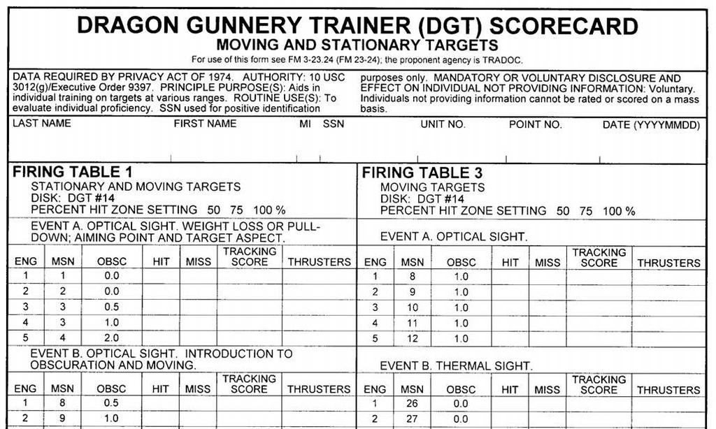
145
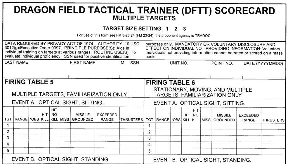
146
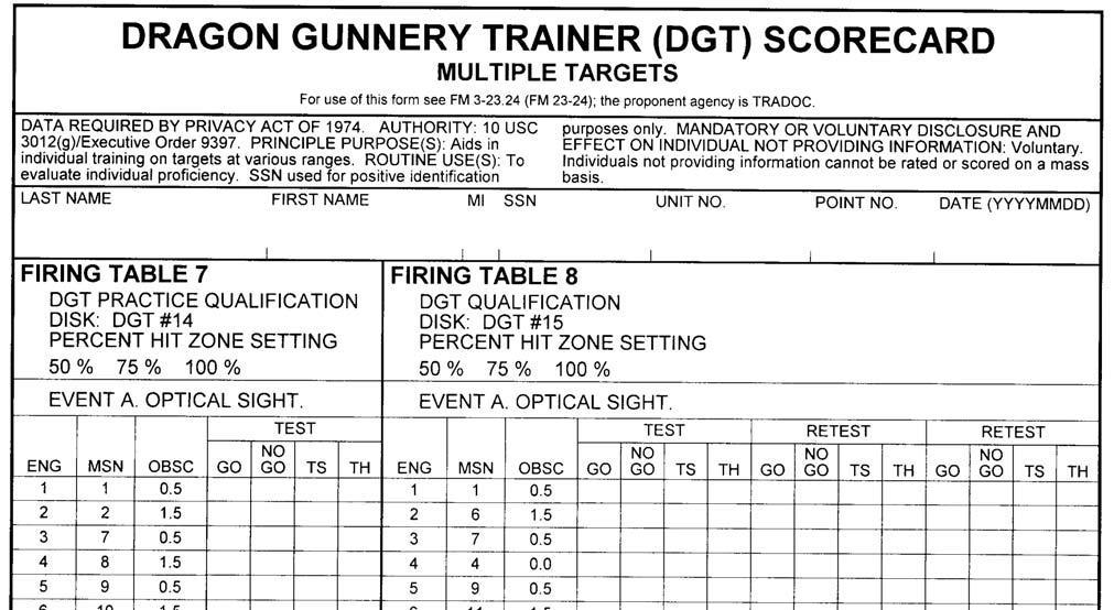
147
OPERATOR S MANUAL FOR MULTIPLE INTEGRATED LASER ENGAGEMENT SYSTEM (MILES) SIMULATOR SYSTEM, FIRING LASER: M83 (NSN ) FOR
 SIMULATOR SYSTEM, FIRING LASER: M83 (NSN ) FOR") Supersedes copy dated 18 October 1984 OPERATOR S MANUAL FOR MULTIPLE INTEGRATED LASER ENGAGEMENT SYSTEM (MILES) SIMULATOR SYSTEM, FIRING LASER: M83 (NSN 1265-01-158-4560) FOR M2/M3 FIGHTING VEHICLES DISTRIBUTION
Supersedes copy dated 18 October 1984 OPERATOR S MANUAL FOR MULTIPLE INTEGRATED LASER ENGAGEMENT SYSTEM (MILES) SIMULATOR SYSTEM, FIRING LASER: M83 (NSN 1265-01-158-4560) FOR M2/M3 FIGHTING VEHICLES DISTRIBUTION
40-MM GRENADE LAUNCHER, M203
 HEADQUARTERS FM 3-22.31 (FM 23-31) DEPARTMENT OF THE ARMY 40-MM GRENADE LAUNCHER, M203 FEBRUARY 2003 DISTRIBUTION RESTRICTION: Approved for public release; distribution is unlimited. *FM 3-22.31 (FM 23-31)
TECHNICAL MANUAL OPERATOR S MANUAL FOR MULTIPLE INTEGRATED LASER ENGAGEMENT SYSTEM (MILES) SIMULATOR SYSTEM, FIRING, LASER: M74 NSN
 SIMULATOR SYSTEM, FIRING, LASER: M74 NSN") TECHNICAL MANUAL OPERATOR S MANUAL MULTIPLE INTEGRATED LASER ENGAGEMENT SYSTEM (MILES) SIMULATOR SYSTEM, FIRING, LASER: M74 NSN 1265-01-159-0485 STINGER WEAPON SYSTEM HEADQUARTERS, DEPARTMENT OF THE ARMY
TECHNICAL MANUAL OPERATOR S MANUAL MULTIPLE INTEGRATED LASER ENGAGEMENT SYSTEM (MILES) SIMULATOR SYSTEM, FIRING, LASER: M74 NSN 1265-01-159-0485 STINGER WEAPON SYSTEM HEADQUARTERS, DEPARTMENT OF THE ARMY
* C1, FM BROWNING MACHINE GUN CALIBER.50 HB, M2 CONTENTS. PREFACE...iv
 * C1, FM 23-65 FIELD MANUAL No. 23-65 HEADQUARTERS DEPARTMENT OF THE ARMY Washington, DC, 19 June 1991 BROWNING MACHINE GUN CALIBER.50 HB, M2 CONTENTS PREFACE...iv * CHAPTER 1. INTRODUCTION 1-1. Training
Headquarters, Department of the Army
 FM 3-21.12 The Infantry Weapons Company July 2008 Distribution Restriction: Approved for public release; distribution is unlimited. Headquarters, Department of the Army This page intentionally left blank.
17895 Infantry Squad Battle Course (ISBC) RANGE DESIGN GUIDE
 RANGE DESIGN GUIDE") 17895 Infantry Squad Battle Course (ISBC) RANGE DESIGN GUIDE RANGE AND TRAINING LAND PROGRAM MANDATORY CENTER OF EXPERTISE U.S. ARMY ENGINEERING AND SUPPORT CENTER, HUNTSVILLE HUNTSVILLE, ALABAMA 256-895-1534
17895 Infantry Squad Battle Course (ISBC) RANGE DESIGN GUIDE RANGE AND TRAINING LAND PROGRAM MANDATORY CENTER OF EXPERTISE U.S. ARMY ENGINEERING AND SUPPORT CENTER, HUNTSVILLE HUNTSVILLE, ALABAMA 256-895-1534
HEADQUARTERS DEPARTMENT OF THE ARMY
 (FM 23-34) NOVEMBER 2003 HEADQUARTERS DEPARTMENT OF THE ARMY DISTRIBUTION RESTRICTION: Approved for public release; distribution is unlimited. *FM 3-22.34(FM 23-34) FIELD MANUAL NO. 3-22.34(23-34) HEADQUARTERS
THE STRYKER BRIGADE COMBAT TEAM INFANTRY BATTALION RECONNAISSANCE PLATOON
 FM 3-21.94 THE STRYKER BRIGADE COMBAT TEAM INFANTRY BATTALION RECONNAISSANCE PLATOON HEADQUARTERS DEPARTMENT OF THE ARMY DISTRIBUTION RESTRICTION: Approved for public release; distribution is unlimited.
TRAIN-THE-TRAINER PROGRAM
 CHAPTER 7 TRAIN-THE-TRAINER PROGRAM This manual and other training publications provide the trainers with the information they need for unit training. This chapter is an aid for the chain of command, who
OPERATOR S FOR MULTIPLE INTEGRATED LASER ENGAGEMENT SYSTEM (MILES) SIMULATOR SYSTEM, FIRING, LASER: M82 NSN FOR M1/M1A1 ABRAMS TANK
 SIMULATOR SYSTEM, FIRING, LASER: M82 NSN FOR M1/M1A1 ABRAMS TANK") Supersedes copy dated 15 December 1983 OPERATOR S MANUAL FOR MULTIPLE INTEGRATED LASER ENGAGEMENT SYSTEM (MILES) SIMULATOR SYSTEM, FIRING, LASER: M82 NSN 1265-01-137-7697 FOR M1/M1A1 ABRAMS TANK DISTRIBUTION
Supersedes copy dated 15 December 1983 OPERATOR S MANUAL FOR MULTIPLE INTEGRATED LASER ENGAGEMENT SYSTEM (MILES) SIMULATOR SYSTEM, FIRING, LASER: M82 NSN 1265-01-137-7697 FOR M1/M1A1 ABRAMS TANK DISTRIBUTION
MECHANIZED INFANTRY PLATOON AND SQUAD (BRADLEY)
") (FM 7-7J) MECHANIZED INFANTRY PLATOON AND SQUAD (BRADLEY) AUGUST 2002 HEADQUARTERS DEPARTMENT OF THE ARMY DISTRIBUTION RESTRICTION: Approved for public release; distribution is unlimited. *FM 3-21.71(FM
(FM 7-7J) MECHANIZED INFANTRY PLATOON AND SQUAD (BRADLEY) AUGUST 2002 HEADQUARTERS DEPARTMENT OF THE ARMY DISTRIBUTION RESTRICTION: Approved for public release; distribution is unlimited. *FM 3-21.71(FM
RECRUIT SUSTAINMENT PROGRAM SOLDIER TRAINING READINESS MODULES Conduct Squad Attack 17 June 2011
 RECRUIT SUSTAINMENT PROGRAM SOLDIER TRAINING READINESS MODULES Conduct Squad Attack 17 June 2011 SECTION I. Lesson Plan Series Task(s) Taught Academic Hours References Student Study Assignments Instructor
10 th INTERNATIONAL COMMAND AND CONTROL RESEARCH AND TECHNOLOGY SYMPOSIUM THE FUTURE OF C2
 10 th INTERNATIONAL COMMAND AND CONTROL RESEARCH AND TECHNOLOGY SYMPOSIUM THE FUTURE OF C2 Air Warfare Battlelab Initiative for Stabilized Portable Optical Target Tracking Receiver (SPOTTR) Topic Track:
TACTICAL EMPLOYMENT OF ANTIARMOR PLATOONS AND COMPANIES
 (FM 7-91) TACTICAL EMPLOYMENT OF ANTIARMOR PLATOONS AND COMPANIES HEADQUARTERS DEPARTMENT OF THE ARMY DECEMBER 2002 DISTRIBUTION RESTRICTION: Approved for public release; distribution is unlimited. (FM
THIS PAGE INTENTIONALLY LEFT BLANK
 THIS PAGE INTENTIONALLY LEFT BLANK DEPARTMENT OF THE ARMY OFFICE OF THE CHIEF OF ARMOR MCGINNIS-WICKAM HALL 1 KARKER STREET SUITE 6600 FORT BENNING, GEORGIA 31905-4500 ATZK-AR 14 February 2017 MEMORANDUM
TECHNICAL MANUAL UNIT AND DIRECT SUPPORT MAINTENANCE MANUAL (INCLUDING REPAIR PARTS AND SPECIAL TOOLS LIST) FOR LONG RANGE SNIPER RIFLE (LRSR), M107
 FOR LONG RANGE SNIPER RIFLE (LRSR), M107") TECHNICAL MANUAL UNIT AND DIRECT SUPPORT MAINTENANCE MANUAL (INCLUDING REPAIR PARTS AND SPECIAL TOOLS LIST) FOR LONG RANGE SNIPER RIFLE (LRSR), M107 (NSN 1005-01-469-2133) 6 DISTRIBUTION STATEMENT A Approved
TECHNICAL MANUAL UNIT AND DIRECT SUPPORT MAINTENANCE MANUAL (INCLUDING REPAIR PARTS AND SPECIAL TOOLS LIST) FOR LONG RANGE SNIPER RIFLE (LRSR), M107 (NSN 1005-01-469-2133) 6 DISTRIBUTION STATEMENT A Approved
TECHNICAL MANUAL OPERATOR S MANUAL FOR MULTIPLE INTEGRATED LASER ENGAGEMENT SYSTEM, (MILES) SIMULATOR SYSTEM, FIRING, LASER: M80
 SIMULATOR SYSTEM, FIRING, LASER: M80") This copy is a reprint which includes current pages from Change 1. TECHNICAL MANUAL OPERATOR S MANUAL MULTIPLE INTEGRATED LASER ENGAGEMENT SYSTEM, (MILES) SIMULATOR SYSTEM, FIRING, LASER: M80 AH-1S ATTACK
This copy is a reprint which includes current pages from Change 1. TECHNICAL MANUAL OPERATOR S MANUAL MULTIPLE INTEGRATED LASER ENGAGEMENT SYSTEM, (MILES) SIMULATOR SYSTEM, FIRING, LASER: M80 AH-1S ATTACK
Tactical Employment of Mortars
 MCWP 3-15.2 FM 7-90 Tactical Employment of Mortars U.S. Marine Corps PCN 143 000092 00 *FM 7-90 Field Manual NO. 7-90 FM 7-90 MCWP 3-15.2 TACTICAL EMPLOYMENT OF MORTARS HEADQUARTERS DEPARTMENT OF THE
INTRODUCTION TO CREW SERVED WEAPONS B3M4078 STUDENT HANDOUT
 UNITED STATES MARINE CORPS THE BASIC SCHOOL MARINE CORPS TRAINING COMMAND CAMP BARRETT, VIRGINIA 22134-5019 INTRODUCTION TO CREW SERVED WEAPONS B3M4078 STUDENT HANDOUT Basic Officer Course Introduction
CHAPTER 5 SECURITY OPERATIONS
 CHAPTER 5 SECURITY OPERATIONS The reconnaissance platoon conducts security operations to protect the main body from enemy observation and surprise attack. These operations give the main body commander
NATURE OF THE ASSAULT
 Chapter 5 Assault Breach The assault breach allows a force to penetrate an enemy s protective obstacles and destroy the defender in detail. It provides a force with the mobility it needs to gain a foothold
HQ AFOATS AIR FORCE JUNIOR RESERVE OFFICER TRAINING CORPS (AFJROTC)
") HQ AFOATS AIR FORCE JUNIOR RESERVE OFFICER TRAINING CORPS (AFJROTC) (Prepared 2002) J R O T C INTERSERVICE CROSS-INDEX DRILL MANUAL TABLE OF CONTENTS FOREWORD..............................................
HQ AFOATS AIR FORCE JUNIOR RESERVE OFFICER TRAINING CORPS (AFJROTC) (Prepared 2002) J R O T C INTERSERVICE CROSS-INDEX DRILL MANUAL TABLE OF CONTENTS FOREWORD..............................................
Chapter 3. Types of Training. The best form of welfare for the troops is first class training, for this saves unnecessary casualties.
 Chapter 3 Types of Training The best form of welfare for the troops is first class training, for this saves unnecessary casualties. 3 Field Marshal Erwin Rommel The Marine Corps UTM program addresses both
dust warfare: glossary
 In war-time, truth is so precious that she should always be attended by a bodyguard of lies. Winston Churchill This is the Dust Warfare glossary. This collection of terms serves as a quick reference guide
(QJLQHHU 5HFRQQDLVVDQFH FM Headquarters, Department of the Army
 FM 5-170 (QJLQHHU 5HFRQQDLVVDQFH Headquarters, Department of the Army DISTRIBUTION RESTRICTION: Approved for public release; distribution is unlimited. *FM 5-170 Field Manual No. 5-170 Headquarters Department
Low Altitude Air Defense (LAAD) Gunner's Handbook
 Gunner's Handbook") MCRP 3-25.10A Low Altitude Air Defense (LAAD) Gunner's Handbook U.S. Marine Corps PCN 144 000092 00 To Our Readers Changes: Readers of this publication are encouraged to submit suggestions and changes
MCRP 3-25.10A Low Altitude Air Defense (LAAD) Gunner's Handbook U.S. Marine Corps PCN 144 000092 00 To Our Readers Changes: Readers of this publication are encouraged to submit suggestions and changes
TECHNICAL MANUAL OPERATOR AND UNIT MAINTENANCE MANUAL INCLUDING REPAIR PARTS AND SPECIAL TOOLS LIST
 *TM 10-1670-262-12&P TECHNICAL MANUAL OPERATOR AND UNIT MAINTENANCE MANUAL INCLUDING REPAIR PARTS AND SPECIAL TOOLS LIST PERSONNEL INSERTION/EXTRACTION SYSTEMS FOR STABO (NSN 1670-00-168-5952, NSN 1670-00-168-6064,
BY ORDER OF THE AIR FORCE MANUAL , VOLUME 3 SECRETARY OF THE AIR FORCE 1 MARCH 1996
 BY ORDER OF THE AIR FORCE MANUAL 36-2227, VOLUME 3 SECRETARY OF THE AIR FORCE 1 MARCH 1996 Personnel COMBAT ARMS TRAINING AND MAINTENANCE M60 MACHINE GUN, MK 19 40MM MACHINE GUN, AND M2.50 CALIBER MACHINE
This publication is available digitally on the AFDPO WWW site at:
 BY ORDER OF THE SECRETARY OF THE AIR FORCE AIR FORCE MANUAL 36-2227, VOLUME 2 1 JANUARY 2004 Personnel COMBAT ARMS TRAINING PROGRAMS CREW SERVED WEAPONS COMPLIANCE WITH THIS PUBLICATION IS MANDATORY NOTICE:
Standards in Weapons Training
 Department of the Army Pamphlet 350 38 Training Standards in Weapons Training UNCLASSIFIED Headquarters Department of the Army Washington, DC 22 November 2016 SUMMARY of CHANGE DA PAM 350 38 Standards
Appendix H. MOUT Under Limited-Visibility Conditions
 Appendix H MOUT Under Limited-Visibility Conditions To be successful, leaders must use limited-visibility conditions to their advantage. 1. Advantages. When fighting in built-up areas during night or periods
TACTICAL ROAD MARCHES AND ASSEMBLY AREAS
 APPENDIX Q TACTICAL ROAD MARCHES AND ASSEMBLY AREAS Section I. TACTICAL ROAD MARCHES Q-1. GENERAL The ground movement of troops can be accomplished by administrative marches, tactical movements, and tactical
17897 Infantry Platoon Battle Course (IPBC) RANGE DESIGN GUIDE
 RANGE DESIGN GUIDE") 17897 Infantry Platoon Battle Course (IPBC) RANGE DESIGN GUIDE RANGE AND TRAINING LAND PROGRAM MANDATORY CENTER OF EXPERTISE U.S. ARMY ENGINEERING AND SUPPORT CENTER, HUNTSVILLE HUNTSVILLE, ALABAMA 256-895-1534
17897 Infantry Platoon Battle Course (IPBC) RANGE DESIGN GUIDE RANGE AND TRAINING LAND PROGRAM MANDATORY CENTER OF EXPERTISE U.S. ARMY ENGINEERING AND SUPPORT CENTER, HUNTSVILLE HUNTSVILLE, ALABAMA 256-895-1534
INFANTRY LIVE-FIRE TRAINING
 INFANTRY LIVE-FIRE TRAINING HEADQUARTERS, DEPARTMENT OF THE ARMY DISTRIBUTION RESTRICTION: Approved for public release; distribution is unlimited. This publication is available at Army Knowledge Online
CD Compilation Copyright by emilitary Manuals
 Field Manual No. 25-4 FM 25-4 HEADQUARTERS DEPARTMENT OF THE ARMY Washington, DC, 10 September 1984 HOW TO CONDUCT TRAINING EXERCISES Table of Contents * This publication supersedes FM 105-5, 31 December
Perform remedial action for a squad automatic weapon (B)
") ADMINISTRATIVE INSTRUCTIONS: This task should be trained to standard through the use of the Individual Small-Arms Marksmanship Trainer (ISMT) prior to the expenditure of live rounds. If this equipment
ADMINISTRATIVE INSTRUCTIONS: This task should be trained to standard through the use of the Individual Small-Arms Marksmanship Trainer (ISMT) prior to the expenditure of live rounds. If this equipment
OPERATOR, UNIT, AND DIRECT SUPPORT MAINTENANCE MANUAL INCLUDING REPAIR PARTS AND SPECIAL TOOLS LIST for TELESCOPE, STRAIGHT: M145 ( )
") OPERATOR, UNIT, AND DIRECT SUPPORT MAINTENANCE MANUAL INCLUDING REPAIR PARTS AND SPECIAL TOOLS LIST for TELESCOPE, STRAIGHT: M145 (1240-01-411-6350) Distribution Statement A Approved for public release;
OPERATOR, UNIT, AND DIRECT SUPPORT MAINTENANCE MANUAL INCLUDING REPAIR PARTS AND SPECIAL TOOLS LIST for TELESCOPE, STRAIGHT: M145 (1240-01-411-6350) Distribution Statement A Approved for public release;
CHAPTER 8. Range Training Facilities. Section I. LIVE-FIRE RANGES
 CHAPTER 8 Range Training Facilities The light cavalry training program includes range firing and using training areas for dry-fire tables. This program builds on gunnery skills and tactical training gained
INTRODUCTION TO CREW SERVED WEAPONS W3I0001XQ-DM STUDENT HANDOUT
 UNITED STATES MARINECORPS THE BASIC SCHOOL MARINE CORPS TRAINING COMMAND CAMP BARRETT, VIRGINIA 22134-5019 INTRODUCTION TO CREW SERVED WEAPONS W3I0001XQ-DM STUDENT HANDOUT Warrant Officer Basic Course
CODE OF MARYLAND REGULATIONS (COMAR) As Amended through November 25, 2013
 As Amended through November 25, 2013") CODE OF MARYLAND REGULATIONS (COMAR) As Amended through November 25, 2013 Title 12 DEPARTMENT OF PUBLIC SAFETY AND CORRECTIONAL SERVICES Subtitle 04 POLICE TRAINING COMMISSION Chapter 02 Firearms Training
CODE OF MARYLAND REGULATIONS (COMAR) As Amended through November 25, 2013 Title 12 DEPARTMENT OF PUBLIC SAFETY AND CORRECTIONAL SERVICES Subtitle 04 POLICE TRAINING COMMISSION Chapter 02 Firearms Training
By Lieutenant Colonel Scott Jones and Major Detrick L. Briscoe
 By Lieutenant Colonel Scott Jones and Major Detrick L. Briscoe The 94th Military Police Battalion in Yongsan, Korea, continues to prepare soldiers and leaders to fight tonight by conducting tough, realistic,
18. WARHEADS AND GUIDANCE SYSTEMS
 Briefing 1. A wide range of weapons is capable of firing projectiles with warheads. Many of these weapons can fire more than one type of warhead. Most warheads combine a powerful attack factor with an
Why Should You Consider Simulators?
 Why Should You Consider Simulators? Individual Marksmanship Units still have soldiers with issues in grouping, zeroing and qualifying with individual weapons Identify soldiers requiring remedial training
Appendix E. Subterranean Operations
 Appendix E Subterranean Operations Knowledge of the nature and location of underground facilities is valuable to both the urban attacker and defender. 1. Tactical Value. Fighting in MOUT is multidimensional.
CHAPTER 3 ENVIRONMENTAL EFFECTS ON OPERATIONS
 CHAPTER 3 ENVIRONMENTAL EFFECTS ON OPERATIONS Weather information is critical to aviation planning. Aviation commanders and staffs must have current weather forecasts and observations throughout the entire
CHAPTER 10. PATROL PREPARATION
 CHAPTER 10. PATROL PREPARATION For a patrol to succeed, all members must be well trained, briefed, and rehearsed. The patrol leader must have a complete understanding of the mission and a thorough understanding
CODE OF MARYLAND REGULAITONS (COMAR)
") CODE OF MARYLAND REGULAITONS (COMAR) Title 12 DEPARTMENT OF PUBLIC SAFETY AND CORRECTIONAL SERVICES Subtitle 04 POLICE TRAINING COMMISSION Chapter 02 Firearms Training and Instructor Certification Authority:
CODE OF MARYLAND REGULAITONS (COMAR) Title 12 DEPARTMENT OF PUBLIC SAFETY AND CORRECTIONAL SERVICES Subtitle 04 POLICE TRAINING COMMISSION Chapter 02 Firearms Training and Instructor Certification Authority:
Stryker Brigade Combat Team, Antiarmor Company, and Platoon Leaders' Handbook
 ST 3-22.6 Special Text No. 3-22.6 US Army Infantry School Fort Benning, GA 8 June 2009 Stryker Brigade Combat Team, Antiarmor Company, and Platoon Leaders' Handbook Contents PREFACE... vii Chapter 1 SBCT
Ammunition and Explosives related Federal Supply Classes (FSC)
") GROUP 13 Ammunition and Explosives Note-Excluded from this group are items specially designed for nuclear ordnance application. 1305 Ammunition, through 30mm Includes Components. 1310 Ammunition, over
GROUP 13 Ammunition and Explosives Note-Excluded from this group are items specially designed for nuclear ordnance application. 1305 Ammunition, through 30mm Includes Components. 1310 Ammunition, over
IDENTIFY THE TROOP LEADING PROCEDURE
 Lesson 1 IDENTIFY THE TROOP LEADING PROCEDURE Lesson Description: OVERVIEW In this lesson you will learn to identify the troop leading procedure (TLP) and its relationship with the estimate of the situation.
Summary Report for Individual Task Issue Fire Orders for Direct Fire Mission Status: Approved
 Report Date: 05 Jun 2013 Summary Report for Individual Task 061-266-3320 Issue Fire Orders for Direct Fire Mission Status: Approved DISTRIBUTION RESTRICTION: Approved for public release; distribution is
New Artillery Sunday Punch
 Pershing... New Artillery Sunday Punch Lt Col William T. Hatter Guided Missile Department Solid propellants, automatic checkout, and new concepts in ground handling equipment and procedures have resulted
Infantry Battalion Operations
 .3 Section II Infantry Battalion Operations MCWP 3-35 2201. Overview. This section addresses some of the operations that a task-organized and/or reinforced infantry battalion could conduct in MOUT. These
DEPARTMENT OF THE ARMY SUPPLY BULLETIN
 SB 742-1370-94-704 DEPARTMENT OF THE ARMY SUPPLY BULLETIN SIGNAL, ILLUMINATION, AIRCRAFT, SINGLE STAR: RED-AN-M43A1/A2 (1370-L231) YELLOW-AN-M44A1/A2 (1370-L232) GREEN-AN-M45A1/A2 (1370-L233) AMMUNITION
Section III. Delay Against Mechanized Forces
 Section III. Delay Against Mechanized Forces A delaying operation is an operation in which a force under pressure trades space for time by slowing down the enemy's momentum and inflicting maximum damage
DEPARTMENT OF THE ARMY TECHNICAL MANUAL OPERATOR S MANUAL FOR
 TM 9 2350 311 10 Supersedes TM 9 2350 311 10 and LO 9 2350 311 12, dated June 1986, and all changes DESCRIPTION AND USE OF OPERATOR S CONTROLS AND INDICATORS 2 2 DEPARTMENT OF THE ARMY TECHNICAL MANUAL
MORTAR TRAINING STRATEGY
 APPENDIX A MORTAR TRAINING STRATEGY This appendix provides a comprehensive unit training strategy for training mortarmen. Leaders have the means to develop a program for training their mortar units to
ARTEP 7-8-DRILL JUNE DISTRIBUTION RESTRICTION--Approved for public release; distribution is unlimited.
 JUNE 2002 DISTRIBUTION RESTRICTION--Approved for public release; distribution is unlimited. ARMY TRAINING AND HEADQUARTERS EVALUATION PROGRAM DEPARTMENT OF THE ARMY No. 7-8-DRILL Washington, DC, 25 June
JAVELIN ANTITANK MISSILE
 JAVELIN ANTITANK MISSILE Army ACAT ID Program Total Number of Systems: Total Program Cost (TY$): Average CLU Cost (TY$): Average Missile Cost (TY$): Full-rate production: 4,348 CLUs 28,453 missiles $3618M
ROUTE CLEARANCE FM APPENDIX F
 APPENDIX F ROUTE CLEARANCE The purpose of this appendix is to assist field units in route-clearance operations. The TTP that follow establish basic guidelines for conducting this combined-arms combat operation.
CARRIER, PERSONNEL, FULL TRACKED, ARMORED, M113A CARRIER, COMMAND POST, LIGHT TRACKED, M577A
 OPERATOR S MANUAL CARRIER, PERSONNEL, FULL TRACKED, ARMORED, M113A2 2350-01-068-4077 CARRIER, COMMAND POST, LIGHT TRACKED, M577A2 2350-01-068-4089 CARRIER, MORTAR, 107-MM, M30; SELF-PROPELLED, M106A2 2350-01-069-6931
Soldier Division Director David Libersat June 2, 2015
 Soldier Division Director David Libersat June 2, 2015 Soldier Division Maneuver Center of Excellence Soldier Division develops future requirements and manages Soldier capabilities for all Soldiers across
UNITED STATES MARINE CORPS Echo Company 2nd Battalion, 5th Marines Camp Pendleton, California 92055
 UNITED STATES MARINE CORPS Echo Company 2nd Battalion, 5th Marines Camp Pendleton, California 92055 20 Mar 00 From: Execution Officer To: Echo Distribution Subj: FIELD TRAINING PLAN FOR ISMT PLATOON WEAPONS
AIRCRAFT WEAPONS SYSTEMS TEST EQUIPMENT
 CHAPTER 16 AIRCRAFT WEAPONS SYSTEMS TEST EQUIPMENT Aviation ordnancemen use test equipment in all phases of electrical testing of weapons systems. The testing procedures you use are required at specific
TECHNICAL MANUAL OPERATOR, UNIT, AND DIRECT SUPPORT MAINTENANCE MANUAL (INCLUDING REPAIR PARTS AND SPECIAL TOOLS LIST)
") TECHNICAL MANUAL OPERATOR, UNIT, AND DIRECT SUPPORT MAINTENANCE MANUAL (INCLUDING REPAIR PARTS AND SPECIAL TOOLS LIST) TANK, FABRIC, COLLAPSIBLE, WATER, 3,000 AND 5,000 GALLONS, SEMI-TRAILER MOUNTED 3,000
TECHNICAL MANUAL OPERATOR, UNIT, AND DIRECT SUPPORT MAINTENANCE MANUAL (INCLUDING REPAIR PARTS AND SPECIAL TOOLS LIST) TANK, FABRIC, COLLAPSIBLE, WATER, 3,000 AND 5,000 GALLONS, SEMI-TRAILER MOUNTED 3,000
TANK GUNNERY TRAINING DEVICES AND USAGE STRATEGIES
 Field Manual *FM 17-12-7 No. 17-12-7 Headquarters Department of the Army Washington, DC, 1 May 2000 TANK GUNNERY TRAINING DEVICES AND USAGE STRATEGIES Table of Contents Page Preface... iii Chapter 1. Introduction...
OPERATOR S MANUAL MULTIPLE INTEGRATED LASER ENGAGEMENT SYSTEM (MILES) SIMULATOR SYSTEM, FIRING, LASER: M89 (NSN ) FOR
 SIMULATOR SYSTEM, FIRING, LASER: M89 (NSN ) FOR") OPERATOR S MANUAL MULTIPLE INTEGRATED LASER ENGAGEMENT SYSTEM (MILES) SIMULATOR SYSTEM, FIRING, LASER: M89 (NSN 1265-01-236-6725) M16A1/M16A2 RIFLE AND SIMULATOR SYSTEM, FIRING, LASER: M90 (NSN 1265-01-236-6724)
OPERATOR S MANUAL MULTIPLE INTEGRATED LASER ENGAGEMENT SYSTEM (MILES) SIMULATOR SYSTEM, FIRING, LASER: M89 (NSN 1265-01-236-6725) M16A1/M16A2 RIFLE AND SIMULATOR SYSTEM, FIRING, LASER: M90 (NSN 1265-01-236-6724)
TECHNICAL MANUAL OPERATOR S MANUAL FOR MULTIPLE INTEGRATED LASER ENGAGEMENT SYSTEM (MILES) INDICATOR, SIMULATOR SYSTEM,
 INDICATOR, SIMULATOR SYSTEM,") TECHNICAL MANUAL OPERATOR S MANUAL FOR MULTIPLE INTEGRATED LASER ENGAGEMENT SYSTEM (MILES) INDICATOR, SIMULATOR SYSTEM, LASER TARGET INTERFACE DEVICE (LTID) (NSN 1265-01-221-9438) Distribution Statement
TECHNICAL MANUAL OPERATOR S MANUAL FOR MULTIPLE INTEGRATED LASER ENGAGEMENT SYSTEM (MILES) INDICATOR, SIMULATOR SYSTEM, LASER TARGET INTERFACE DEVICE (LTID) (NSN 1265-01-221-9438) Distribution Statement
CHAPTER 2 DUTIES OF THE FIRE SUPPORT TEAM AND THE OBSERVER
 CHAPTER 2 DUTIES OF THE FIRE SUPPORT TEAM AND THE OBSERVER 2-1. FIRE SUPPORT TEAM a. Personnel and Equipment. Indirect fire support is critical to the success of all maneuver operations. To ensure the
Summary Report for Individual Task A-0048 Borescope the 120 MM Main Gun on the M1A1/M1A2 Series Track Vehicle Status: Approved
 Summary Report for Individual Task 091-91A-0048 Borescope the 120 MM Main Gun on the M1A1/M1A2 Series Track Vehicle Status: Approved Report Date: 28 May 2014 Distribution Restriction: Approved for public
Distribution Statement A: Approved for public release; distribution is unlimited.
 TECHNICAL MANUAL OPERATOR'S, UNIT, DIRECT SUPPORT AND GENERAL SUPPORT MAINTENANCE MANUAL OPERATING INSTRUCTIONS 2-1 OPERATOR PREVENTIVE 2-5 MAINTENANCE CHECKS AND SERVICES (PMCS) OPERATOR 3-1 TROUBLESHOOTING
COMBINED ARMS OPERATIONS IN URBAN TERRAIN
 (FM 90-10-1) COMBINED ARMS OPERATIONS IN URBAN TERRAIN HEADQUARTERS DEPARTMENT OF THE ARMY DISTRIBUTION RESTRICTION: Approved for public release; distribution is unlimited. *FM 3-06.11 (FM 90-10-1) FIELD
Summary Report for Individual Task Supervise a CBRN Reconnaissance Status: Approved
 Report Date: 13 Mar 2014 Summary Report for Individual Task 031-516-2039 Supervise a CBRN Reconnaissance Status: Approved DISTRIBUTION RESTRICTION: Approved for public release; distribution is unlimited.
M16A1 AND M16A2 RIFLE
 TM 9-1265-370-10-1 Supersedes copy dated 22 January 1982 OPERATOR S MANUAL MULTIPLE INTEGRATED LASER ENGAGEMENT SYSTEM (MILES) SIMULATOR SYSTEM, FIRING LASER: M60 (NSN 1265-01-085-1583) FOR M16A1 AND M16A2
HEADQUARTERS DEPARTMENT OF THE ARMY FM US ARMY AIR AND MISSILE DEFENSE OPERATIONS
 HEADQUARTERS DEPARTMENT OF THE ARMY FM 44-100 US ARMY AIR AND MISSILE DEFENSE OPERATIONS Distribution Restriction: Approved for public release; distribution is unlimited FM 44-100 Field Manual No. 44-100
ARMY TM &P MARINE CORPS TM 10291A-12&P
 ARMY TM 9-1240-407-12&P MARINE CORPS TM 10291A-12&P OPERATOR S AND UNIT MAINTENANCE MANUAL (INCLUDING REPAIR PARTS LIST) BINOCULAR, M24 (NSN 1240-01-412-3128) w/reticle (NSN 1240-01-430-6944) DISTRIBUTION
TECHNICAL MANUAL OPERATOR'S, UNIT, DIRECT SUPPORT, AND GENERAL SUPPORT MAINTENANCE MANUAL
 TECHNICAL MANUAL OPERATOR'S, UNIT, DIRECT SUPPORT, AND GENERAL SUPPORT MAINTENANCE MANUAL AIR CONDITIONER, HORIZONTAL, COMPACT, 36,000 BTU/HR, MULTI-POWER INPUT 208V, 3 PHASE, 50/60/400 HZ MODEL MH-40-MP
EMPLOYMENT OF THE DRAGON
 CHAPTER 3 EMPLOYMENT OF THE DRAGON This chapter discusses considerations for and techniques of employment for the Dragon during offensive, defensive, and retrograde operations. This chapter is keyed to
OPERATOR, ORGANIZATIONAL, DIRECT SUPPORT AND GENERAL SUPPORT MAINTENANCE MANUAL (INCLUDING REPAIR PARTS AND SPECIAL TOOLS LIST AND
 *TM 9-1270-212-14&P TECHNICAL MANUAL No. 9-1270-212-14&P HEADQUARTERS DEPARTMENT OF THE ARMY WASHINGTON, D. C., 10 JULY 1981 OPERATOR, ORGANIZATIONAL, DIRECT SUPPORT AND GENERAL SUPPORT MAINTENANCE MANUAL
STANDING OPERATING PROCEDURE (SOP) RANGE OPERATIONS HAND GRENADE RANGE IMSM-PLR 1 OCT 2016 TABLE OF CONTENTS
 RANGE OPERATIONS HAND GRENADE RANGE IMSM-PLR 1 OCT 2016 TABLE OF CONTENTS") STANDING OPERATING PROCEDURE (SOP) RANGE OPERATIONS HAND GRENADE RANGE IMSM-PLR 1 OCT 2016 TABLE OF CONTENTS 1. References. 2 2. Purpose.. 2 3. Organization.. 2 4. Scope. 2 5. Certification.. 2 6. Descriptions..
STANDING OPERATING PROCEDURE (SOP) RANGE OPERATIONS HAND GRENADE RANGE IMSM-PLR 1 OCT 2016 TABLE OF CONTENTS 1. References. 2 2. Purpose.. 2 3. Organization.. 2 4. Scope. 2 5. Certification.. 2 6. Descriptions..
Air Defense System Solutions.
 Air Defense System Solutions www.aselsan.com.tr ADSS AIR DEFENSE SYSTEM SOLUTIONS AIR DEFENSE SYSTEM SOLUTIONS Effective air defense is based on integration and coordinated use of airborne and/or ground
Training and Evaluation Outline Report
 Training and Evaluation Outline Report Status: Approved 20 Mar 2015 Effective Date: 15 Sep 2016 Task Number: 71-8-5715 Task Title: Control Tactical Airspace (Brigade - Corps) Distribution Restriction:
Figure Company Attack of a Block
 Section III Rifle Company Operations 2301. Overview. This section addresses some of the operations the infantry battalion could assign to the rifle company in MOUT. For our focus, the rifle company is
The Infantry Rifle Platoon and Squad
 FM 3-21.8 (FM 7-8) The Infantry Rifle Platoon and Squad MARCH 2007 DISTRIBUTION RESTRICTION: Approved for public release; distribution is unlimited. HEADQUARTERS DEPARTMENT OF THE ARMY This page intentionally
Summary Report for Individual Task H-1532 Operate 5K Light Capacity Rough Terrain Forklift (LCRTF) Without a Load Status: Approved
 Without a Load Status: Approved") Summary Report for Individual Task 551-88H-1532 Operate 5K Light Capacity Rough Terrain Forklift (LCRTF) Without a Load Status: Approved Report Date: 21 May 2014 Distribution Restriction: Approved for
Summary Report for Individual Task 551-88H-1532 Operate 5K Light Capacity Rough Terrain Forklift (LCRTF) Without a Load Status: Approved Report Date: 21 May 2014 Distribution Restriction: Approved for
Tactics, Techniques, and Procedures for the Field Artillery Cannon Battery
 FM 6-50 MCWP 3-16.3 Tactics, Techniques, and Procedures for the Field Artillery Cannon Battery U.S. Marine Corps PCN 143 000004 00 FOREWORD This publication may be used by the US Army and US Marine Corps
150-MC-0006 Validate the Protection Warfighting Function Staff (Battalion through Corps) Status: Approved
 Status: Approved") Report Date: 14 Jun 2017 150-MC-0006 Validate the Protection Warfighting Function Staff (Battalion through Corps) Status: Approved Distribution Restriction: Approved for public release; distribution is
Report Date: 14 Jun 2017 150-MC-0006 Validate the Protection Warfighting Function Staff (Battalion through Corps) Status: Approved Distribution Restriction: Approved for public release; distribution is
CHAPTER COUNTERMINE OPERATIONS DEFINITIONS BREACHING OPERATIONS. Mine/Countermine Operations FM 20-32
 Mine/Countermine Operations FM 20-32 CHAPTER 8 COUNTERMINE OPERATIONS Countermine operations are taken to breach or clear a minefield. All tasks fall under breaching or clearing operations. These tasks
History of Fire Control and the Application of Implementing Technologies Victor Galgano & Ralph Tillinghast May 2012
 U.S. Army Research, Development and Engineering Command History of Fire Control and the Application of Implementing Technologies Victor Galgano & Ralph Tillinghast May 2012 DISTRIBUTION STATEMENT A: Approved
Summary Report for Individual Task N-1125 Operate Force XXI Battle Command Brigade and Below (FBCB2) for Movement Operations Status: Approved
 for Movement Operations Status: Approved") Report Date: 24 Jun 2014 Summary Report for Individual Task 551-88N-1125 Operate Force XXI Battle Command Brigade and Below (FBCB2) for Movement Operations Status: Approved Distribution Restriction: Approved
Report Date: 24 Jun 2014 Summary Report for Individual Task 551-88N-1125 Operate Force XXI Battle Command Brigade and Below (FBCB2) for Movement Operations Status: Approved Distribution Restriction: Approved
DRILLS FOR THE SMOKE/DECONTAMINATION PLATOON
 HEADQUARTERS, DEPARTMENT OF THE ARMY ARTEP 3-457-10-DRILL DRILLS FOR THE SMOKE/DECONTAMINATION PLATOON DISTRIBUTION RESTRICTION: Approved for public release; distribution is unlimited. i ARTEP 19-100-10-DRILL
DISTRIBUTION RESTRICTION:
 FM 3-21.31 FEBRUARY 2003 HEADQUARTERS DEPARTMENT OF THE ARMY DISTRIBUTION RESTRICTION: Approved for public release; distribution is unlimited. FIELD MANUAL NO. 3-21.31 HEADQUARTERS DEPARTMENT OF THE ARMY
Chapter 1. Introduction
 MCWP -. (CD) 0 0 0 0 Chapter Introduction The Marine-Air Ground Task Force (MAGTF) is the Marine Corps principle organization for the conduct of all missions across the range of military operations. MAGTFs
Exhibit R-2, RDT&E Budget Item Justification
 PE NUMBER: 0603500F PE TITLE: MULTI-DISCIPLINARY ADV Exhibit R-2, RDT&E Budget Item Justification BUDGET ACTIVITY PE NUMBER AND TITLE Cost ($ in Millions) FY 2006 FY 2007 FY 2008 FY 2009 FY 2010 FY 2011
TECHNICAL MANUAL UNIT AND INTERMEDIATE DIRECT SUPPORT (DS) MAINTENANCE MANUAL (INCLUDING REPAIR PARTS AND SPECIAL TOOLS LIST) FOR
 MAINTENANCE MANUAL (INCLUDING REPAIR PARTS AND SPECIAL TOOLS LIST) FOR") AIR FORCE TO 13C5-26-2 MARINE CORPS TM 01109C-23&P/1 TECHNICAL MANUAL UNIT AND INTERMEDIATE DIRECT SUPPORT (DS) MAINTENANCE MANUAL (INCLUDING REPAIR PARTS AND SPECIAL TOOLS LIST) FOR PARACHUTE, CARGO TYPE:
AIR FORCE TO 13C5-26-2 MARINE CORPS TM 01109C-23&P/1 TECHNICAL MANUAL UNIT AND INTERMEDIATE DIRECT SUPPORT (DS) MAINTENANCE MANUAL (INCLUDING REPAIR PARTS AND SPECIAL TOOLS LIST) FOR PARACHUTE, CARGO TYPE:
SOLDIER'S MANUAL/TRAINER'S GUIDE QUARTERMASTER AND CHEMICAL EQUIPMENT REPAIRER SKILL LEVELS 1, 2 MOS 63J
 SOLDIER'S MANUAL/TRAINER'S GUIDE QUARTERMASTER AND CHEMICAL EQUIPMENT REPAIRER SKILL LEVELS 1, 2 MOS 63J DISTRIBUTION RESTRICTION: Approved for public release; distribution is unlimited. DESTRUCTION NOTICE:
Preparing to Occupy. Brigade Support Area. and Defend the. By Capt. Shayne D. Heap and Lt. Col. Brent Coryell
 Preparing to Occupy and Defend the Brigade Support Area By Capt. Shayne D. Heap and Lt. Col. Brent Coryell A Soldier from 123rd Brigade Support Battalion, 3rd Brigade Combat Team, 1st Armored Division,
Ceremonial Bugle Operation Manual and Military Funeral Honors Guide
 S & D Consulting Int, Ltd. Ceremonial Bugle Operation Manual and Military Funeral Honors Guide Limited Warranty S & D Consulting Int, Ltd. guarantees the insert to be materially free from defects and to
The distance between the battery centre and a target. An instrument used to determine the distance between an observer and the target.
 R Rammer Range Range Finder Range Tables Ranging Rapier Control System Rapier Fire Units Rate of Fire Ready Reciprocating Sight Recoil Recoil System Record as Target A tool used by gunners to ram home,
The non-rifled, tapered portion at the inside-rear of the of the barrel that receives the cartridge/charge.
 C Calculation of Firing Data Calibration Calibre Call for Fire Cancel At My Command Captain-General The battery command post (BCP) calculates the map bearing, range and angle of sight between the gun and