Major Qualifying Project
|
|
|
- Elwin Reynold Robbins
- 5 years ago
- Views:
Transcription

1 The Design and Prototyping of a Medical Lifting Device Major Qualifying Project A Major Qualifying Project Report submitted by the Faculty of WORCESTER POLYTECHNIC INSTITUTE In fulfillment of the requirements for the Degree of Bachelor of Science Submitted to: Project Advisor: John M. Sullivan Submitted by: Alvaro E. Galindo Aaron M. Hartford Jasmine Higuera C. Colin C. Mashack Date Submitted: 23 March 2018
2 Abstract The goal of this project was to design and prototype an affordable, mobile and more compact medical lifting device that can safely lift an immobile patient from a bed to a wheelchair or restroom without requiring an external electrical power source. This project also aims to decrease the number of back injuries reported by nursing assistants, completing the lifting process mechanically opposed to manually. Throughout the early stages of this project, reiterations of the model were executed resulting in the desired outcome for the final design. Following, the final design was manufactured into a prototype made of Aluminum 6061 to decrease costs of fabrication. Load testing was completed to simulate when the device lifts a patient to determine weak points in the design. In conclusion, the Medical Lifting prototype can lift up to 275 lbs., which is a lower weight than expected. Additionally, the overall price of this device is approximately $1,000 and when stored, fits inside a 33 in. X 25 in. X 60 in. cube. Finally, to increase the strength and safety of this device, the team made recommendations to redesign a more durable model in the future. i
3 Acknowledgements The merit and completion of this Major Qualifying Project was possible thanks to our advisor, Professor John Sullivan, for providing guidance for this project. We would like to thank Professor Makhlouf Makhlouf for giving us the technical guidance in material selection for the aluminum distinct mechanical properties and how they are influenced by its chemical properties and thermal treatments. We would like to thank Professor Diana Lados for clearing up any concerns we had about the CES EduPack We would like to thanks both Professor Holly Ault and Professor Pradeep Radhakrishnan for verifying our stress. Thank you WP Writing Center staff for your recommendations and feedback on our paper. We would like to thank Ian Anderson for teaching us the safety steps for welding and teaching us how to weld in Washburn. We would like to thank Tom for giving us advice for milling some of our parts in the Higgins Labs. We would like to thank Barbara Furhman for helping us with purchasing the parts to complete this project. Nevertheless, a special gratitude to the facilities of Worcester Polytechnic Institute who granted us the necessary equipment and lab monitors to safely manufacture our prototype. ii
4 Table of Contents Abstract... i Acknowledgements... ii List of Figures... v List of Tables... vii 1 Introduction Background Lifting Processes Manual Lifting Mechanical Lifting Process Analysis of Lifting Devices Ceiling Lifting Device Mobile Lifting Device Transportable Lifting Device Design Requirements Design Goals and Specifications Functionality Performance Safety Final Component Decisions The Legs Leg Back Leg Base Leg Slider Train Shaft The Base Boom Hydraulic Pump Ratchet Pins and Fasteners Wheels Material Selection Analysis Static Analysis iii
5 6.2 FEA Simulations Pins and Shear Stresses Ratchet Assembly Final Prototype Testing Procedure Results Boom Pin Support Base Legs Conclusion Recommendations Work Cited Appendix A: Manufacturing Appendix B: Bill of Materials Appendix C: SolidWorks Drawings Appendix D: Manufacturing Process Appendix E: Charge for Labor Appendix F: LabView Program Appendix G: Base Strain Testing Results Appendix H: Leg Strain Testing Results Appendix I: Pin Support Strain Testing Results Appendix J: Boom Strain Testing Results Appendix K: Aluminum Mechanical Properties iv
6 List of Figures Figure 1: Nurses Manually Lifting Immobile Patient from Their Bed... 4 Figure 2: LBP Reported Across Different Professions... 5 Figure 3: Effect of Lifting Devices on Nurses' LBP... 6 Figure 4: Ceiling Patient Lifting Device... 8 Figure 5: Lifting Design # Figure 6: Kwikpoint's and FDA's Patient Lifts Safety Guide (pg. 8) Figure 7: Lifting Device # Figure 8: Typical Drawing for a Single Resident Bedroom Floor Plan Figure 9: ADA Regulated Doorway Figure 10: ADA Regulated Hallway Figure 11: Complete Medical Lifting Design Figure 12:Telescope Used to Model Lifting Device Legs Figure 13: Lifting Device with One Leg Compressed Figure(s) 14: Leg Back Models Figure 15: Obsolete Leg Base Model Figure 16: Leg Base Model Figure(s) 17: Leg Slider Models Figure 18: Slider Leg Fully Compressed Inside the Leg Base Figure 19: Legs Folded Into Themselves Figure(s) 20: Range of Values for the Leg Sliders and Leg Bases Figure 21: Two Trains Connected by a Pin Joint Figure 22: Obsolete Train Model Figure 23: Train Model Figure 24: Shaft Model Figure 25: Design for Legs with 80-degree Cut towards the Back of the Base Figure 26: Initial Rectangular Base Tubing Model Figure 27: Rectangular Base Tubing Model Figure 28: "C" Curved Boom Figure 29: Illustration of Prototype with Hydraulic Pump in the back and in the front Figure(s) 30: Compressed and Uncompressed Medical Lifting Device Figure 31: Lifting Process Travel Trace Figure 32: Ratchet and Pawl Model Figure 33: Fasteners - Top Design Figure 34: Fasteners Base Design Figure 35: Pin Used for Leg Length Adjustment Figure 36: Front Wheels (Ball Transfers) Figure 37: Back Wheels (Caster) Figure 38: Material Selection Properties Figure 39: FBD of the Medical Lifting Device Figure 40: Contact Point between the Bottom Edges of the Slider Figure 41: FBD of the Main Shaft and Boom Figure 42: FBD of the Leg Backs Figure 43: Von Mises and Deflection Analysis for the Right Leg Slider Figure 44: Von Mises and Deflection Analysis for the Right Leg Base Figure 45: Von Mises and Deflection Analysis for the Boom Figure 46: Von Mises and Deflection Analysis for the Base v
7 Figure 47: Von Mises and Deflection Analysis for the Pin Support Figure 48: Von Mises and Deflection Analysis for the Leg Lips Figure 49: Pin Testing Figure(s) 50: Assembly between the Shaft and the Base Figure(s) 51: Assembly between the Leg Backs and the Base Figure(s) 52: Connection between the Leg Back and Wheel Caster Figure(s) 53: Assembly between Leg Base and Leg Backs Figure(s) 54: Train Assembly Figure 55: Train Assembly connected to Leg Slider Figure 56: Assembly between the Train- Leg Slider and the Leg Base-Leg Back Figure 57: Assembly between Boom and Shaft with Key Slot Figure 58: Assembly for the Ratchet Mechanism, Pawl Included Figure 59: Lower Pump Support on Shaft Figure 60: Hydraulic Pump Supports Figure 61: Front Wheels Connected to Leg Slider Figure 62: Back Wheel Connected to the Back Wheel Caster Figure 63: Wheatstone Bridge Figure 64: DAQ Box Figure 65: Circuit Side Figure 66: Strain Gage Side (White and Black Connected) Figure 67: Wiring Diagram Figure 68: DAQ Box Connected to the Wheatstone Bridge Figure 69: Medical Lifting Prototype Lifting 100 lbs Figure 70: Boom MicroStrain Graph Figure 71: Pin Support MicroStrain Graph Figure 72: Base MicroStrain Graph Figure 73: Leg MicroStrain Graph vi
8 List of Tables Table 1: Decision Matrix for the Lifting Devices Table 2: Decision Matric for Hydraulic Pump Location Table 3: Static Analysis on the System (Part 1) Table 4: Static Analysis on the System (Part 2) Table 5: Reactions Forces for the Leg Backs Table 6: Von Mises Analysis for Device Components Table 7: Shear Stresses for All Pins Table 8: Boom MicroStrain Values Table 9: Pin Support MicroStrain Values Table 10: Base MircoStrain Values Table 11: Legs' MicroStrain Values Table 12: Maximum Loads for All Components vii
9 1 Introduction Nursing homes serve an essential purpose within our society and our families. There is a time in an elder s life where they can no longer live alone because they require some sort of medical care. In 2012, it was reported about 1.3 million American seniors lived in nursing homes [1]. A large percentage of these American seniors are in need of assistance in mobility in order to perform daily functions. In a study conducted in Illinois, 50% of the population beyond the age of 75 reported having a hip injury so critical that walking independently was not possible and these injuries have been the cause of death in numerous situations [8]. With this said, half of the patients in nursing homes are immobile and require nurse assistants to help with their transfers, mainly from a bed to a wheelchair or restroom. A high number of back injuries have been reported when medical lifting devices were not available to assist the nurses in patient lifting. The Bureau of Labor Statistics documented that nursing personnel have the highest risk for strains and sprains that lead to musculoskeletal disorder. This is clearly a significant issue, seeing that fulltime workers report incidents related to back injuries every 10,000 days [32]. Research also indicates a correlation between the reported high numbers of lower back problems (LBPs) for assisting nurses with the improper process for lifting immobile patients. Nursing assistants, also known as nursing aides, are responsible for providing basic care for patients in hospitals and residents of long-term care facilities, such as nursing homes. This specific job doesn t require too much prerequisite, in which the vast majority of nursing home employees are aides (67%), with 17% registered nurses and 14% licensed practical or vocational nurses [7]. A registered nurse is responsible for the following: Performing physical exams and health histories Providing health promotion, counseling and education Administering medications, wound care, and numerous other personalized interventions Interpret patient information and make critical decisions about needed actions Nursing assistants are responsible for the lifting of patients from their bed or chair to another location. The lack of proper assisting devices puts the medical staff in physical harm. However, 1
10 research has shown that medical lifting devices can decrease the number of reported LBPs for assisting nurses. The goal of this project was to design an affordable medical lifting device that can be stored in a small footprint and does not require an external power source. With the implementation of the design, the plan is to decrease the amount of back injuries to nursing assistants as well. This project focuses on the design of the mechanics for the Medical Lifting Device and transporting individuals inside nursing homes. The material used to lift the immobile patients was based on affordability and strength to ensure safety of the patient. The team developed 3D models of the Medical Lifting Device using Creo, a design software, which provides the parameters needed to calculate stresses to determine weak points in the system. A prototype was fabricated based on the 3D designs to perform more accurate testing and make recommendations for a future model. The Medical Lifting Device consists of features to push the healthcare industry, specifically immobile patients and nurse assistants in today s medical field. 2
11 2 Background This chapter discusses information about the LBPs reported by nursing assistants along with the different lifting processes, to determine the specific problems in each to avoid those flaws in the design of this Medical Lifting project. The Medical Lifting design will aim to decrease the number of reported back injuries for nursing assistants and improve health care for immobile patients. The chapter concludes with the primary goals of the design for the medical lifting device and its features. 2.1 Lifting Processes Nursing homes have performed the action of lifting a patient every day. Twenty years ago, the National Institute on Aging released some revealing statistics about elderly patient mobility. The Illinois Council on Long Term Care took that data and estimated that elderly nursing homes patients above 75 years old typically demonstrate the following mobility constraints: -40 % cannot walk more than two blocks; -32 % cannot climb ten steps; -7 % cannot walk across a small room. Ultimately, 50 percent of all the older patients at nursing homes have experienced some sort of hip fracture, reason why they never walk independently again [9]. In this section, we will explain the lifting process that nursing assistants go through in order to lift a patient from a bed to a wheelchair Manual Lifting Lifting an immobile individual is an important task required for a patient to be transported to a shower, a restroom, a wheelchair or simply to change their current location. Nurse assistants play a huge role in lifting patients to help transport them and cover their necessities. For nurses to successfully complete the manual transfer there is a specific procedure to follow. The process begins with raising the patient's torso, while using the bed to adjust the angle at the waist. Once the patient is adjusted, Nurse #1 and Nurse #2 roll the person onto their side using the bed sheets underneath to shift their posture. Nurse #1 aligns the patient s neck with their spine. Nurse #2 bends the patient s knees and gently pulls them as close to their chest as possible. Ultimately, the process was completed without any rotation of the torso on the patient 3
![while slowly lowering the patient to their destined location [10].](/docs-images/86/93807559/images/12-0.jpg "Hence, the manual lifting process requires a minimum of two nursing assistants to transport a patient to avoid twisting their torsos when lifting them.")
12 while slowly lowering the patient to their destined location [10]. Hence, the manual lifting process requires a minimum of two nursing assistants to transport a patient to avoid twisting their torsos when lifting them. Figure 1: Nurses Manually Lifting Immobile Patient from Their Bed Figure 1 shows two nurses performing the same manual process described previously. Sometimes a third person can be helpful to readjust the patient s feet. Manually lifting an individual requires a particular process and even if the steps are cumbersome, the manual lifting process is used to ensure proper lifting while preventing back injuries for the nursing assistants. Consequently, if the manual lifting process is completed incorrectly, assisting nurses will be injured. Manual patient handling such as lifting and transfer of patients/residents from one destination to another has been identified as a high-risk activity [10]. The injuries reported are typically due to the muscular overexertion from improper lifting techniques. Presently, nurse safety is a concern in the health and medical fields. Studies show that nursing employees suffer more debilitating back as well as other injuries than almost any other occupation [16]. The distribution of lower back problems [3] across professionals are shown in Figure 2. 4
![Figure 2: LBP Reported Across Different Professions To reiterate the reported LBPs, one nurse is quoted emphasizing her work pains, "You barely can even take care of [the patients] the following day"](/docs-images/86/93807559/images/13-0.jpg "[32]. Nearly all nursing assistants work full-time at nursing homes because those buildings function 24 hours a day, seven days a week [32].")
13 Figure 2: LBP Reported Across Different Professions To reiterate the reported LBPs, one nurse is quoted emphasizing her work pains, "You barely can even take care of [the patients] the following day" [32]. Nearly all nursing assistants work full-time at nursing homes because those buildings function 24 hours a day, seven days a week [32]. The hefty hours worked by nursing assistants paired with the physical demands of the job often leads to overexertion. The chance of overexertion is amplified in nursing homes which lack the funds to purchase lifting devices. The lack of equipment leaves nurses no choice, but to manually carry their patients from one point to another. The repetitive motion of lifting patients that generally weigh heavier than the nurse assistants weigh, plays a major role in the cause of LBPs for nursing assistants [32]. The physical demands on the nursing assistants are costly to nursing homes as well as to the employees. One hospital in Virginia claimed they spent almost $1 million during a recent fouryear period just to hire replacements for employees who got hurt so badly they had to go home [25]. The financial burden of replacing injured nurses and not having them consistently tend to their patients leads to decrease in patient care with the current nurse safety [25]. With this medical dilemma in mind, research has gone into determining the effectiveness and 5
![value of medical lifting devices. Further research will help the goal to redesign a medical lifting device that will decrease the heavy lifting, awkward postures, and high push/pull force [25]. 2.1.](/docs-images/86/93807559/images/14-0.jpg "2 Mechanical Lifting Process With innovative medical technology and constant funds invested into patient care, lifting devices are improving in various manners to transfer a patient from one place to")
14 value of medical lifting devices. Further research will help the goal to redesign a medical lifting device that will decrease the heavy lifting, awkward postures, and high push/pull force [25] Mechanical Lifting Process With innovative medical technology and constant funds invested into patient care, lifting devices are improving in various manners to transfer a patient from one place to another [15]. In a nationwide study, researchers implemented safe lifting and mechanical lifting devices in hospitals and recorded the amount of LBP their nursing staff experienced after the use of the new lifting techniques and technology. Both experienced nurses, who were accustomed to lifting patients manually, and new nurses, who had never experienced this burden, were participants in this case study. Figure 3 represents graphically how LBPs decreases by 10% in both experienced nurses and new nurses with an increase in using the new lifting methods and devices. Figure 3: Effect of Lifting Devices on Nurses' LBP Although a decrease in LBPs is great for the nurse assistants, the goal of the study is to increase that margin of decrease in nurses LBPs. Mechanical lifting devices gave the first push 6
15 to decrease the LBPs. Further, in this report three designs are analyzed and determine what features are superior to benefit the mechanical lifting design. 2.2 Analysis of Lifting Devices There is a notable decrease in injuries affecting nursing home assistants with the use of assisting mechanical devices. Although there are various lifting devices, they all entail the same concept of using a harness to support a patient when being lifted vertically using an electric motor or hydraulic pump. Three different designs and their attributes are analyzed to learn the successes and flaws of each. Through the analysis, each design s concept and the potential flaws are interpreted with respect to the requirements of this project. Those requirements include a design that is affordable, a non-electrical power supply source, and a convenient position for compact storage along with its transportability Ceiling Lifting Device The ceiling lifting design is a particular mechanical device that is located directly above an individual s bed. Two nurses are required to operate this device safely. Nurse #1 tilts the patient to Nurse #2 where they can place one side of the harness underneath the patient. Nurse #2 repeats what Nurse #1 did so the harness can be completely places underneath. Once the harness is attached to the ceiling device, a motor connected through a cable drum then lifts the patients so they hover about one foot from their bed. Once the patient is suspended in the air, they can follow the guardrails attached to the ceiling to transport to different parts of the room while still suspended in the harness. This device can hold up to 400 lbs. and requires zero physical strain on the nurse during the transfer. Figure 4 shows a patient using a ceiling lifting device along with the supervision of two nurses. 7

16 Figure 4: Ceiling Patient Lifting Device The Evaluation of the Effectiveness of Portable Ceiling Lifting in a New Long-Term Care Facility conducted a study where the results represented a 75% inclination of the staff wanting to use a ceiling lift because it reduced the risk of LBPs compared to the manual process of lifting a patient [29]. Although this design is great for transporting an immobile patient off their bed, the design concept is very dependable on a power source and is impractical for situation where patients need to be transported outside their rooms. Alone, the installation of these devices is a large-scale project and expensive. One hospital stated that they ripped up parts of the ceilings and installed lifts in all 207 patient rooms, at a cost of roughly $2 million [27]. On average, installing a permanent overhead lifting device costs $16,000 per room. The ceiling device carries an important concept of lifting a patient up from their bed without straining the nurse assistants, but the design alone does not meet some of the most fundamental requirements for the goal design: mobility and affordability Mobile Lifting Device This design is used to lift an individual for support and for transportation. Some of the design considerations are related to the design requirements of this project. Those requirements are having a mobile base [12] with elongated front legs [30] [37]. 8
![Figure 5 illustrates where the extending caster brackets [32], the cover plate or base housing [34] coupled to legs [30], and the frame mounting post [36] extending upwardly from cover plate or base](/docs-images/86/93807559/images/17-0.jpg "housing [34]. Figure 5: Lifting Design #1 Like many of the models researched, an actuary motor that is connected from the frame of the base to the arm of the lifting device is used in this example.")
17 Figure 5 illustrates where the extending caster brackets [32], the cover plate or base housing [34] coupled to legs [30], and the frame mounting post [36] extending upwardly from cover plate or base housing [34]. Figure 5: Lifting Design #1 Like many of the models researched, an actuary motor that is connected from the frame of the base to the arm of the lifting device is used in this example. A rechargeable battery that can be removed from the entire system which powers this actuator. In a very similar process as the ceiling lifting device, the patient is safely strapped into the harness by placing the sling under their spine. The sling then folds across the front of the patient and Nurse #1 and Nurse #2 will have to make sure that the opening of the sling is not large enough for the patient to fall through, but also not small enough to hurt the patient. The mobile lifting device is then lowered to attach the straps onto the matching loops. The nurses will have to ensure that the clips and loops are attached securely. Figure 6 is a page from a FDA approved pamphlet with safety guides to place a patient into a mobile lifting device. 9
 Although this mobile lifting device appears to be a relatively good option for the design of this project, it does not match the desired components of a compactable base.")
18 Figure 6: Kwikpoint's and FDA's Patient Lifts Safety Guide (pg. 8) Although this mobile lifting device appears to be a relatively good option for the design of this project, it does not match the desired components of a compactable base. Without this feature, the design does not complete the goal of reducing its own space Transportable Lifting Device In addition to the ceiling lifting and mobile lifting devices, the market for lifting devices includes a compactible transporting device. With space restrictions in nursing homes, there is a need to transfer immobile patients with a compact, lightweight and easily portable patient transfer device to assist caregivers in transferring patients between beds, wheelchairs, cars, etc. Unlike the previous lifting processes, this compact model utilized a U-shaped lifting structure that goes around the patient and under the patient s arms for its process to function. Once the lifting device is around the patient, a nurse must rotate a crank attached to a vertical actuary lifting the patient. Figure 7 displays the device and its adjustable, rectangular base that utilizes a telescope concept. The telescope concept allows the legs to extend the wheels to a specific outwards distance as well an inwards distance. The desirable feature about this design is the ability to compact the legs closer to the base and essentially reshaping the device. As shown in the right- 10
19 hand side image, the wheels are closer to the base, only possible with vertical pins attached to each leg so it can rotate inwards. The pins allow the transporting device to reduce its space perfect for the hallways in nursing homes. Figure 7: Lifting Device #2 Although this design has favorable features of being compactible and lightweight, patients have commented, the device is not properly secure and stable during the operation. For example, the patient s torso has minimal support, which is not ideal when transporting immobile patients. In reference to the lifting mechanism, the crank method requires more energy from the nurses and takes longer to operate opposed to a motor, spring or hydraulic pump. Another issue with this model is that the patient must already be in the upright position. Therefore, if the patient is not originally sitting in a chair the design is ineffective. In the next sections, the favorable features of the devices described are analyzed based on the design requirements for this project. 2.3 Design Requirements Lifting an immobile patient with a medical device resulted to work better than manually lifting them. Medical lifting devices aid nurses with their responsibilities to provide health care for their patient. Nurse assistants who work with medical lifting devices have improved health and experience less LBPs as explained in Figure 3. Despite the advances in medical technology, 11
20 today s design concepts carry flaws. In order to have good patient care and safety for nursing homes patients, the consideration of nurse s health and safety must be improved. Previous designs mentioned possess unique features, which assists nurse assistants. All the designs have same function of transporting patients, with the most autonomous being the ceiling lift. An important feature from the ceiling lifting device is the method to hang above the patient s bed, allowing only vertical movement to occur. However, the ceiling lifting design holds a financial burden. In an article where hospitals and nurses were asked to express their opinions, common themes came up when referring to the issues with todays lifting devices. Those comments are listed below: 1. Devices... are too expensive for most home and institutional use. 2. Floor lifts usually have relatively small wheels which can jam and catch on carpeting and other objects [Lifting Devices] do not allow the lift's wheeled base to fit under them making it very difficult to move patients to and from these beds or tables with floor lifts 4. Many homes and even some long term care institutions have rooms that are too small to accommodate all this equipment. Objectively, nursing homes lack funds and cannot afford the renovation and installation of these devices. Compared to a mobile device that costs on average $6,000, installing a ceilinglifting device is just too expensive [3]. The mobile lifting device can lift patients vertically and transports them among different rooms in a nursing home facility. Moreover, the mobile lifting design contains legs that elongate to counterbalance the weight it is being submitted to, as well as adjusting themselves to prevent failure. These concepts will interplay along the design process of this project. The mobile lifting device does not meet the requirement to decrease its size. Figure 8 represents nursing homes blueprints for a single resident bedroom floor, demonstrating why storage space is essential and limited for a large device. 12

21 Figure 8: Typical Drawing for a Single Resident Bedroom Floor Plan The goal is to incorporate a medical lifting design that can fold itself for better storage and transportation because nursing homes deal with constant transportation of patients in wheelchairs. Medical staff and patients walk through those same hallways, which leave limited amounts of room to transport a medical lifting device. Designing a self-compacting device, allows nurse assistants to easily transport the assisting device between rooms utilizing minimal hallway space. The wheels are another important feature to consider for the goal. The wheels must be designed with a specific diameter to avoid jamming on surface and on itself when compressed. Along with the FDA, an important design aspect is the American with Disabilities (ADA) requirements that the project must follow for the device to be allowed in the nursing homes. The 13
![ADA requirements measures an accessible doorway to be a minimum opening width of 32 in. and an opening of 90-degrees as seen in Figure 9 below [2].](/docs-images/86/93807559/images/22-0.jpg "Figure 9: ADA Regulated Doorway Wheelchairs typical seat height are 19 to 20 above the floor; therefore, the bed s height is less than or equal to 20 because anything higher causes problems for most")

22 ADA requirements measures an accessible doorway to be a minimum opening width of 32 in. and an opening of 90-degrees as seen in Figure 9 below [2]. Figure 9: ADA Regulated Doorway Wheelchairs typical seat height are 19 to 20 above the floor; therefore, the bed s height is less than or equal to 20 because anything higher causes problems for most wheelchair users. There is a 7 vertical clearance under the bed for lift access. Hallways are a minimum of 36 for a wheelchair to move through a clear hallway as seen in the Figure 10. Figure 10: ADA Regulated Hallway All of these concerns expressed by nurses around the nation will be used in the design considerations for future improvement of a lifting device design. The goal is to design a medical lifting device that will have the ability to safely lift patients at the large-end of the scale, fit in different size rooms, compress its frame to transport easily and run on minimal power. In 14
23 addition to those features, it will be made with durable materials, but stay within a reasonable price range to be affordable to nursing homes. These additions to today s lifting devices will make mechanical lifting more attractive for nursing homes; therefore, decrease the severity of injuries to future nurses. 15
24 3 Design Goals and Specifications The goal of this MQP is to design a collapsible Medical Lifting device that will safely transport a nursing home patient from their bed or wheelchairs to other locations within the nursing home. The Medical Lifting device maintains the basic functionalities of existing medical lifts and aims to reduce the manufacturing cost compared to those costs in today s market. 3.1 Functionality 1. Size and Portability: The device is designed to compress 40% of its total size when not in use for easier storage and mobilization. a. The Legs of the device must have the capability to telescope to a smaller length to decrease the total size of the device to accommodate for limited storage space. b. The Boom component that holds the patient must be collapsible to reduce the space necessary for storage. Nursing homes can be undersized and Medical Lifting devices tend to account for a lot of surface area making them impractical. 2. Maneuverability: The device aims to grant accessibility to all ADA regulated facilities, specifically door frames, bed heights, hallways and bathrooms in a nursing home environment reference in section 2.4 Design Requirements. 3. Stability: Adjustable legs provide better stability by rotating outward 10-degrees preventing any tilting during transfer from a seat, wheelchair or toilet. The center on mass of the patient in the device stays within the framework of the four wheels to eliminate the potential for tipping. 3.2 Performance 1. Weight Capacity: The maximum weight capability will be a 500lb. patient because the patient targets are immobile patients who in general have higher weight ranges. The system accounts with a system to lock the Boom from falling abruptly in case of failure during lifting operation. 2. Operating Characteristics: The device has to lift the patient vertically providing enough clearance to transfer an individual from a nursing home bed. a. The device should secure a patient from laying in a bed at a height of 24 in, based on the ADA standards mentioned in section 2.4 Design Requirements [2]. 16
25 b. The transfer of the patient in the vertical direction must be smooth in such a way that the patient does not extend past the framework of the wheels. A large change in the center of mass can cause tipping. c. The speed of the patient during transfer in the vertical direction is dependent of the maximum speed on the hydraulic pump used in the design. 3.3 Safety 1. Material Selection: The materials in use must withstand the mechanical stresses applied by the loads of the patient during the lifting cycle. a. Chosen materials must have an ultimate yielding strength large enough to withstand the affected loads. Specifically, critical points such as thin wall, pin joints, and welded areas. b. Mechanical loads are quantified to ensure a safety factor of two, limiting the potential for mechanical yielding during the lifting process. This factor of safety will ensure confidence in the integrity of the design. c. The materials selected possess a low density to facilitate nurses efforts to maneuver a patient. d. Cost effective materials will remain within the project s budget of $1,000. This budget will allow the device to be financially competitive with the existing lifting device market. 17
26 4 Final Component Decisions After researching methods for the Medical Lifting, a decision matrix was formed to rank and compare varying methods of patient lifting with different variables. Shown in Table 1 is the design matrix including all methods of lifting discussed in Chapter 2. Each method was evaluated based on factors that will help this project s design meet the established goals. These include price, mobility, durability, safety, power source, and compressibility. The previously mentioned factors were then weighted and ranked based on their importance to the design goals prior to final calculation. The Mobile Lifting Device and the Compactable Lifting Device both scored relatively close to each other. The Mobile Lifting Device has a stronger durability score and the Compactable Lifting Device has a stronger compressibility score. Both of these methods are incorporated into the design for this project. Table 1: Decision Matrix for the Lifting Devices Factors: Affordability Price Mobility Durable Safety Power Source Compressibility Total Weights: Manual Lifting Ceiling Lifting Device Mobile Lifting Device Compactable Lifting Device With a concept for the Medical Lifting Device, preliminary sketches and models were brainstormed and designed using a 3D modeling software. These designs were altered and modified weekly to ensure the design would achieve the goals determined for the project. Throughout this chapter, each component of the design is described along with the reasoning behind alterations that were made to improve the overall design concept prior to the next step of prototyping. 18

27 This project s design includes compressible features so the upper and lower components fold neatly inward to shrink its size. The legs are designed to be rectangular, having a telescoping function in combination with rotatory pins to keep the leg components intact. There is a Hydraulic Pump attached from the Shaft to the Boom that extends and contracts the Boom depending on whether the Medical Lifting Device will be in use or in storage. The Shaft is designed to be fixed to the Base so no mobility exists between the two components. Figure 11: Complete Medical Lifting Design Figure 11 illustrates the overall Medical Lifting design along with the immobile patient s posture when being lifted from a wheelchair. In the following sections, further description of each design component are explained. 4.1 The Legs The entirety of the Leg design was modeled after a telescope which can compress within itself by utilizing different diameter tubes pressed together as shown in Figure

28 Figure 12:Telescope Used to Model Lifting Device Legs In contrast to the cylinder shaped telescope, the Leg parts have rectangular cross-sections where the height of the cross-section is higher than the width. The utilization of this design concept will decrease the stress and displacement due to bending in the system when the load of the patient is applied. 4.2 Leg Back The Leg Back component is attached to the Base through a pin joint. This component is designed to be hollow so future components may fit inside once the device is fully compressed. The cross-sectional dimensions for the Leg Back, 2 in. x 1.5 in., are based on two main factors; the overall dimensions of the legs for the medical lifting devices inspected at the West Side House Nursing Center and the availability for hollow rectangular material provided by the selected vendor. Next, drill holes were added to the Leg backs to allow for attachments at the pin joints, providing the 10-degrees of rotation needed once assembled in the Base. The only difference between the two Leg Backs design are there total lengths. Shown below in Figure 13 is a patent lifting device that compresses. The figure highlights with a red circle where one leg must have a longer length than the other leg in order to allow the two legs to coexist in a given area. This extra length is equivalent to the leg width. 20


29 Figure 13: Lifting Device with One Leg Compressed Mentioned previously, the Legs must fold into themselves. This is achieved using rotational motion about pin holes located at the end of the Leg Backs. Along with pin holes, an opening into the sides of the Leg Back around the pinholes that are equivalent to at least half the width of the Legs. This will allow movement about the pin joint without collisions to the two sections of the Leg as shown above. Finally, the material around the pin hole will be fully rounded the width of the Leg for safety because it is an exposed part and that decreases the chance of collision during rotation about the pin. Shown in Figure 14 in red is the original version of the Leg Back, with different modes of attachment at each end. After further adaptations mentioned above that favor fundamental purpose and efficiency at each point of attachment, the model highlighted in green was constructed. Figure(s) 14: Leg Back Models 4.3 Leg Base Attached to the Leg Back by the pin joint is referred to as the Leg Base. Dimensionally similar to the Leg Back, the Leg Base is a hollow rectangular tube to allow other leg components to transfer through and compress with a cross-sectional area of 3 in. x 2 in. and 0.25 in wall 21


30 thickness. The width of the Leg Base is equal to that of the Leg Back, but the height must be higher than the Leg Back to allow the rotation between the two legs without collisions. In addition, the connection side of the Leg Bases will have side cuts identical and fully rounded edges so the same reasons referenced in Section 4.3. The Leg Base is designed to have a sliding mechanism inside its hollow structure. Based on the specification of the design, the slider is only desired to move through a given range. This range was determined upon on the total distance the legs of the previously researched lifting design extended. Shown below in red, is an initial version of the Leg Base, designed with the above specifications in mind. Figure 15: Obsolete Leg Base Model However, further improvements were made to stop the Slider from continuing to translate after a certain point. The length was increased for translation purposes, and a pin hole was added to go through both the Slider and Leg Base to constrict further sliding. Shown below in green, is the established version of the Leg Base model. Figure 16: Leg Base Model 4.4 Leg Slider Inside the Leg Base, one can find the Leg Slider. Unlike the Leg components mentioned earlier, the Leg Slider is a solid rectangular piece whose cross-sectional dimensions are solely 22


31 based on the internal dimensions of the Leg Base. Those dimensions allow it to slide freely. Similar to the Leg Base, a through hole of identical diameter allows the Slider to reach the expected length. Shown below are the original and updated versions of the Leg Slider. The original design is shown on the left and an updated version is shown on the right. Each model follows the specifications mentioned above. However, the length was increased for fundamental use and stability, along with increasing the thickness on the modes of attachment on both ends of the part. Figure(s) 17: Leg Slider Models On the face of the Slider inside the Leg Base is a pin support whose length from the Slider Leg to the pinhole is the width of the leg to allow free, no collision rotating when the Slider is fully compressed inside the Leg Base depicted in Figure 18. Figure 18: Slider Leg Fully Compressed Inside the Leg Base The Leg Slider is connected to the front wheels of the device. With this in mind, sections of the bar material needed to be removed in a way that the wheel could be bolted in the Leg Slider as shown in Figure 17. This section cut allows the front wheel to fit in the system and tapers off at 45-degrees to better distribute the load that the wheel will apply to the Leg Slider once the load of the patient is applied. 23


32 Figure 19: Legs Folded Into Themselves To ensure that the entirety of the Leg design can achieve the design goals of lifting a patient out of a bed and compress into itself, the lengths of both the Leg Base and Leg Slider component had to have particular lengths. Two inequalities were derived to design the Legs properly as shown in Figure 20 (left side and right side), based on the design needs for extension and compression proving a range of values for the length of each component. Figure(s) 20: Range of Values for the Leg Sliders and Leg Bases In these inequalities, the y-variable represents the length of the Leg Base and the x- variable represents the length of the Slider. Through these inequalities, one can see that the red line depicts the lengths necessary for the fully extended device and the black and blue line depict the constraints on the two variable in order to reach a fully extended position with no collisions. The conclusions from these two graphs show a dark area were all three inequalities overlap defining the range of value that the Leg Slider and Leg Base can be for the left and right Leg assemblies. 24

33 4.5 Train The final section of the leg design is referred to as the Train. The concept of the Train was implemented due to the need for the device to only compress and rotate in toward itself at one point. Therefore, a mechanism is necessary to keep the entire Leg stiff, except when fully compressed. Similar to the two Trains connected by a pin joint shown in the Figure 21, a second Slider was design with similar cross-sectional shape that would slide in both the Leg Bases and Leg Backs with a cross sectional area of 1.75in x 1.25 in. Figure 21: Two Trains Connected by a Pin Joint Connected to the Leg Slider are pin supports. This Train is dimensioned to a certain length that when the Train bottoms are out at the end of the Leg Back all connecting pin hole for all Leg sections listed above are coaxial; allowing them all to rotate only when they are at the coaxial position. Highlighted below is the original version of the Train Model where it incorporates the fundamental demands mentioned previously into its design. Figure 22: Obsolete Train Model 25
34 After further development of the Train, the solid rectangular prism was altered to a hollow pipe with threads connected to two rectangular blocks similar to the first iteration. This decreased the overall cost of the Train design and reduced the weight without losing the main goal of the design; to keep the legs rigid except at one point. The Leg Base will need to always rotate about its pins on the top and bottom of the Base. Therefore, the slots are dimensions to the head size of the bolts, 0.75 in. x 0.45 in., necessary to connect the Leg Back securely to the top and bottom of the Base design. Figure 23: Train Model 4.6 Shaft The Shaft was designed at a given height of 5 ft. to add height to the Medical Lifting design so the patient can be carried. The Shaft will be a rectangular prism similar to the other parts provided by the vendor with a cross-section of 3 in. x 2 in. with a 0.25 wall thickness base on the availability of the vendor and to decreased the cost and the overall weight of the prism. The cross-sectional dimensions of the hollow designed were based on a combination of the dimensions of the shafts investigated in the research and at the nursing home along with the dimensional availability of the selected vendor. The overall height of the Shaft was determined based on the need for the entire device to fit under the ADA standard door frame and be tall enough to lift a patient from a bed. A pin hole must be added in order to connect the Shaft to the Boom design allowing the Boom to rotate through its lifting cycle. The diameter of this hole is determined by the diameter of the Ratchet hole that will be described later in the chapter. Rectangular slot with a depth of at least 3 in. perpendicular to the pin hole to allow the Boom to fit inside the shaft for 270-degrees of motion without collisions. Finally, to increase the strength of the Shaft with its connection to the Base, two pin holes allowed for steel pins inside of the Base to restrict bending of the Shaft while assembled inside the Base. 26
35 Figure 24: Shaft Model 4.7 The Base Based from ADA regulations (noted in Section 4.2 Design Requirements) the dimensions for the Base were derived. The overall length of the Base cannot extend the ADA-regulated door size to grant maneuvering through door frames. The overall height is dimensioned to encompass the Leg Back design s cross-sectional area mentioned in Section 4.2 Design Requirements to allow for successful assembly and proper movement about the two components. One of the design specifications stated that the Legs could freely operate at a different angle so the Legs can move around various obstacles. Slots located on the sides of the Base allow the Legs to fit inside and include an 80-degree cut toward the back of the Base. Figure 25 shows the 10-degrees of movement in only one direction of rotation. The Base dimensions were limited to the sizes of materials available with Online Metals, an aluminum distribution vendor. 27


36 Figure 25: Design for Legs with 80-degree Cut towards the Back of the Base In order to allow the Legs to rotate freely, holes were made to allow for a pin connection between the two parts. Figure 26: Initial Rectangular Base Tubing Model After further analysis, the need to decrease the overall weight and cost of the Base became increasingly apparent, so it was re-designed to be hollow with a 0.25 in wall thickness. This dimension was specified from the vendor that sells rectangular tubing as seen in the green highlighted figure below. 28

37 Figure 27: Rectangular Base Tubing Model To strengthen the connection between the Shaft and the Base a rectangular pocket was added in order for the Shaft to be inserted mentioned in the previous section. Finally, all exterior exposed corners were rounded to insure safety and prevent any user injury. Additionally, this step aids in material efficiency and weight reduction of the device in its entirety. 4.8 Boom The Boom was designed to have one-degree of rotation about the Shaft and carry the entire load of the patient. Similar to all other components of the lifting design, the Boom is a hollow rectangular prism whose cross-sectional area of 3 in. x 1.5 in. that can fit inside the Shaft so it can rotate about the pin in the Shaft. In order to decrease the potential for bending about the Boom design, the cross-sectional area will be greater than the width while still fitting inside the Shaft and being an available size material from the vendor. Another design consideration used to decrease the bending was to cut the material at selected angles parallel to the cross-section followed by reassembling them together form a C curved shaped Boom, as shown in the figure below. This idea is used in many commercial lifting devices with proven success. The curve of the Boom was also designed to allow full compression of the Boom. The Boom compresses without colliding into the Shaft or the Hydraulic Pump where the angle between the Shaft and Boom is close to zero; maximizing the compression for this part of the device. 29

38 Figure 28: "C" Curved Boom Finally, holes are drilled into each side of the Boom where one is equivalent to hole of the Shaft for the pin rotation and the other hole corresponds the pin size for the patient sling. The edges of these sides are fully rounded to decrease probability of injury using the device. The hole that connects the Boom to the shaft will have a keyhole to allow identical rotation between the Boom and other future components of the Medical Device. 4.9 Hydraulic Pump Using a mechanical system to manually lift the patient was our best option because our proposed design required no electrical power source. Additionally, the lift system is required to provide enough clearance for the lifting operation at its maximum elongation, while compressing the Boom as close to the Shaft as possible. To accommodate for this, the project team researched several hydraulic pumps that had the ability to push/pull accordingly. A decision matrix was formulated to determine where the pump would be located in reference to the Shaft design. The two design options include the front of the Shaft and behind the Shaft, both depicted in Figure
.")
39 Figure 29: Illustration of Prototype with Hydraulic Pump in the back and in the front The image on the right shows the Hydraulic Pump functioning behind the Shaft (external to the design). While the image on the right shows the Pump in front of the Shaft (internal of the design). When deciding between the two concepts, five main variables were determined to score each design and were weighted based on their importance to the design. These included affordability, functionality, durability, compressibility and attractiveness. Shown in Table 2 are the results of the decision matrix for both designs where durability and affordability played a large role in the decision to use the internal pump design. This was due to the fact that the external design would require a more expansive pump and would cause greater bending stresses on the Boom during lift. Table 2: Decision Matric for Hydraulic Pump Location Affordability Functionality Durable Compressibility Attractiveness Factors: Weights: Internal Pump External Pump Total As a result, we selected a Hydraulic Pump with an 8-ton (16,000 lb.) capacity and a lifting range from 24.4 up to Considering the pinhole locations where the Hydraulic Pump is going to be fixed, we determined that enough clearance and compressibility would be achieved. 31
, the device can fix inside a 33 in. X 25 in. X 60 in. cube. At its operational position (Right image), the Legs and the Boom can extend to 40 in.")
40 In Figure 30 are two case scenarios, the ram of the pump extended and compressed to its operational and storage positions respectively. At its storage position (Left image), the device can fix inside a 33 in. X 25 in. X 60 in. cube. At its operational position (Right image), the Legs and the Boom can extend to 40 in. to reach a patient at the center of a nursing home bed. Figure(s) 30: Compressed and Uncompressed Medical Lifting Device This final configuration of the Boom, Shaft and Hydraulic pump was used to determine the height at which a patient could be suspended above their nursing home bed during lifting. Position analysis of the assembly in Figure 31 below where the x-axis represents the bed height for an average nursing home bed and the blue line depicts the patient s vertical position over the bed with respect to time. Therefore, the positioning and dimensioning of the three components will lead to successful vertical displacement of the patient. 32
41 Figure 31: Lifting Process Travel Trace 4.10 Ratchet Even though the Hydraulic Pump has been proven to have great strength, a device to ensure the safety of the patient while being lifted in the chance that the Hydraulic Pump failed was deemed important in the design. This design must allow the Boom to rotate about the Shaft pin freely, but stop rotation when lowering the patient to impede potential falling. With this problem in mind, the Ratchet concept was derived. Figure 32 illustrates the model of the ratchet. Along with this Gear Ratchet, a Pawl that acts similar to a gear with one tooth that engages to the Gear Ratchet will be included into the design. The Pawl has one curved end to allow the Gear to rotate freely while the two are engaged, but a flat side as well to impede rotation unless an external force removes the Pawl from the Ratchet Gear teeth. 33
42 Figure 32: Ratchet and Pawl Model With this concept in mind, it was important to design a Ratchet what would fit inside both the Boom design and the Shaft to prevent collisions. The size must be available to be purchased through a vendor. Hence, the diameter for the Ratchet was set to 2 in. to fit inside the 3 in. thick Shaft. So, the Ratchet and Pawl were incorporated into the lifting designed shown in the figure above Pins and Fasteners The Fasteners have been picked with the design constraints, and functional requirements of the specific sub assembly they fasten. Starting with the top design of the lift, attachments made with 18-8 steel hex bolts are designated by a red outline. These attachments are meant to be relatively fixed, allowing a smaller angle of rotation than that of a pin. 34


43 Figure 33: Fasteners - Top Design The blue circle, located at the pin attaching the Shaft and Boom, designates a steel pin. The pin was necessary for rotation about the joint. This accounts for the feature to be more compact and functionality when the lift is in use. Moving down the device, the Base consists of similar hex bolt fasteners, designated again by a red outline. Furthermore, the joint highlighted in blue is held together with a tapered pin to allow for the telescopic motion for the legs. Figure 34: Fasteners Base Design 35

44 The hex bolts located on the Base allow for a fixed z-axis, but a 10-degree movement about the bolts inside the Leg slot. Lastly, but the fastener with the most load being based upon it, is the quick release pin. Designated by the blue highlight below, the quick release pin will lock the Legs in place when the lift is in use. Figure 35: Pin Used for Leg Length Adjustment Ultimately, this pin varies from the other pins used in the assembly because it needs a slightly greater diameter, along with a locking mechanism, to allow for full fixture and functionality of the legs Wheels Caster wheels are a favorite amongst the portable patient lifts on the market present day; however, the majority of these designs do not compact, so this presents a size constraint for the front set of wheels. A pair of stud-mount ball transfers, shown below, were chosen to satisfy this size constraint, while simultaneously having half the total load of the lift as a capacity per ball (250lbs.). 36

45 Figure 36: Front Wheels (Ball Transfers) These stud-mount ball transfers are cost and size efficient for the demand of the design. Furthermore, they satisfy the condition of 360-degree movement, leaving the steering to the hind wheels. Since the design only compacts the front Legs and Boom for storage purposes, this leaves the back wheels without much of a size constraint. The dual wheels stem casters, shown below, assure for a smooth patient transition in a working environment. Figure 37: Back Wheels (Caster) With cost efficiency, a load capacity of at least half the total bearing load per caster (200 lbs.), and swivel steering in mind, these friction-grip stem caster wheels satisfy the functional demand of the lift. 37

46 5 Material Selection When converting the design of the Medical Lifting device from a 3D model into a fabricated prototype, the material was selected based on the design requirements. To do so, CES EduPack 2017 was used for its vast database of materials and their properties. Materials were narrowed down by ultimate yielding stress necessary for the device established from maximum stresses predicted to be applied to the device. After filtering these choices, we graphed the favored materials based on the design specifications, density and cost. The graph plots density on one axis, along with price on the other, as shown in Figure 38. This representation shows that Titanium and Aluminum provide the overall best properties for the device. Figure 38: Material Selection Properties With Titanium and Aluminum being the main two materials meeting the requirements, the only convenient vendor who can ship these materials in the desired shapes and dimensions for the device is Online Metals Co. With the restricting budget, Aluminum is the material best fit for the prototype. Its affordability reduces the cost of the entire device including manufacturing and assembling processes. Appendix B and E present the overall cost if this medical lifting design were to be manufactured and assembled, such as an industry or factory environment. 38
47 6 Analysis Static analysis was conducted to verify how successful the design will operate under the specified loading conditions and to prove the Medical Lifting Device satisfies the design specifications. In order to determine all the variables involved in the analysis on the design, a Free Body Diagram (FBD) was derived and broken up into sections in order to solve for all the variables. Figure 39 depicts the full FBD of the design. Figure 39: FBD of the Medical Lifting Device 39
48 6.1 Static Analysis To determine which components will yield under the 500 lb. patient load, the design was analyzed in all critical sections. The static reaction forces were mainly localized in the Legs connecting areas along with the Base. Analysis was completed only when the lifting device had its legs fully extended and the Boom is at the desired lifting position. Theoretically, the max. load experienced by each front caster is 250 lbs. which is half of the total load of the patient. The forces generated by the wheels (Fy), against the patient s load, are directed vertically in the y-direction. An illustration of this is shown below in Figure 40. As previously described on Chapter 4, the design specifications of the Slider connecting to the wheel is constrained in the x- and y-direction by the sliding joint with the Leg Base. Moreover, the quick-release pin through both the Leg Base and the Leg Slider restricts translational motion about the z-direction, but the pin allows rotation creating a contact point between the bottom edge of the Leg Slider and the inside of the hollow Leg Base shown in the Figure 49. With these assumption static analysis was computed using a system of equation. ΣF y = 250 P y + A y ΣM p = 250(19.75) + A y (1) M p = 250(19.75) P y P x Mp A y Fw = 250 lbs in. 1 in. A x Figure 40: Contact Point between the Bottom Edges of the Slider This contact pin creates a reaction force about the edge of the Slider along with the reaction forces on the pin. In this system the sum of the x-values are statically indeterminate; 40
49 hence, they cannot be solved for. With that said base on the directions of the applied forces, the x components would be minimal and will be disregarded for the analysis. Static analysis on the system was calculated and found to be: Table 3: Static Analysis on the System (Part 1) The Boom, the Shaft, and the Hydraulic Pump all have reactions forces derived from the 500 lb. load at the end of the Boom shown in Figure 41. The Boom is constrained by the Hydraulic Pump applying a vertical load and the Pin attaching the Shaft to the Boom. Separately, the Shaft was analyzed knowing that the Pin and Hydraulic Pump will apply equal and opposite loads to the Shaft in order to find reactions and moments about the Base. Neglecting the weight of the device and the gravitational force, the reaction forces resulted to be: 41
50 Ay 40 in. Ax 8 in. Px Mp W = 500 lbs. Py 36 in. 60 in. Bx By Ry Rx 5.2 in. Mr Figure 41: FBD of the Main Shaft and Boom Boom ΣF y = A y P y ΣM p = 500(40) A y (8) Tan(10) = A x A y ΣF x = A x + P x Shaft ΣF y = P y B y + R y A x = B x ΣF x = B x + P x R x 42

51 M r = P y (5.2) P x (60) B x (24) + B y (3) Table 4: Static Analysis on the System (Part 2) Finally, the reaction forces for the Leg Back components were determined using the FBD show in Figure 42. This section has vertical forces from both the front and back wheal along with the loads applied to the Base calculated earlier. Ry, Rx Mc Figure 42: FBD of the Leg Backs ΣF y = P y A y C y R y + D y M Cy = 0 = A y (18) P y (18) R y (6) + D y (22.5) Mr M p ΣF x = C x R x After solving for these simultaneous equations, the reaction forces on the Leg Back were determined and shown in Table 5. 43
52 Table 5: Reactions Forces for the Leg Backs All of the reaction forces calculated in this section were used to create simulations of the desired loads on each component of the device. This determined deflections and stresses that are measured in each component, and where they can fail. The data was used to make recommendations for a future design. 6.2 FEA Simulations Once the applied loads and constraints were determined based on assumptions for the system they were applied to the 3D models described in Chapter 4. Using the Creo software to simulate the loading conditions, deflections and stresses were determined. Mentioned in the Material Selection chapter the material chosen for the entire design was Aluminum This material has an Ultimate Yielding Strength of 40,000 psi. With this information, the Von Misses stress can be derived from the Creo simulation and the points at which failure is likely to occur. To formulate these calculations Creo uses the equation below referenced in Robert L. Norton s book Machine Design, An Integrated Approach 5th Edition. These equations are derived by the normal stress (σx), bending stress (σy) and the shear stress (τxy) determined by the loads, geometries and constraints of the simulation. These inputs provide principal stresses (Equation 1) and the max. shear (Equation 2). Finally, these principal stresses and max. stresses are inputted into Equation 3 to determine the Von Mises stresses throughout the entire solid model (τmax =σ12)
53 Shown in Figure 43 the stresses were mainly concentrated around the lip of the Slider. The max. stress was found to be 3,600 psi, which will give this component a safety factor of 13. Mainly due to the fact that this component is a thick piece of Aluminum with a cross section that resists bending. The displacement of the design was also tested and found it to be minimum for similar reasons. Figure 43: Von Mises and Deflection Analysis for the Right Leg Slider The Leg Base analysis illustrated that the max. stress applied to this component is around 25,000 psi with minimal deflection shown in the Figure 44 below. This model was simulated with the reaction force applied by the Slider mentioned earlier, accounting for a boundary condition on the opposing side where the Leg Base is attached to the Leg Back. This boundary condition completely constraints that side on the beam about the area of the connecting pin hole similar to a cantilever beam. The max. stress is assumed at the point where the Slider makes contact with the floor of the Leg Base. This large force led to a compressive stress experienced by the Leg Base, but should not cause failure to this component. Possible solutions to account for this load will be to redesign a thicker wall or add a radius to the contact point of the Leg Slider, increase the surface area of the load. Furthermore, redesigning the junction between the Leg Base and Slider components will be necessary to prevent potential failure. 45

54 Figure 44: Von Mises and Deflection Analysis for the Right Leg Base When simulating the Boom, an applied 500 lbs. load in the negative vertical direction at the pinhole where the patient will be suspended. Then constraints where set at the position where the Hydraulic Pump is attached and the pinhole that attaches the Boom to the Shaft. After running this simulation, there was minimal deflection to the Boom but a large Von Misses stress of approximately 45,000 psi where the Hydraulic Pump is connected to the Boom. This is very close to the ultimate yield strength of the Aluminum being used. Avoiding this will include decreasing the overall length of the Boom along with using a higher-grade material. With this knowledge, the high stress area will be tested in order to determine the max. load this section will be able to bear before failure. 46
55 Figure 45: Von Mises and Deflection Analysis for the Boom The Base was then simulated with the force applied by the Shaft calculated earlier. This force was distributed about the Shaft area on the bottom of the Base. Since the Base encompasses both legs, they were simulated at those areas where the Legs will be assembled as boundary conditions in the y-direction. Then the hole was constricted in the x-direction since it will be pinned to the Legs where they will be locked during the lifting process. After running the test, the critical sections were determined to be located at corners of the mount opening for the Legs on both sides. At this point, the stress is calculated to be 400,000 psi, which is significantly higher than the 40,000 psi ultimate yield strength. Due to the nature of the Base design, the redesign will involve increasing the thickness of the side sections and using stronger materials. With this concern of fracture at this point, this section will be tested once the prototype is fabricated to determine the load that this section will be capable of bearing. 47

56 Figure 46: Von Mises and Deflection Analysis for the Base To feel confident in the pin support s ability to withstand the large load that the Hydraulic Pump applies in order to complete lift this component was simulated. In order to simulate this, a constraint was applied to the back of the Pin Support where it will be attached to the Shaft with threaded bolts and have zero degree of freedom. Then the Hydraulic Pump s load is applied to the through hole where the pin connecting the Pump to the Pin Support is located. After simulation was conducted there was minimal deflection of in. on the top of the support shown in Figure 47 that should not affect the operation of the device. The maximum Von Mises stress was located abound the wholes where the pin support is attached to the Shaft at 25,000 psi. This value for stress is approximately half the ultimate tensile strength of the Aluminum. Minimal changes will be necessary for the Pin Support with the potential to decrease the distance between the through hole and the attached side on the Pin Support. 48

57 Figure 47: Von Mises and Deflection Analysis for the Pin Support When simulating the Leg Back the reaction force applied to the front of the Leg Back was equally distributed across both lips. Then a constraint was formed around the Leg Back where the Base is connected restricting movement in the y and z-directions. Finally, the reaction force of the Back Wheel to the end of the Leg Back. With these variables inputted, the FEA analysis simulated very high stresses and strains due to the minimal wall thickness and lack of wall support around the area where the force was applied. The max. deflection reach 0.22 in., which can potentially cause the device to drag during the transfer of a patient. In addition, the Von Misses stress was approximately 200,000 psi, which is greater than the ultimate tensile strength, along the surfaces of lips and increase around the corners. During redesign, these lips will need thicker wall thicknesses and wall support to assist with bearing this load. This section of high stress will be tested to determine at what load yielding will occur. 49

58 Figure 48: Von Mises and Deflection Analysis for the Leg Lips With the conclusion of the FEA analysis for the selected parts all, the high stress areas were determined and those values were recorded shown in Table 6. The stresses are ordered from least to greatest with colors representing how close the segment is to yielding with the red values representing the components that are predicted to yield under a 500 lbs. load. This knowledge shows that some components are not strong enough to withstand the desired load of 500 lbs. Hence, they were tested at lower loads in order to predict their exact yielding loads. Strain testing will help determine which components will need more support to eventually lift the goal load of 500 lbs. Table 6: Von Mises Analysis for Device Components 6.3 Pins and Shear Stresses In order to determine that the pins used in the design, double pin shear analysis was conducted to simulate the forces being applied to both sides of the pin. For all pins, the reaction 50

59 forces calculated as stated previously to determine the safety factor. Since all pins selected for this model are made of stainless steel with an ultimate yielding strength of 75,000 psi, we went into testing confident that all pins would have large safety factors. All pins were tested with the same method shown in the Figure 49 using equations referenced in Robert L. Norton s book Machine Design, An Integrated Approach 5th Edition. The results are depicted in the Table 7. Figure 49: Pin Testing Table 7: Shear Stresses for All Pins Pin Type Pin Location Force Applied (lbs.) Shear Stress (PSI) Safety Factor Quick- Release Pin Leg Base ,000 3 Push Pin Hydraulic Pump Pin Boom/Shaft 1,200 6, Pin Boom/Harness Ratchet Regarding the Ratchet design, it was important to determine the safety factors in order to prove that it would have the ability to save the patient if the Hydraulic Pump were to fail. A test similar to a regular bending analysis was conducted given the situation that the Gear was holding 51
60 the entire weight of the patient. Based on the static calculations, the patients load would cause a moment about 20,000 lb.*in. on the Ratchet and its pin. With the radius of the Ratchet design being 1 in. it created a tangential force of 20,000 lbs. around the inner diameter of the Ratchet. Using the geometries and material properties of the Ratchet, bending equation shown was used to find the safety factor of eight. With this in mind, the Ratchet design supplied by the vendor with its mechanical properties and geometries gives us confidence in the mechanism holding the weight of a falling patient. 52


 go through the Shafts drilled holes.")
61 7 Assembly When fabricating the components of the lifting device we used the tools in the Washburn Labs and Higgins Labs. This chapter will go through a systematic process in which the entirety of the Medical Lifting Device prototype was assemble. 1. Shaft and Base In order to provide a rigid, perpendicular connection between the Base and Shaft component, the team carefully designed a pocket in the top surface of the Base. Due to this perpendicular connection between the two parts and the 5-degree angle between them, a corner weld was added to provide extra strength. The welded corners form a stronger bond between the Shaft and the Base compared to the aluminum alone. Additionally, shown below in Figure 48, four stainless steel pins (diameter ½) go through the Shafts drilled holes. Two pins are located on the top surface and two inside the Base to resist for the bending caused by the load of the patient. 2. Base and Leg Back (x2) Figure(s) 50: Assembly between the Shaft and the Base 53
 Polyethylene plastic sheet to the top and bottom surface of the Base using an epoxy.")

62 As mentioned in Chapter 3, the Back Legs have rotation about the Base to allow the train mechanism a smooth transition when in use. This smooth translation is achieved after adhering an Ultra High Molecular Weight (UHMW) Polyethylene plastic sheet to the top and bottom surface of the Base using an epoxy. Due to these constraints, a short bolt (1" in length, 1/2-13" OD) goes through the top surface of the Base and the top surface of the Leg Back. An identical hex bolt goes through the bottom surface of the Base and bottom surface of the Leg Back, for each leg. Hence, a total of four hex bolts are used for both Leg Backs in order to keep the plastic sheets in place. Accordingly, these plastic sheets have drilled ½ holes at specific measured locations where corresponding nuts are tightened inside the Leg Back using an elongated socket wrench to increase reach. It was crucial when tightening the nuts to align them flush with the train slots, granting smooth translation for telescoping outwards and inwards. However, in order for the plastic sheet to fit and function appropriately as a low friction surface between both components, the thickness of the 0.25 plastic sheet had to be slightly reduced using a belt sander. As a result, the user would not require as much strength to be able to freely rotate the leg backs about the bolts. Ultimately, the plastic sheet resists and protects the wear and corrosion experienced along the Base slots. Figure(s) 51: Assembly between the Leg Backs and the Base 3. Leg Back and Wheel Caster (x2) The Wheel Casters were installed into the Back Legs by using two aluminum plates at the top and bottom surface. Each aluminum plate had two holes, one hole where a hex bolt (3" in length, 5/8-11" OD) goes through the top of each Leg Backs and the Wheel Casters block frame. 54

63 Continuously, the second holes in the aluminum plates were designed to insert ⅝ stainless steel pins to secure a stable union between the plates and the Leg Backs. Because of the large shear stresses the caster would experience when holding the load of the patient. The pinholes shown in Figure 50 were a tight fit to create a rigid connection between the two components. Figure(s) 52: Connection between the Leg Back and Wheel Caster 4. Leg Base and Leg Back (x2) Objectively, this joint connection between the Leg Base and Leg Back component has the greatest potential for failure. At this location, similarly to the Base and Leg Back connection, two thicker polyethylene plastic sheets (0.375 in.) are adhered using an epoxy to the outside surfaces of the Leg Back component. The plastic sheets facilitate the necessary 90-degrees inward rotation required to achieve the maximum compressibility of the device. Nevertheless, this joint is not only in charge for allowing such rotation but also to fully extend the leg when all leg components are perfectly aligned. Moreover, this joint grants enough clearance for the inner sliding mechanism to push the Leg Slider through the entire leg component. In the same process as the Base and Leg Backs, two polyethylene plastic are adhered using an epoxy to the outside surfaces of the Leg Back component. Accordingly, this plastic sheets were shaped using curved smooth edges to prevent any collision with the Leg Base component. Moreover, the plastic sheets required concentric drilled ½ holes where the bolts would rotate after corresponding nuts are tightened inside the Leg Back shown in Figure 53. Ultimately, short hex bolts (1" in length, ½-13" OD) are pinned through the top and bottom of both Legs. All four bolts are fastened with hex nuts inside the Legs shaft connection. 55
 53: Assembly between Leg Base and Leg Backs 5.")


64 Consequentially, verifying that the sides for all four hex nuts are parallel to the direction in which the Train component travels to allow a smooth translation. Figure(s) 53: Assembly between Leg Base and Leg Backs 5. Train (x2) The train assembly consist of three separate components. Two rectangular blocks, shaped as an I-beam structure, which slides through the inside of the Leg Backs and Leg Bases. Finally, the third component are two stainless steel pipes that connect both blocks. Because neither Leg Sliders nor the Leg Backs are the same dimensions, the pipe dimensions are measured from the face of both blocks after being threaded inside. The assembly for this component is delimited so that the maximum distance for the longer pipe will be (13.5" in length, 5/8-11" OD) and the shorter pipe will be (11" in length, 5/8-11" OD). These are 56
.")

65 assembled by screwing the block on both sides of the piping making sure that both blocks are parallel on all four sides as shown below. Figure(s) 54: Train Assembly 6. Train and Leg Slider The connection between the Leg Slider component and the Train was possible by using two steel taper pins (large end diameter 0.591, small end diameter ). Initially, the rear side of the Leg slider, opposite side from front casters, has a lip with a through hole of approximately 0.6. This through hole is intended to create a loose fit inside the mouth opening of the rear Train block. Once the Leg Slider and Train fit inside one another and the through holes are concentric, tapered pins are press fit in the Train Holes using an arbor press machine while the pin fits loosely through the Leg Sliders hole which. Allowing free rotation of the Leg Slider about the Train component. 57


66 Figure 55: Train Assembly connected to Leg Slider 7. Train-Leg Slider and Leg Base-Leg Back To guarantee an easy sliding or translation of both the Train and Leg Slider components inside the Legs rectangular shaft, the joint connecting the Leg Base and Leg Back has to provide enough clearance. Realistically, the device assembly is comprised of secure spaces between components where sliding and wear is not an issue except for the joint area shown below in Figure 56. Ultimately, all hex nuts sides should be flat at the time the train block goes through that area. If the hex nuts are not aligned perfectly parallel with the Trains sliding pattern, the sliding will be almost impossible to achieve. Figure 56: Assembly between the Train- Leg Slider and the Leg Base-Leg Back 8. Boom and Shaft The Booms rectangular cross-section fits without effort and remains tight inside the Shafts slot done to its inner cross-section. Secondly, both components have a concentric ¾ diameter through hole which should align with one another. Once the holes are aligned, insert a ¾ diameter stainless steel pin that is key slotted (Keyway: 3/16" Wd. x 3/32" Dp.) as shown 58

67 below in Figure 57. The slotted pin has a rectangular key inserted using an arbor press machine. Once the key is placed it in the middle of the key slotted pin, the key is hammered on one side to keep the key from moving transversely through the slot. As a result, the key remains in the middle only in contact with the Boom and not the Shaft. Figure 57: Assembly between Boom and Shaft with Key Slot 9. Ratchet and Pawl Similar to the Boom, the Ratchet has a key slot so it may rotate along with the Boom s movement in the y-direction. At a 1.75 radial distance from the center of the pin, the Pawl is pinned through the shaft where its tooth can engage the Ratchet. Directly below and parallel to the Pawl is a spring loaded pin with a pliable rubber coating. This pin mechanism allows for the Pawl to engage with the ratchet when the spring is release along with oscillate up and down on the rubber coating when transferring from tooth to tooth of the Ratchet. When the spring is pulled to maximum compression, the pawl disengages from the ratchet. This allows the ratchet and the boom to freely rotate in the counterclockwise direction. 59

68 Figure 58: Assembly for the Ratchet Mechanism, Pawl Included 10. Upper Pump Support and Boom The Upper Pump Support is welded using a Tungsten Weld on a flat surface on the bottom side of the Boom. The through-hole of the Upper Pump Support must be perpendicular to the Boom. The location is as close to the angled corner to allow for the highest possible vertical reach of the Boom. 11. Lower Pump Support and Shaft The location of the bottom support for the Hydraulic pump was located inches above the top surface of the Base. Reason for this was to provide enough clearance during the lifting operation when the pump is fully extended. Moreover, the Lower Pump Support design allows the pump s crank to be easily maneuvered without any collision with surrounding components. Because this pump support experiences critical stresses through the shafts cross sectional area, two ¼ threaded bolts, 4 inches in length, are inserted from the rear face of the Shaft as pin supports. Hence, the Lower Pump Support and the Shaft are connected after tightening the hex bolts through the hole of both components. Ultimately, close to the pump s crank, a 0.75 inches threaded bolt goes through a loose fit pin hole where the bolt freely rotates along the Lower Pump Support. 60


69 Figure 59: Lower Pump Support on Shaft 12. Upper Hydraulic Pump Support The top half of the Hydraulic pump, including the extension rod, has a through-hole. The extension rod loosely fits though the Upper Pump support and once the two holes are concentric, a hex bolt is used to fasten the two components. 13. Front Wheel and Leg Slider (x2) Figure 60: Hydraulic Pump Supports 61


70 The Front Wheels are threaded and screwed into the corresponding threaded holes located at the end of each Leg Sliders. Figure 61: Front Wheels Connected to Leg Slider 14. Back Wheel and Back Wheel Caster (x2) The Back Wheels are threaded and screwed in the corresponding threaded holes in both of the Back Wheel Casters. Figure 62: Back Wheel Connected to the Back Wheel Caster 62
71 8 Final Prototype Testing Once the model was completely assembled, necessary steps were taken to test the performance when lifting a series of targeted weights and scenarios. Using the simulated FEA from the 3D models, key points were chosen on the design where the stresses are the most critical. 8.1 Procedure LabView is used to measure the most affected parts of the lifting device. Strain gages were attached to these parts. With this program, strain is measured to determine the max. loads each component can hold. Weights were added to the Boom where a strain gage was attached and other areas of the Medical Lifting Device. The LabView program helps record the strain throughout the lifting cycle when the load is applied to stimulate lifting a patient. The process was repeated with increased weights as a series of scenarios. Through the collection of the data, the yield strain of the device was determined. Below is the testing procedure for LabView. Procedure Materials HARDWARE o o o o o o o o LabView Program DAQ Box Strain Gages Super Glue Clear Tape Connectivity Plate BNC Wiring Banana Jacks Alligator Clips Soldering 63


72 Figure 63: Wheatstone Bridge Figure 64: DAQ Box SOFTWARE o o LabView Program Microsoft Excel Sheet PREPARING THE STRAIN GAGES 1. Measure and cut the strain gage wire at the required length to reach the testing area and Connectivity Plate. 2. Separate the black, white and red wires. Cut each until wire looks like the figure below. Figure 65: Circuit Side 3. Connect the black and white wires together. 4. Super glue the strain gage onto the desired testing area for testing. (Note: Wait 10 min. before moving onto the next step.) 5. Use the solder machine to attach the wires to the strain gage, each with its separate channel as shown below. 64
 Figure 67: Wiring Diagram CALIBRATION PROCEDURE - THE PREPARATION 1.")
73 Figure 66: Strain Gage Side (White and Black Connected) WIRING PROCEDURE 1. Set up the circuit using the wiring diagram available below. (Note: Instead of a soda can, the desired testing area on the Medical Lifting Device is connected to the circuit.) Figure 67: Wiring Diagram CALIBRATION PROCEDURE - THE PREPARATION 1. Setup LabView Program as shown in Appendix F. 2. Wire and configure the DAQ Box for the strain gage measurements. 3. Connect strain gage to the circuit. 65

74 Figure 68: DAQ Box Connected to the Wheatstone Bridge 4. Make sure a blank Microsoft Excel file is open, saved and located in the front panel of your LabView Program. 5. Calibrate the strain gages when the Medical Lifting Device is at point Zero. a. Point Zero is when the pin located at the end of the Boom is in horizontal alignment with the pin located at the connection between the Shaft, the Ratchet and the Boom. b. The Medical Lifting Device must be calibrated with no weight (Note: The construction rope is attached to the end of the Boom and considered no weight. ) 6. Leave LabView running. 7. Test the signal of each location of the strain gages. a. Pump for 15 intervals. b. Add a 10 lb. weight onto the construction rope, then hit Record for 30 seconds. c. Hit Record to stop recording. d. Remove the 10 lbs. and add 25 lbs., then hit Record for 30 seconds. e. Hit Record to stop recording. 66
75 f. Remove the 25 lbs. and add 45 lbs., then hit Record for 30 seconds. g. Hit Record to stop recording. 8. Pump an additional 15 intervals and repeat the process b. through g. 9. Pump for the final 15 intervals to reach the maximum height of the Medical Lifting Device and repeat the process b. through g. 10. STOP the Program. 11. Open the Microsoft Excel Sheet. Look at the Calibrated Macrostrain (Strain *10^- 6) column and save the file. 12. Analyze each of the three weights. a. =AVERAGE(StartLetterNumber:EndLetterNumber) b. =STDEVA(StartLetterNumber:EndLetterNumber) 13. Plot the data of the averaged points by inserting a Scatter Chart into the Microsoft Excel File. 67
76 9 Results Once the testing mentioned in the previous chapter concluded, the data was collected and analyzed for each individual component of the prototype in order to formulate the results. This chapter will explain the results of each of the four tests conducted to the prototype and how they were found. For each of the varying loads, angles, and components of the prototype, data points were collected in order to determine the most accurate value for the micro strain. These data values were then averaged in order to determine a single microstrain individual to each test. As mentioned in the previous chapter, the prototype was tested with three different loads for preservation purposes. Hence, these averaged microstrains were graphed against their given loads in order to formulate a line of best fit. This linear equation aids in the prediction process for the ultimate failure of each component without damaging the prototype. The yielding point for a material begins at 0.2% or 2000 microstrains. To incorporate a safety factor of 2 into the testing results it was determined that the component being tested would be considered Failed once the graphed line reached 1000 microstrains. The results showed that there is minimal difference in microstrain when varying the angles. Hence, the angle at which the microstrain was the greatest was graphed to determine the failure of each component. 68


77 Figure 69: Medical Lifting Prototype Lifting 100 lbs. 9.1 Boom During the tests, the Boom at the maximum weight of 100 lbs. experienced a microstrain around 370. The largest of the three angles were graphed because the change in angle had minimal effect on the microstrain. Table 8: Boom MicroStrain Values Figure 70 depicts the strong positive correlation between the microstrains and their respective loads applied for the Boom during testing. Given the equation of the linear correlation it appears that the Boom will not fail until there is a load of approximately 278 lbs. Give the quantity of data taken in this sample and the strength of the correlation between the three point gives us confidence in the predicted failure load. This data is logical due to the fact that there is a 69

78 large moment arm that the load applies and the Aluminum is hollow with a small wall thickness of in. Figure 70: Boom MicroStrain Graph 9.2 Pin Support In an identical process, the averages for each situation tested were calculated for the Pin support that keeps the hydraulic pump secure during the lift process. These values are shown below in Table 9. Table 9: Pin Support MicroStrain Values This data was then graphed shown in Figure 71 with a strong positive correlation of This linear fit shows that this component of the device will fail when a 351 lbs. load is applied. This pin support carries a large load comparatively to other component due to the forces the Hydraulic must apply to it during lifting. But due to the geometry of the component and the fact that it is a solid piece of Aluminum, it is able to withstand a larger load. 70

79 Figure 71: Pin Support MicroStrain Graph 9.3 Base Then the averages for each situation tested was conducted on the Base at the point where the Base makes contact with the Leg components. This section experiences a moment arm from the downward forces applied by the Shaft and has no side walls for support. These averages are shown in Table 10. Table 10: Base MircoStrain Values The microstrains found while testing the base were significantly larger than and other test conducted. This section tested has a 0.25 in. thickness with no walls to support the load of the patient. After analyzing the data to predict the future failure of this component the correlation of load to microstrain was strong with an R value of with a load failure of approximately 109 lbs. with a 2-degree safety factor. 71

80 MICRO STRAIN Base y = x R² = LOAD (LBS) Figure 72: Base MicroStrain Graph 9.4 Legs Finally, the data for the most critical component of the device was analyzed shown in Table 8. This section was considered Critical due to the thin wall thickness and lack of supporting walls because of the nature of its design. Table 11: Legs' MicroStrain Values Once the averages were determined the linear plot of the data was configured with a strong correlation of This equation for this graph predicted that the max. load this section can withstand is 270 lbs. making this section the weakest out of the components tested. This was assumed due to the geometry and simulated analysis using software. 72

81 Figure 73: Leg MicroStrain Graph Table 12 displays the max. loads for all components that were tested. In order for the Medical Lifting to lift the goal weight of 400 lbs., all components must be capable of withstanding that load. More structurally sound components must be used in replacement of the components tested by adding more material or implementing a stronger material with a larger elastic modulus. Most critical components are the Boom, Base and Legs due to their small wall thickness along with the loads applied to them during lifting which was predicted though FEA analysis. Table 12: Maximum Loads for All Components Component Boom Pin Support Base Legs Max Load 278 lbs. 351 lbs. 109 lbs. 270 lbs. 73
82 10 Conclusion Ultimately, the Medical Lifting Device was designed to compete with the most effective lifting devices available in today s market. The final prototype was designed using a combination of the best features of these devices, making sure these requirements met our demands for customer need. The goals of the design were to not only aid in the prevention of nurse and caretaker injury but to increase affordability, mobility, and compactable ability regarding medical patient lifts. Furthermore, this design does not require an electrical power source in order to improve efficiency and practicality, presenting a wider market outlook. In order to decrease production costs, the Medical Lifting Device is made from an Aluminum frame based on pre-existing commercial products. These components aimed to create the most successful prototype for the Medical Lifting design within the restrictions of the project. The prototype was tested to evaluate the overall performance of the device and to predict its failure. The conclusions led that the device would reach the factor safety limit of 2 when 275 lbs. of load is applied. This weight is lower than the expected project goal. From the test results presented, the Medical Lifting design can safely lift an immobile patient from a wheel chair and lower them into a bed abided by the ADA standards, but the mechanism can only safely lift an immobile patient. The Medical Lifting Device prototype did not show any signs of tipping while the tests were conducted. Overall, the performance of the device is limited by the strength of the Back Leg and Boom components of the device due to their minimal wall thickness and overall geometry. The estimated price for the production of the Medical Lifting Device is above $1,000, but this price would decrease if the device were to be mass produced. Moreover, in comparison to the average price of the top 3 Hoyer Lifts sold our prototype s price is lower. Some recommendations for future work and improvement on the Medical Lifting Device have been included in the next section. 74
83 11 Recommendations Although this project was completed in a fluent manner, further improvement can still be made to increase the overall success of the product moving forward. 1. Change the material from Aluminum to Titanium. This will maintain the lightweight and affordable aspects of the design whilst increasing structural integrity. Furthermore, Titanium is a less sensitive metal when it comes to welding, so this presents a better chance to successfully complete a strong attachment. 2. Use three Ratchets instead of one. Adding two Ratchets to the current design will increase the overall strength of the mechanism. In addition, the overall safety is increased when the patient is being lowered into a wheelchair or bed. 3. CNC Machining. Using CNC machines to automate the manufacturing process will decrease the time to make each individual part as well as increase the dimensional accuracy of all the individual components. 4. Decrease the size of the hex nut. The overall dimensioning of the hex nuts are larger than necessary causing collisions inside the Leg components when the Train slides through. With the large size, the hex nuts have to be at specific orientations for successful movement of the Train. Decreasing the hut nut size eliminates this requirement and allows for the smooth telescoping movement. 5. Use a Hydraulic Pump that allows for a controlled downward motion. The Hydraulic Pump used in the prototyping is very strong and satisfied the lifting necessary for the project. Unfortunately, there is no way to control the downward velocity of the Boom with the Pump. Once the pressurized air is released, the Boom will accelerate down uncontrollably based on the load applied to it. This cannot be used in a real nursing home setting and it is recommended that a velocity controlled pump be put in place to allow safe descend. Ultimately, helping the mechanism meet the goal of safely lowering a patient onto a wheelchair or bed. 6. Automate the sliding joint with motors and rotational motors. How the Medical Lifting Device is design, one must manually pull-out and push-in the Leg Sliders to adjust the device from its functional position to its storage position. This has the potential to add excess stress to the operator. It is recommended that this process be automated using an axillary motor to push and pull on the train mechanism to the desired positions. 7. Make all the sliding joints tight fit. Using tight fits instead of moderate or loose fits between components during manufacturing will decrease the deflection caused when a load is applied, especially components with sliding joints. 8. Add a wheel underneath the connection between the Leg Back and Leg Base. Deflection occurs between the Leg Back and Leg Base, but adding another set of wheels underneath will add support to the Medical Lifting Device. With this modification, deflection in the leg components can be decreased. 75
84 Work Cited [1] U. Face the Facts, "The high cost of nursing home care," Available: [2] Americans with Disabilities Act, (ADA), "Access to Medical Care for Individuals with Mobility Disabilities," Available: [3] A. Rubenfire, "Taking a load off nurses: Hospitals eye installing patient lifts but face technical, cost challenges," Available: [4] M. DE LOOZE P. et al, "Muscle strength, task performance and low back load in nurses," Ergonomics, vol. 41, (8), pp , Available: DOI: / [5] G. Boothroyd, P. Dewhurst and W. A. Knight, Product Design for Manufacture and Assembly. (2. ed., rev. and expanded ed.) New York, NY [u.a.]: Dekker, [6] K. L. Edwards, "Towards more strategic product design for manufacture and assembly: priorities for concurrent engineering," Materials & Design, vol. 23, (7), pp , Available: DOI: //doi.org/ /s (02)00050-x. [7] H. Tzeng, "Keeping patient bed in a low position," Available: [8] Anonymous "CDC Report Shows Trends in Nursing Home Statistics," Available: [9] Anonymous "Illinois Council on Long Term Care: Strategies for Improving Resident Mobility,". [10] J. Smithers, "The business journals: 6 ways to prevent workplace lifting injuries," [11] Anonymous "Important Facts about Falls (CDC),". [12] Anonymous "2010 International Conference on Fall Prevention and Protection," Available: [13] Anonymous "Nursing Home Falls & Fractures ". [14] Anonymous "Patient Lifts Safety Guide,". [15] Anonymous "Vitality Medical - Patient Lifts,". [16] Anonymous "The Understated Injury: Overexertion,". [17] Anonymous "Nursing Assistants and Orderlies,". [18] V. Kumar, "Analysis and Design of Machine Elements,". [19] (). Nursing Home Neglect - Prevention, Signs & Types of Negligence. Available: 76
85 [20] Projector ceiling lift, Anonymous Nov 22,). Available: [21] Ceiling Lift and Ceiling Lift Components, Anonymous Oct 28,). Available: [22] Anonymous (). What are the consequences of floods? Office of the Queensland Chief Scientist. Available: [23] Anonymous (-04-25T11:59:06-05:00). Proper Patient Lifting Techniques for Nurses. Available: [24] Anonymous "What Influences The Use of Lift & Assist Devices In Healthcare?" Available: [25] P. G. Shekelle, Effect of Nurse-to-Patient Staffing Ratios on Patient Morbidity and Mortality. 2013Available: [26] Anonymous "What Influences The Use of Lift & Assist Devices In Healthcare?" Available: [27] K. Than, 17, Contributing Writer October and ET. (). Scientists: Natural Disasters Becoming More Common. Available: [28] Anonymous (). Hospitals consider patient lifts to protect nurses from strain, but face cost, tech challenges. Available: [29] Daniel Zwerdling, "Hospital To Nurses: Your Injuries Are Not Our Problem," Available: [30] Daniel Zwerdling, "At VA Hospitals, Training And Technology Reduce Nurses' Injuries," Available: [31] JSTOR is a not-for-profit service that helps scholars et al, "Assessment of the impact of lifting device use on low back pain and musculoskeletal injury claims among nurses Author(s): Alex Burdorf, Elin Koppelaar and Bradley Evanoff Source: Occupational and Environmental Medicine, Vol. 70, No. 7 (July 2013), pp Published by: BMJ Stable URL: Accessed: :04 UTC," Occupational and Environmental Medicine, vol. 70, pp , Available: [32] Anonymous (). Hospitals Fail To Protect Nursing Staff From Becoming Patients. Available: 77
86 [33] Health, Center for Devices and Radiological. (). Products and Medical Procedures - Patient Lifts. Available: [34] Compact portable patient lift, Anonymous 13 Aug). Available: [35] Patient lift, Anonymous Sep 18,). Available: [36] K. Philipkoski. (). This Amazing Device Just Made Wheelchairs Obsolete for Paraplegics. Available: [37] Patient Handling. [Online]. Available: [Accessed: 22-Mar-2018]. Enhancing outcomes for patients and their caregivers. 78
87 Appendix A: Manufacturing Part Name 1 Manufactured Component Machine Used Desired Dimension Speed with units Time Spent to Complete Base 1 Cutting Length Vertical Drop Saw 33 in. 1,000 ft./min. 5 min. 2 Two Drill Holes Drill Press in. 1,145 RPM 15 min. 3 Cutting Slots End Mill 0.5 in. 2,000 RPM 1 hr. 4 Corner Radiuses Grind Wheel 0.25 in. 1,500 RPM 10 min. 5 Drill Pocket Hole Drill Press 0.5 in. 500 RPM 15 min. 6 Pocket for Shaft End Mill 3/8 in. 1,800 RPM 1 hr. Right Leg Back 1 Face Cut Vertical Drop Saw in. 1,000 ft./min. 5 min. 2 Two Drill Holes Drill Press in. 1,145 RPM 15 min. 3 Cutting Slots End Mill 0.5 in. 2,000 RPM 1 hr. 4 End face needs to be rounded Belt Sander 1.5 in. 1,000 PRM 15 min. Left Leg Back 1 Face Cut Vertical Drop Saw in. 1,000 ft./min. 5 min. 2 Two Drill Holes Drill Press in. 1,145RPM 15min. 3 Cutting Slots End Mill 0.5 in. 2,000 RPM 1 hr. 4 End face needs to be rounded Belt Sander 1.5 in. 1,000 PRM 15 min. 79
88 Right Train 1 Cutting Slots End Mill 3/8 in. 2,000 RPM 30 min. 2 Drill Front and Back Holes Drill Press 0.5in 1,145 RPM 15 min. 3 Face Cut Vertical Drop Saw 3 in. 1,000 ft./min. 10 min. 4 Round Edges Belt Sander 0.75 in Radius 1,500 RPM 10 min. 5 Drill the Vertical Holes 6 Tap the Vertical Holes Drill Press 5/16 1,145 RPM 15 min. Die 3/8-11 Manual 20 min. Left Train 1 Cutting Slots End Mill 0.5 in. 2,000 RPM 30 min. 2 Drill Front and Back Holes Drill Press 0.5in 1,145 RPM 15 min. 3 Face Cut Vertical Drop Saw 3 in. 1,000 ft./min. 10 min. 4 Round Edges Belt Sander 0.5 in. Radius 1,500 RPM 10 min. 5 Drill the Vertical Holes 6 Tap the Vertical Holes Drill Press 5/16 1,145 RPM 15 min. Die 3/8-11 Manual 20 min. Train Tubing x2 1 Face Cut Vertical Band Saw 14in 1,000 ft./min. 10 min. 2 Thread on Either Sides of the Pipe Die 3/8-11 Manual 20 min. 80
89 Left Base 1 Face Cut Drop Saw 24 in. 1,000 ft./min. 5 min. 2 Vertical Drill Hole Drill Press in. 1,145 RPM 15 min. 3 Horizontal Drill Hole Drill Press in. 1,145 RPM 15 min. 4 Cutting Slots End Mill 0.5 in. 2,000 PRM 1 hr. 5 Corner Radius Belt Sander 0.5 in. 1,500 PRM 10 min. Right Base 1 Face Cut Drop Saw 20 in. 1,000 ft./min. 5 min. 2 Vertical Drill Hole Drill Press in. 1,145 RPM 15 min. 3 Horizontal Drill Hole Drill Press in. 1,145 RPM 15 min. 4 Cutting Slots End Mill 0.5 in. 2,000 PRM 1 hr. 5 Corner Radius Belt Sander 1.0 in. Radius 1,500 PRM 10 min. Left Leg Slider 1 Face Cut Drop Saw in. 1,000 ft./min. 5 min. 2 Milling the Top Horizontal Mill 1 in. 500 RPM 30 min. 3 Milling a side Horizontal Mill 1 in. 500 RPM 30 min. 4 Vertical Drill Hole (Tongue) 5 Horizontal Drill Hole (Pin) 6 Vertical Wheel Drill Hole 7 Cutting the Tongue Slot Drill Press in 1,145RPM 15 min. Drill Press in. 1,145RPM 15 min. Drill Press 0.4 in. 1,145RPM 15 min. End Mill 0.5 in. 2,000 RPM 5 min. 8 Corner Radius Belt Sander 0.75 in. 1,500 RPM 10 min. 81
90 Right Leg Slider 1 Face Cut Drop Saw in. 1,000 ft./min. 5 min. 2 Milling the Top Horizontal Mill 1 in. 500 RPM 30 min. 3 Milling a side Horizontal Mill 1 in. 500 RPM 30 min. 4 Vertical Drill Hole (Tongue) 5 Horizontal Drill Hole (Pin) 6 Vertical Wheel Drill Hole 7 Cutting the Tongue Slot Drill Press in 1,145RPM 15 min. Drill Press in. 1,145RPM 15 min. Drill Press 0.4 in. 1,145RPM 15 min. End Mill 0.5 in. 2,000 RPM 5 min. 8 Corner Radius Belt Sander 0.75 in. (Radius) 1,500 RPM 10 min. Shaft 1 Face Cut (5 Angle) 2 Dowel Pin Holes x4 Vertical Drop Saw 60 in. 1,000 ft./min. 5 min. Drill Press 0.5 in. 1,145 RPM 15 min. 3 Cutting Slots End Mill 0.5 in. 2,000 RPM 30 min. 4 End face needs to be rounded Belt Sander 1.5 in 1,000 RPM 10 min. Boom 1 Face Cut (Varying Angles) Vertical Drop Saw in. 1,000 ft./min. 10 min. 2 Two Drill Hole Drill Press 0.75 in. 500 RPM 15 min. 3 Cutting Slots End Mill 0.5 in. 2,000 RPM 30 min. 4 End face needs to be rounded Belt Sander 1.5 in 1,000 RPM 10 min. 82
91 5 Weld Segments Together Tungsten Welder 1/8 in. N/A 2 hr. Lower Hydraulic Pump Support 1 Face Cut Vertical Drop Saw 1.5 in. 1,000 ft./min. 5 min. 2 Two Drill Hole Drill Press 0.21 in. 1,145 RPM 10 min. 3 Threaded Holes Die ¼ - 11 in. Manual 10 min. 4 Cutting Side Cuts Vertical Band Saw 1.5 in 1,000 ft./min. 15 min. 5 Drill Pin Hole Drill Press 0.75 in. (Outer Dia.) 1,145 RPM 10 min. 6 Corner Radius Belt Sander 1 in. (Radius) 1,500 RPM 5 min. Upper Hydraulic Pump Support 1 Face Cut Vertical Drop Saw 3 in. 1,000 ft./min. 5 min. 2 Varying Angles Vertical Band Saw About 15 in. 1,000 ft./min. 15 min. 3 Threaded Holes End Mill 0.25in. 1,800 RPM 30 min. 4 Cutting Side Cuts Drill Press 0.75 in. (Outer Dia.) 1,145 RPM. 5 min. 5 Corner Radius Belt Sander 1 in. (Radius) 1500 RPM 5 min. 83
92 PART # Appendix B: Bill of Materials PART NAME DESCRIPTION QTY Vendor Individual Cost Stock Parts Total Cost Base Extruded AL Rectangle Tube Leg Back Left and Right Legs Combined in AL Bare Rectangle Tube Train Left and Right Legs Combined in AL Rectangular Tube 9544 Train Tubing Drawn AL Bare Tube Base Left and Right Legs Combined in Extruded AL Rectangle Tube Leg Slider Left and Right Legs Combined in Extruded AL Bare Rectangle 7019 Back Wheel Left and Right Legs Combined in Extruded AL Bare Rectangle Main Shaft Extruded AL Rectangle Tube 7021 Upper Boom AL Bare Rectangle Tube 90300A A A460 Hex Head Screw w/flat Washer Medium- Strength Steel Hex Nut 18-8 Stainless Steel Ring- ½ -13 Thread Size, 1 Long Grade 5, ½ -13 Thread Size 7/16 Diameter, 2 Usable Length 1 Online Metals $92.90 $ Online Metals $46.37 $ Online Metals $14.84 $ Online Metals $32.15 $ Online Metals $63.80 $ Online Metals $ $ Online Metals $21.43 $ Online Metals $75.77 $ Online Metals $35.28 $ McMaster- Carr 1 Bag w/50 McMaster- Carr 2 McMaster- Carr $5.65 $45.20 $8.50 $8.50 (Only Used 10) $4.60 $
93 90300A A T K61 Grip Quick- Release Pin Hex Head Screw w/flat Washer Steel Taper Pin Friction-Grip Stem Caster w/ Grip Ring Stud-Mount Ball Transfer W UHMW Sheet, Black W UHMW Sheet, White (Natural) 45-3A-1 Acetal/POM Tape ½ -13 Thread Size, 1-1/2 Long Large End Diameter, 2 Long Swivel w/2 Diameter 90A Rubber Wheel, 3/8 Stem Diameter 1-1/4 Diameter Steel Ball, Black- Oxide Housing, Long Stud (0.25 in. x 12 in. x 12 in.), Virgin (0.312 in. x 24 in. x 48 in.), Virgin Acetal POM w/acrylic Adhesive 90145A720 Dowel Pins Stainless Steel 0.5 Dia. Biltek NPTC- JCP008-1x Hydraulic Pump Long Ram Jack Cherry Picker Replacement Hydraulic 8 Ton Manual Engine Hoist 6283K23 Ratchet Gear Ratcheting Gear 32 Teeth 6283K32 Pawl Pawl for Ratcheting Gear 1497K A150 Key Rotary Shaft Oversized Steel Machine Key Stock ¾ Dia. (Keyway: 3/16 Wd. X 3/32 Dp.) 12 Lg. 3/16-3/16 2 McMaster- Carr 1 Bag w/5 McMaster- Carr 2 McMaster- Carr 2 McMaster- Carr 1 Curbell Plastics 1 Curbell Plastics 1 CS Hyde Company $5.87 $11.64 $8.07 $8.07 (Only Used 2) $9.72 $19.44 $12.53 $25.06 $6.89 $6.89 $10.34 $10.34 $13.82 $ McMaster $4.65 $ Walmart $73.55 $ McMaster- Carr 1 McMaster- Carr 1 McMaster- Carr 1 McMaster- Carr $41.00 $41.00 $47.00 $47.00 $8.76 $8.76 $0.97 $
94 Stainless Steel Pins 36 in Length, OD ATA Hex Bolt 2.5 in Length, 3/8 ID 2 Home Depot $5.77 $ Home Depot $0.37 $0.74 ACD Hex Nut 3/8 ID 2 Home Depot $0.12 $0.24 AYB Hex Bolt 2.5 in Length, 1 OD 2 Home Depot $0.48 $0.96 AOB Cut Washer 5/8 in 2 Home Depot $0.33 $0.66 BTE Hex Bolt 3 in Length, 5/8-11 OD BJE Hex Bolt 3 in Length, ½-13 OD N/A Hex Bolt 4 in Length, ½-13 OD 2 Home Depot $1.10 $ Home Depot $0.73 $ Home Depot $1.05 $


95 Appendix C: SolidWorks Drawings The following drawings are for the Left Leg Back, Right Leg Back, Left Leg Base, Right Leg Base, Left Leg Slider, Right Leg Slider, Left Train, Right Train, The Base, Back Wheel Frames, and the Shaft respectively. The images below include the dimensions of each component and all of those are in inches. Left Leg Back Right Leg Back 87


96 Left Leg Base Right Leg Base 88


97 Left Leg Slider Right Leg Slider 89


98 Left Train Right Train 90


99 Base Back Wheel Frames 91

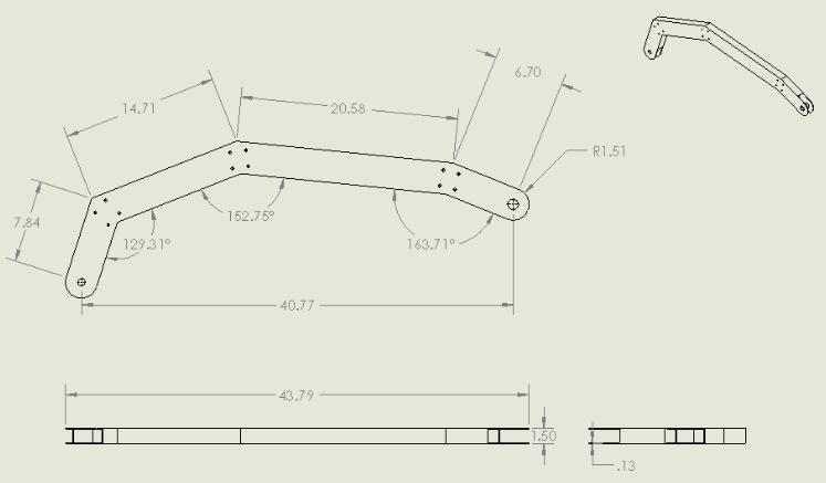
100 Shaft Boom 92


101 Appendix D: Manufacturing Process Operation Side View of milling the Base with the help of Tom in the MQP Lab Vertical Band Saw to cut of the Slider Parts Using the Vertical Band Saw to Cut the Back Wheel Frame 93
102 Appendix E: Charge for Labor The table below is the charge for labor required for the production of the Medical Lifting Device if it were to be mass produced by a factory. These are all rough estimates for each process in both time and cost. In conclusion, the Medical Lifting Device could be inserted into the market for a total price of $1, Part Name 1 Manufactured Component Time Spent to Complete (Time to Prepare Machine is Included.) Cost 60 min = $45 Base 1 Cutting Length 5 min. 2 Two Drill Holes 15 min. 3 Cutting Slots 1 hr. 4 Corner Radiuses 10 min. 5 Drill Pocket Hole 15 min. 6 Pocket for Shaft 1 hr. Total Time 2 hrs. 45 min. = 165 min. $ Right Leg Back 1 Face Cut 5 min. 2 Two Drill Holes 15 min. 3 Cutting Slots 1 hr. 4 End face needs to be rounded 15 min. Total Time 1 hr. 35 min. = 95 min. $ Left Leg Back 1 Face Cut 5 min. 2 Two Drill Holes 15min. 94
103 3 Cutting Slots 1 hr. 4 End face needs to be rounded 15 min. Total Time 1 hr. 35 min. = 95 min. $ Right Train 1 Cutting Slots 30 min. 2 Drill Front and Back Holes 15 min. 3 Face Cut 10 min. 4 Round Edges 10 min. 5 Drill the Vertical Holes 15 min. 6 Tap the Vertical Holes 20 min. Total Time 1 hr. 40 min. = 100 min. $ Left Train 1 Cutting Slots 30 min. 2 Drill Front and Back Holes 15 min. 3 Face Cut 10 min. 4 Round Edges 10 min. 5 Drill the Vertical Holes 15 min. 6 Tap the Vertical Holes 20 min. Total Time 1hr. 40 min. = 100 min. $ Train Tubing x2 1 Face Cut 10 min. 2 Thread on Either Sides of the Pipe 20 min. Total Time 30 min. $
104 Left Base 1 Face Cut 5 min. 2 Vertical Drill Hole 15 min. 3 Horizontal Drill Hole 15 min. 4 Cutting Slots 1 hr. 5 Corner Radius 10 min. Total Time 1hr. 45 min. = 105 min. $ Right Base 1 Face Cut 5 min. 2 Vertical Drill Hole 15 min. 3 Horizontal Drill Hole 15 min. 4 Cutting Slots 1 hr. 5 Corner Radius 10 min. Total Time 1 hr. 45 min. = 105 min. $ Left Leg Slider 1 Face Cut 5 min. 2 Milling the Top 30 min. 3 Milling a side 30 min. 4 Vertical Drill Hole (Tongue) 15 min. 5 Horizontal Drill Hole (Pin) 15 min. 6 Vertical Wheel Drill Hole 15 min. 7 Cutting the Tongue Slot 5 min. 8 Corner Radius 10 min. Total Time 2 hr. 5 min. = 125 min. $
105 Right Leg Slider 1 Face Cut 5 min. 2 Milling the Top 30 min. 3 Milling a side 30 min. 4 Vertical Drill Hole (Tongue) 15 min. 5 Horizontal Drill Hole (Pin) 15 min. 6 Vertical Wheel Drill Hole 15 min. 7 Cutting the Tongue Slot 5 min. 8 Corner Radius 10 min. Total Time 2 hr. 5 min. = 125 min $ Shaft 1 Face Cut (5 Angle) 5 min. 2 Dowel Pin Holes x4 15 min. 3 Cutting Slots 30 min. 4 End face needs to be rounded 10 min. Total Time 60 min $ Boom 1 Face Cut (Varying Angles) 10 min. 2 Two Drill Hole 15 min. 3 Cutting Slots 30 min. 4 End face needs to be rounded 10 min. 5 Weld Segments Together 2 hr. Total Time 3 hrs. 5 min. = 185 min $
106 Lower Hydraulic Pump Support 1 Face Cut 5 min. 2 Two Drill Hole 10 min. 3 Threaded Holes 10 min. 4 Cutting Side Cuts 15 min. 5 Drill Pin Hole 10 min. 6 Corner Radius 5 min. Total Time 55 min. $91.67 Upper Hydraulic Pump Support 1 Face Cut 5 min. 2 Varying Angles 15 min. 3 Threaded Holes 30 min. 4 Cutting Side Cuts 5 min. 5 Corner Radius 5 min. Total Time 60 min. $ Total Cost: $1, for 23 hrs. 25 min. ($45 per hour) $2, for 23 hrs. 25 min. ($100 per hour) 98
107 Appendix F: LabView Program The screenshots below are the LabView Program used to conduct the testing on the Medical Lifting prototype. The four images below are the Block Diagram where one can note the connections for the commands needed to properly achieve results. 99

108 100


109 Below is a screenshot of the Front Panel where the calibration takes place. Here are located the start, record and off buttons that help gather the data points. 101
110 Appendix G: Base Strain Testing Results The graphs below illustrate the data gathered when the loads were applied onto the prototype. Using the Excel file, the average and standard deviations were calculated. Above each graph are the degrees in which the test was run, the average and the standard deviation. Note that for each run, 20lbs., 45lbs. and 100lbs. were loaded separately onto the Medical Lifting prototype. 102
111 103
112 Appendix H: Leg Strain Testing Results The graphs below illustrate the data gathered when the loads were applied onto the prototype. Using the Excel file, the average and standard deviations were calculated. Above each graph are the degrees in which the test was run, the average and the standard deviation. Note that for each run, 20lbs., 45lbs. and 100lbs. were loaded separately onto the Medical Lifting prototype. 104

113 105

114 Appendix I: Pin Support Strain Testing Results The graphs below illustrate the data gathered when the loads were applied onto the prototype. Using the Excel file, the average and standard deviations were calculated. Above each graph are the degrees in which the test was run, the average and the standard deviation. Note that for each run, 20lbs., 45lbs. and 100lbs. were loaded separately onto the Medical Lifting prototype. 106
115 107
116 Appendix J: Boom Strain Testing Results The graphs below illustrate the data gathered when the loads were applied onto the prototype. Using the Excel file, the average and standard deviations were calculated. Above each graph are the degrees in which the test was run, the average and the standard deviation. Note that for each run, 20lbs., 45lbs. and 100lbs. were loaded separately onto the Medical Lifting prototype. 108
117 109

118 Appendix K: Aluminum Mechanical Properties 110
VHA Safe Patient Handling and Mobility Algorithms (2014 revision) Algorithm 4: Reposition in Chair: Wheelchair, Dependency Chair or Other Chair
 Algorithm 4: Reposition in Chair: Wheelchair, Dependency Chair or Other Chair") VHA Safe Patient Handling and Mobility Algorithms (2014 revision) Algorithm 1: Transfer To/From Seated Positions: Bed to Chair, Chair to Chair, Chair to Exam Table Algorithm 2: Lateral Transfer to/from
VHA Safe Patient Handling and Mobility Algorithms (2014 revision) Algorithm 1: Transfer To/From Seated Positions: Bed to Chair, Chair to Chair, Chair to Exam Table Algorithm 2: Lateral Transfer to/from
This report summarizes the ergonomic risk assessment conducted at a Hospital August 2001.
 Naval Facilities Engineering Command Ergonomic Risk Assessment for Naval Hospital, Labor & Delivery - Patient Transport INTRODUCTION This report summarizes the ergonomic risk assessment conducted at a
Handling the Bariatric Patient: Ergonomic Issues HoverTech International All Rights Reserved
 Handling the Bariatric Patient: Ergonomic Issues 2014 Plan Where are you going? 2014 2011 HoverTech International All Rights Reserved Ergonomics Defining Ergonomics Ergonomics is NOT: Buzzword, passing
Mechanical Ceiling/Floor Transfer (Hoyer)
") Mechanical Ceiling/Floor Transfer (Hoyer) o With 2 or more people determine who is going to be the leader and who is going to assist. o Explain the process to the patient and what is required for them
Mechanical Ceiling/Floor Transfer (Hoyer) o With 2 or more people determine who is going to be the leader and who is going to assist. o Explain the process to the patient and what is required for them
Chapter 14. Body Mechanics and Safe Resident Handling, Positioning, and Transfers
 Chapter 14 Body Mechanics and Safe Resident Handling, Positioning, and Transfers Body Mechanics Body mechanics means using the body in an efficient and careful way. It involves: Good posture Balance Using
Safe moving and handling guidance
 Safe moving and handling guidance An overview of moving and handling in the care industry, from legislation to practical tips, written by Frances Leckie, editor of the Independent Living website Contents:
Redefining Patient Handling. prevention
 Redefining Patient Handling prevention Joerns Healthcare, manufacturer of Hoyer products, is committed to providing a complete line of top quality equipment to the healthcare industry. The name Hoyer is
HSC 360b Move and position the individual
 CASE STUDY: Planning a move Shireen is the care worker for Mrs Gold, who is 80. Shireen needs to move Mrs Gold from a bed into a chair. Mrs Gold is only able to assist a little as she has very painful
Caution! triangles are used to warn of situations that demand extra care and attention.
 OctoStretch Instruction guide English 7EN160104-01 2009-07-07 Applies to the following models: OctoStretch Prod. No. 3156055 OctoStretch Balance Prod. No. 3156056 OctoStretch is intended for lifting and
PURPOSE: POLICY: FACTS:
 Revised Date: 03/13/2018 Page 1 of 14 PURPOSE: It is responsibility of each individual employed at the Black Hills Surgical Hospital to promote employee health and safety. In order to maintain and promote
Redefining Patient Handling. prevention
 Redefining Patient Handling prevention Joerns Healthcare, manufacturer of Hoyer products, is committed to providing a complete line of top quality equipment to the healthcare industry. The name Hoyer is
UNDERSTANDING COEFFICIENT OF FRICTION AND WHY OTHER SLIDE SHEET PROPERTIES ARE ALSO IMPORTANT
 August 2016 UNDERSTANDING COEFFICIENT OF FRICTION AND WHY OTHER SLIDE SHEET PROPERTIES ARE ALSO IMPORTANT by Jamar Health Products, Inc. ABSTRACT BACKGROUND: Discussions about slide sheets, which are meant
The Ergonomics of Patient Handling
 The Ergonomics of Patient Handling March 22, 2005 1 Major Healthcare Trends Pressure to Control Costs Emphasis on Reducing Length of Stay Attention to Patient Safety Focus on Nursing Staff Retention/Recruitment
Ave 2 Birthing Bed. Welcome to the world
 Ave 2 Birthing Bed Welcome to the world The journey begins AVE 2 is an ideal platform for safely performing labor exercises with an extra low heigh of 23.6 inches. The innovative design of the AVE 2 brings
Overexertion injuries in long- term care
 Overexertion injuries in long- term care Mike Lampl, M.S, CPE Ohio Bureau of Workers Compensation (BWC) 614-995 995-1203 www.ohiobwc.com Ohio BWC Nursing Home Stats 566 policies with manual #8829 with
CARENDO ERGONOMIC HYGIENE CHAIR WITH UNIQUE CARE RAISER
 CARENDO ERGONOMIC HYGIENE CHAIR WITH UNIQUE CARE RAISER Carendo 3 THE TRUE PROBLEM SOLVER Showering is becoming more common within long term care, but existing methods are uncomfortable for the resident
2010 Innovative Uses and Tips for Safe Patient Moving Equipment: Safe Patient Moving: the Keys to the Kingdom: Learning Objectives
 2010 Innovative Uses and Tips for Safe Patient Moving Equipment: Better Care, Less Wear Safe Patient Moving: the Keys to the Kingdom: Learning Objectives A. Describe what Consistency Communication Collaboration
Facility and Equipment Assessments and Hands-on Equipment Training
 SPH Training Series Session 2 Facility and Equipment Assessments and Hands-on Equipment Training Western New York Council on Occupational Safety & Health (WNYCOSH) This material was produced under grant
Lift Repositioning and Turning Accessory Operating Instructions
 The EZ Way line of Repositioning and Turning Accessories was designed to aid caregivers in effectively turning patients, repositioning patients, elevating patients over a bed to change bed linen, and weighing
ConCerto Shower trolley
 Concerto Shower Trolley Concerto 3 Assisted showering with extra care More and more healthcare facilities are turning to showering for residents personal hygiene routines. Concerto offers a safe, wellproven
NHS Training for Physiotherapy Support Workers. Workbook 15 Transfers
 NHS Training for Physiotherapy Support Workers Workbook 15 Transfers Contents Workbook 15 Transfers 1 15.1 Aim 3 15.2 Learning outcomes 3 15.3 Lying sitting transfer 4 15.4 Teaching a patient to move up
Opera. With people in mind
 Opera With people in mind Opera... ARJO a prime mover in the handling revolution ARJO patient handling and moving equipment is firmly established as the most acceptable for today's ergonomics-conscious
More comfortable childbirth
 Labour, delivery and recovery bed More comfortable childbirth MATERNITY More comfortable childbirth Three different Optima bed s available Optima labour, delivery and recovery bed family offers more comfortable
Guidelines. Homes. Ergonomics. Musculoskeletal Disorders. for Nursing. for the Prevention of
 Guidelines for Nursing Homes Ergonomics for the Prevention of Musculoskeletal Disorders Table of Contents Executive Summary 2 Section I. Introduction 4 Section II. A Process for Protecting Workers 6 Provide
R E C L I N E R S E A T I N G
 RECLINER EATING upporting Connections. At Nurture, we believe every interaction between the patient and caregiver matters. To help support these vital connections, we observe what can be better within
JOB TASK ANALYSIS. Stanislaus County. CEO-Recruitment Unit
 JOB TASK ANALYSIS Employer: Occupation: Company Contact: Stanislaus County Supervising Public Health Nurse CEO-Recruitment Unit Date: May 2001 Analysis Provided By: Lyle Andersen, PT, CWCE Andersen & Baim
CARMINA BARIAtRIC shower CoMMode ChAIR
 CARMINA BARIAtRIC shower CoMMode ChAIR with people in mind 2 Carmina A SAfe Showering Solution for bariatric care Carmina is a new solution designed to improve assisted hygiene routines in bariatric environments.
INTRODUCTION. AUTHORIzATION A Word of Caution
 RxOnly TAbLE Of CONTENTS Product Terminology................. 2 Important Information Specifications.................... 2 Introduction...................... 3 Authorization..................... 3 Customer
Safe Patient Handling:
 Safe Patient Handling: The Hazards of Immobility Prepared by : Learning Objectives Discuss the opportunity for quality improvement using SPHM practices Discuss expected positive patient outcomes using
Eleganza 3XC. Designed for ICU
 Eleganza 3XC Designed for ICU Benefits of Eleganza 3XC 2 LINET Eleganza 3XC Everything needed to save lives Prevention of pulmonary and cardiac complications Falls protection and pressure ulcer prevention
Birthing Bed AVE 2. Welcome to this world child
 Birthing Bed AVE 2 Welcome to this world child The journey begins Birthing bed AVE 2 is perfectly suitable for labor, delivery, recovery and postpartum in the childbirth phases, so women in labor and their
*Before instructing class carefully review Transfer Sheet User Guide*
 Training Guide (0908) Barton Transfer Sheets *Before instructing class carefully review Transfer Sheet User Guide* Introductory Phase Introduction and Statement of Intent 1. Welcome attendees and introduce
DIAMOND-TUFTED EXTENDED HEADBOARD BED COLLECTION
 WIDTH THICKNESS SIDE S WIDE 36"H QUEEN 88K 124N 36 36 124N 4 - - - 2 2 2 80Kx60K 1K 10K 0-129 WIDE 36"H KING 88K 145 36 36 145 4 - - - 2 2 2 80Kx76K 1K 10K 0-269 149 WIDE 36"H CAL KING 92K 133 36 36 133
Quality Care is. Partners in. In-Home Aides. Assisting with ambulation and using assistive devices: - March
 In-Home Aides Partners in Quality Care - March 2015 - In-Home Aides Partners in Quality Care is a monthly newsletter published for AHHC of NC and SCHCA member agencies. Copyright AHHC 2015 - May be reproduced
Simply Practical. The Hill-Rom CareAssist ES Hospital Bed
 Simply Practical. The Hill-Rom CareAssist ES Hospital Bed CareAssist ES Bed: Simply practical. The CareAssist ES bed is our foundational Med-Surg bed. We ve designed it especially for busy caregivers who
Streamline. IV Suspension System. Reliabilit y Versatilit y Cost Savings. Reliability Versatility Cost Savings
 Streamline IV Suspension System Reliabilit y Versatilit y Cost Savings Reliability Versatility Cost Savings From this Patient transport requires up to three or more caregivers and often multiple IV poles
Bariatric Bed Shown with options
 2nd Generation nhancements Ø Sliding patient surface for easier expansion/retraction to 54 width Ø Fold Down Foot ails Ø Plexiglas Windowed, otating Head ails Ø Narrower Frame for improved doorway clearance
TESTING APPLICATION STANDARD (TAS) IMPACT TEST PROCEDURES
 IMPACT TEST PROCEDURES") TESTING APPLICATION STANDARD (TAS) 201-94 IMPACT TEST PROCEDURES 1. 2. Scope: 1.1 This protocol covers procedures for conducting the impact test of materials as required by Section 1626 of the Florida
TESTING APPLICATION STANDARD (TAS) 201-94 IMPACT TEST PROCEDURES 1. 2. Scope: 1.1 This protocol covers procedures for conducting the impact test of materials as required by Section 1626 of the Florida
Ergonomics Issues In Paramedic Duties: A Case Study. Steve Morrissey Ergonomics Consultant Oregon OSHA Consultation
 Ergonomics Issues In Paramedic Duties: A Case Study Steve Morrissey Ergonomics Consultant Oregon OSHA Consultation Introduction Non-binding ergonomic consultation with a large ambulance service in the
PSA 2017 Paper Improved Tornado Missile Risk Analysis Using Nonlinear Finite Element Analysis of Nuclear Power Plant Structures.
 Improved Tornado Missile Risk Analysis Using Nonlinear Finite Element Analysis of Nuclear Power Plant Structures PSA 2017 Paper 21892 September 25, 2017 1 Improved Tornado Missile Risk Analysis Using Nonlinear
LF1090 BARIATRIc. USeR MANUAL. LF1090-INS-LAB-RevD GF Health Products, Inc.
 LF1090 BARIATRIc PATIeNT LIFT USeR MANUAL LF1090-INS-LAB-RevD12 2012 GF Health Products, Inc. Read this manual before operating your Patient Lift. Save this manual for future use. The most current version
The Role of the Emergency Medical Technician Lifting and Moving Patients Safely
 CHAPTER 6 The Role of the Emergency Medical Technician Lifting and Moving Patients Safely Lifts, Drags, Takedowns, and Carries Transporting Patients Safely Transportation Equipment This chapter focuses
Park Nicollet Health Services
 file://c:\documents and Settings\cruzal\Desktop\Safe Patient Handling\Content_1\01MainMenu_1\01MainMenu_1.html Introduction Main menu 1 of 23 1 / 1 Welcome to the Applying Principles of Safe Patient Handling
Solutions to Challenges Associated with Bariatric Patients
 Solutions to Challenges Associated with Bariatric Patients Manon Labreche, PT, CEAS 2, CHC Injury Prevention Manager Tampa General Hospital mlabreche@tgh.org Lynda Enos, RN, MS, COHN-S, CPE Ergonomics
User Guide (0108) Barton Ceiling Track Lift
 Barton Ceiling Track Lift") User Guide (0108) Barton Ceiling Track Lift 1 Lift Features 1. Lift capabilities and design features; 2. Lift operation; Ceiling Track Lifts are designed to withstand the rigors of daily institutional
User Guide (0108) Barton Ceiling Track Lift 1 Lift Features 1. Lift capabilities and design features; 2. Lift operation; Ceiling Track Lifts are designed to withstand the rigors of daily institutional
PUSH for FACT # 1. Quality Patient Care! What are the Facts about Safe Patient Handling and Movement?
 # 1 : PATIENTS AND THEIR CAREGIVERS ARE INJURED BY MANUAL LIFTING TASKS Safe Patient Handling and Movement: A policy and practice that creates a safe environment for patients and healthcare workers by
66CF1005 Certificate lifting equipment with new delivery Pag. 64/03
 Estil Spur-Gear Chain Hoists Estil Link Chain Hand-Lever Hoists Estil Steel wire hoist and lashing devises. Estil Trolleys for manual and electrical hoists Estil Beam clamps for temporarty lifting points
To provide the appropriate way of carrying and/or moving of a patient ensuring the patient's safety
 SUBJECT: PATIENT CARRYING METHODS PURPOSE: To provide the appropriate way of carrying and/or moving of a patient ensuring the patient's safety PROCEDURE: 1. Universal Carry - The Universal Carry is a method
Module 6: Client Moving Techniques * Terms marked by an asterisk are defined in the Glossary
 Module 6: Client Moving Techniques * Terms marked by an asterisk are defined in the Glossary 6.1 Introduction Module 1 introduced the moving task as a consistent set of steps used to move a client. At
CNA Training Advisor
 CNA Training Advisor Volume 12 Issue No. 6 JUNE 2014 REDUCING THE RISK OF WORK-RELATED INJURIES Without taking the necessary precautions and adhering to the proper body mechanics, CNAs could be harmed
CARINO. with people in mind
 CARINO Height adjustable hygiene chair with people in mind A BETTER ALTERNATIVE FOR DAILY HYGIENE For many residents and patients assisted hygiene routines consist of being showered on a fixed-height shower
LF1090 BARIATRIC PATIENT LIFT
 LF1090 BARIATRIC PATIENT LIFT USER MANUAL LF1090-INS-LAB-RevG15 2005 GF Health Products, Inc. Read this manual before operating your Patient Lift. Save this manual for future use. CONTENTS 1 INTRODUCTION...
Expand your possibilities
 Expand your possibilities 2 Why choose A-dec We've been partnering with doctors for over 45 years to produce reliable, creative dental solutions. Here are just a few of the reasons why so many dental professionals
Hill-Rom Advanta 2 Bed Tips Simply Intuitive FOR COMPLETE INSTRUCTIONS ON HOW TO OPERATE THE ADVANTA 2 BED, SEE USER S MANUAL.
 Hill-Rom Advanta 2 Bed Tips Simply Intuitive FOR COMPLETE INSTRUCTIONS ON HOW TO OPERATE THE ADVANTA 2 BED, SEE USER S MANUAL. 1 Three-Mode Bed Exit System (Patient Position Monitor) The Bed Exit Alarm
Ergonomic (MSI) Risk Factor Identification and Assessment Ergonomics Risk Assessment Project. Task List Worksheet
 Risk Factor Identification and Assessment Ergonomics Risk Assessment Project. Task List Worksheet") Ergonomic (MSI) Risk Factor Identification and Assessment Department/Work Area: Maternity Specific Location: Occupation: RN Contact Name: Task List Worksheet Job Summary: Provides nursing care to patients
Ergonomic (MSI) Risk Factor Identification and Assessment Department/Work Area: Maternity Specific Location: Occupation: RN Contact Name: Task List Worksheet Job Summary: Provides nursing care to patients
Safe Patient Movement and Mobility Improving Outcomes for Patients and Employees. Objectives. Your Presenter. Vision
 Presented by: Janice Homola, ARM Senior Consultant Loss Prevention Services Workers Compensation Services Safe Patient Movement and Mobility Improving Outcomes for Patients and Employees Your Presenter
Soteria Strains Safe Patient Handling and Mobility Program Guide
 Soteria Strains Safe Patient Handling and Mobility Program Guide Section 2 Identifying Hazards and Assessing Risk V1.0 edited August 21, 2015 A provincial strategy for healthcare workplace musculoskeletal
Chapter 6 MANHATTAN COLLEGE
 Chapter 6: Manhattan College 79 Chapter 6 MANHATTAN COLLEGE School of Engineering Mechanical Engineering Department Riverdale, NY 10471 Principal Investigator: Daniel W. Haines (718) 862-7145 dhaines@mcs1.rlc.mancol.edu
SMP 385MT. Solutions Start Here... Solutions Start Here USER & MAINTENANCE MANUAL
 Solutions Start Here... SMP 385MT Solutions Start Here www.smpcanada.com SMP Canada 10 Sims Crescent, Richmond Hill Ontario, L4B-1K9 Canada Tel: (905) 764-7767 Fax: 1-866-627-9798 support@smpcanada.com
Thank you for purchasing the Actuator Systems NextBolt fingerprint deadbolt.
 PREFACE Thank you for purchasing the Actuator Systems NextBolt fingerprint deadbolt. Please read the documentation carefully before installation & use. The manual details all installation procedures and
Safe Patient Handling & Early Mobility
 Safe Patient Handling & Early Mobility This workshop is awarded two (2) contact hours through the New York State Nurses Association Accredited Provider Unit. The New York State Nurses Association is accredited
Chapter 17 Part 2. Comfort & Safety. Information you will need
 Chapter 17 Part 2 Body Mechanics Comfort & Safety Protect the person s skin from friction and shearing when moving and lifting (these can cause infection and pressure ulcers. Reduce friction and shearing
OAK HILL COMMUNITY PROGRAMS JOB DESCRIPTION PROGRAM SUPERVISOR GENERAL PURPOSE
 OAK HILL COMMUNITY PROGRAMS JOB DESCRIPTION PROGRAM SUPERVISOR GENERAL PURPOSE The Program Supervisor works in Community Residences, Day Programs, Supported Employment Programs and Supported Living Programs
CArEnDO ElECtrIC HyGIEnE CHAIr
 CARENDO electric hygiene chair with people in mind Working methods can put carers health at risk 80 70 60 50 40 30 20 10 Studies have confirmed that carers assisting with washing in bed or ing using a
Patient Transfer Technologies In the Home
 Patient Transfer Technologies In the Home Lori Peculis, PT, ATP Molly Boland, MS, ATP, RET Assistive Technology Unit University of Illinois at Chicago S Transfer Assistance in the Home: Who? Where? Why?
SECTION P: RESTRAINTS
 SECTION P: RESTRAINTS Intent: The intent of this section is to record the frequency over the 7-day look-back period that the resident was restrained by any of the listed devices at any time during the
Using Body Mechanics
 Promotion of Safety Using Body Mechanics Muscles work best when used correctly Correct use of muscles makes lifting, pulling, and pushing easier Prevents unnecessary fatigue and strain and saves energy
showering solutions Create a safe, efficient and dignified care environment
 showering solutions Create a safe, efficient and dignified care environment with people in mind Real needs and everyday reality Every day, bed-baths compromise the dignity and safety of patients and caregivers,
EasyCare Maximizing Care, Comfort and Safety
 EasyCare Maximizing Care, Comfort and Safety Meeting the Challenges of Change For over 125 years, Joerns has been at the forefront of innovative healthcare technologies. At Joerns, we continue to design
Introduction. Welcome to Human Care.
 Convertible Chairs Introduction We produce and provide lifting solutions for people with special needs. Our products are made to serve as a natural part of life to all our users. Human Care has a proud
Activity 3: TRANSFER TO A WHEELCHAIR Future tense
 Contextualized Grammar I-BEST SUN Path Curriculum Unit for Nursing Assistant with ESL Support - Page 1 of 10 Activity 3: TRANSFER TO A WHEELCHAIR Future tense Learning Goal(s) Demonstrate the indirect
Occupational Safety for the Nursing Profession
 Occupational Safety for the Nursing Profession Presentation by Risk Management Division Centers for Long Term Care, Inc. Steve Spainhouer, OSHT, ASSE The US Department of Labor states that working in a
Taking Care Of Your Back Manual Handling. Clinical Skills
 Clinical Skills Taking Care of Your Manual Handling Course devised by the Clinical Skills Team Training delivered by Cardiff & Vale UHB (Health, Safety & Environment Unit) Aims & Outcomes Aims & Outcomes
Leicestershire Partnership NHS Trust. Moving and Handling Level 2 Update 2018/19
 Leicestershire Partnership NHS Trust Moving and Handling Level 2 Update 2018/19 Introduction Welcome to your Moving and Handling Level 2 Update for 2018/2019. This session forms part of an on-going programme
FlexoStretch. Product Description. Instruction Guide
 FlexoStretch Instruction Guide English 7EN160176-02 2009-07-07 Applies to the following models: FlexoStretch Prod. No. 3156057 Product Description FlexoStretch is intended for lifting and transferring
Safe handling of bariatric patients and residents September 2015
 RiskTopics Safe handling of bariatric patients and residents September 2015 Introduction As the world population average body weight continues to rise, due primarily to lifestyle choices and high caloric/fat
Safe Handling and Mobility. Program Development Guide
 Safe Handling and Mobility Program Development Guide 2 Safe Handling and Mobility Program Development Guide Table of Contents 4 Overview 5 Leadership Commitment and Responsibility 6 Accountability 7 Safe
James R. Gage Center for Gait and Motion Analysis
 James R. Gage Center for Gait and Motion Analysis Thank you for your assistance. If you need help or have any questions, please contact the Center for Gait and Motion Analysis Staff at (651) 229-3868.
Affinity Four Birthing bed Delivering Safety
 Affinity Four Birthing bed Delivering Safety The perfect combination of safety and ease-of-use In labour and delivery, every second counts. Caregivers must be able to respond quickly and easily, especially
Introduction. Welcome to Human Care.
 Convertible Chairs Introduction We produce and provide lifting solutions for people with special needs. Our products are made to serve as a natural part of life to all our users. Human Care has a proud
TAHOE CITY PUBLIC UTILITY DISTRICT Job Description
 TAHOE CITY PUBLIC UTILITY DISTRICT Job Description Job Title: Department: Utilities Supervised By: Utilities Superintendent FLSA Status: Non-Exempt Revised as of: January 2015 JOB SUMMARY To oversee and
Introducing the. Yesterday s challenge Today s solution. innova.uk.com
 Introducing the Yesterday s challenge Today s solution innova.uk.com What s Inside Introduction to Innova TM 03 Introducing the Integralift TM 04 The Concept 06 Configure your Integralift TM 08 Integralift
THIS PAGE INTENTIONALLY LEFT BLANK
 THIS PAGE INTENTIONALLY LEFT BLANK DEPARTMENT OF THE ARMY OFFICE OF THE CHIEF OF ARMOR MCGINNIS-WICKAM HALL 1 KARKER STREET SUITE 6600 FORT BENNING, GEORGIA 31905-4500 ATZK-AR 14 February 2017 MEMORANDUM
MMO
 MMO 3500 www.mmomedical.fr MMO 3500 The MMO 3500 bedframe is equipped with 3 segment side-rails. It has been spefically developed to offer a high level of autonomy to the patients, whilst guaranteeing
Safe Patient Lifting Guide
 Safe Patient Lifting Guide Mangar Health Established in 1981, Mangar Health is a world leader in the design, manufacture and supply of inflatable moving and handling equipment. We are an award-winning
9/17/2015. Bed Rail Safety A Clinical Process Guideline. Background. Federal Nursing Home Reform Act
 Bed Rail Safety A Clinical Process Guideline Laura Funsch, RN, BSN, MS, Director of Regulatory Strategy Background Safety hazards related to bed rail use have been realized since 1990. Michigan s initial
Bed Rail Safety A Clinical Process Guideline. Laura Funsch, RN, BSN, MS, Director of Regulatory Strategy
 Bed Rail Safety A Clinical Process Guideline Laura Funsch, RN, BSN, MS, Director of Regulatory Strategy Background Safety hazards related to bed rail use have been realized since 1990. Michigan s initial
BED RAIL SAFETY 9/15/2015. A Clinical Process Guideline. Background. Federal Nursing Home Reform Act
 BED RAIL SAFETY A Clinical Process Guideline Laura Funsch, RN, BSN, MS Director of Regulatory Strategy, LeadingAge Michigan Background Safety hazards related to bed rail use have been realized since 1990.
Development of SPH and ISO implemented in the United States
 Development of SPH and ISO implemented in the United States REFERENCES: ISO/TR 12296 Ergonomics: Manual Handling of People in the Healthcare Sector [Reference #: ISO/TR 12296:2012(E)] An edited summary
ENTERPRISE with people in mind
 ENTERPRISE 9000 Intensive Care Hospital Bed with people in mind DEDICATED TO PATIENT CARE A BED YOU CAN DEPEND UPON The needs of your critical care patients are challenging and complex. Which is why you
Simply Intuitive. The Hill-Rom Advanta 2 Bed
 Simply Intuitive. The Hill-Rom Advanta 2 Bed The Care Grip patient egress assist handle is designed to facilitate safer bed entry and exit by providing ergonomically correct leverage for patients. WE LISTENED
HELICOPTER MECHANIC, HELICOPTER MECHANIC SUPERVISOR, 3749
 HELICOPTER MECHANIC, 3742 4-16-93 HELICOPTER MECHANIC SUPERVISOR, 3749 Summary of Duties: Repairs, overhauls, inspects, maintains, services, cleans, and returns City owned helicopters and fixedwing aircraft
Section 5 General Policies Work, Health and Safety Policy. The Gums Childcare Centre Policies
 The Gums Childcare Centre Policies Section 5 General Policies 3.14 Work, Health and Safety Policy Background 1. The Gums Childcare Centre is committed to ensuring a safe and healthy working and learning
KwickScreen is the best solution I have seen to help solve the problems of space management in healthcare.
 1 KwickScreen is the ultimate in Flexible Space Management. Versatile, durable and perfect for a wide number of applications throughout the healthcare environment and beyond. KwickScreen is the best solution
OR Positioning and Pressure Injury Prevention. September 13, Ann N. Tescher, APRN CNS, PhD, CCRN, CWCN Debra L.
 OR Positioning and Pressure Injury Prevention September 13, 2017 Ann N. Tescher, APRN CNS, PhD, CCRN, CWCN Debra L. Fawcett, PhD, RN 2017 National Pressure Ulcer Advisory Panel www.npuap.org NPUAP Mission
POSITION DESCRIPTION Paramedic
 Revised Date: September 2009 Page: 1 of 3 POSITION SUMMARY: Reporting to the Field Supervisor, is responsible for responding to requests for ambulance service and delivering medical care to victims of
Velino. by Haelvoet HOSPITAL - NURSING HOME FURNITURE
 Velino by Haelvoet HAELVOET NV L. BEKAERTSTRAAT 8, 8770 INGELMUNSTER, BELGIUM T +32 (0) 51 48 66 95 F +32 (0) 51 48 73 19 INFO@HAELVOET.BE WWW.HAELVOET.BE HOSPITAL - NURSING HOME FURNITURE Velino perfect
Introduction. Welcome to Human Care.
 Healthcare Beds Introduction We produce and provide lifting solutions for people with special needs. Our products are made to serve as a natural part of life to all our users. Human Care has a proud history
NATIONAL TRANSPORTATION SAFETY BOARD WASHINGTON, D.C. MISSILE SELF DESTRUCT PERFORMANCE STUDY
 Docket No. Exhibit No. SA-516 22E NATIONAL TRANSPORTATION SAFETY BOARD WASHINGTON, D.C. MISSILE SELF DESTRUCT PERFORMANCE STUDY (23 page) NATIONAL TRANSPORTATION SAFETY BOARD Office of Research and Engineering
Bed Rail Entrapment Risk Notification Guide
 Bed Rail Entrapment Risk Notification Guide EN NOTICE TO EQUIPMENT PROVIDER: These instructions, in their entirety, must be provided to the patient, the patient s family and/or the patient s primary day-to-day