Main catalog. System pro M compact Surge and lightning protection solutions with QuickSafe technology
|
|
|
- Lindsay Bond
- 5 years ago
- Views:
Transcription

1 Main catalog System pro M compact Surge and lightning protection solutions with QuickSafe technology


2
3 System pro M compact Surge and lightning protection solutions with QuickSafe technology Presentation 3 1 OVR surge protective devices - IEC version 31 OVR surge protective devices - UL version Index TXH000375C001 - Edition May 015 ABB Surge and lightning protection solutions 1
4 1 ABB Surge and lightning protection solutions
5 Presentation Panorama 4 1 Surge and lightning protection solutions ABB expertise 6 Causes of transient overs 7 Origins of surges - Electrical operations on the distribution grid 10 General information on lightning 11 Protecting installations 1 Products Standards, IEC QuickSafe technology 14 Selection of surge protective devices 15 Surge protective device disconnectors 18 Installation and wiring of SPDs in an electrical switchboard 19 Example of an electrical switchboard protected by ABB surge protection solutions Mode of surge protection 3 Coordination and wiring principals 4 General wiring diagrams 5 Selection tool TNC network 30 / 400 V 6 TNC-S network 30 / 400 V 7 TT network 30 / 400 V 8 IT network 30 V without neutral 9 TNC, TNS - TT networks 30 / 400 V 30 ABB Surge and lightning protection solutions 3
 from 1.5 to 100 ka. Exposed building to lightning surges shall be protected with Type 1 or Type 1+ surge protective devices (SPDs).")
 must have at least a Type 1 SPD in the main distribution board.")
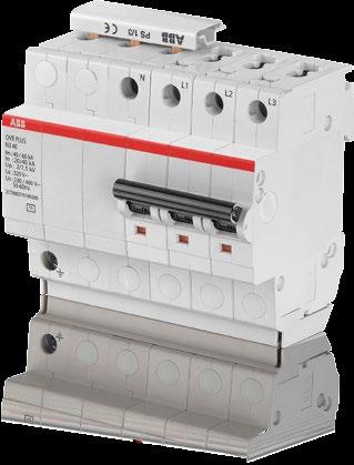
 Sub-distribution board installation Prolonged life time of sensitive equipment Autoprotected surge protective devices with the OVR Plus range.")


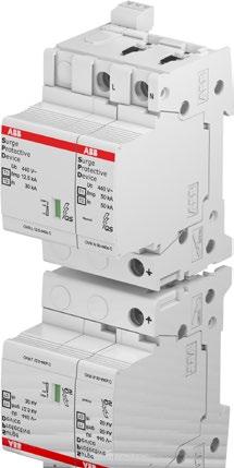
6 Panorama 1 OVR Type 1 and Type 1+ main entrance lightning protection Surge and lightning protection (LPZ 0 to LPZ 1 and ) Protection of the installation against direct lightning Impulse discharge (Iimp) from 1.5 to 100 ka. Exposed building to lightning surges shall be protected with Type 1 or Type 1+ surge protective devices (SPDs). With a high impulse discharge capacity (Iimp), they are located at the service entrance of the installation to avoid the destruction of the main switch board. Building protected against lightning with an external lightning protection (simple rod, meshed cage or ESE) must have at least a Type 1 SPD in the main distribution board. OVR Type and OVR Plus surge protective devices Surge protection (LPZ 1 to...) Sub-distribution board installation Prolonged life time of sensitive equipment Autoprotected surge protective devices with the OVR Plus range. Most of the equipment sustain repetitive transient surges. Generated by indirect lightning strikes or by industrial environment, these transient overs deteriorate and drastically reduce the life time of sensitive equipment like computers. Located in the sub-distribution boards of the installation, as close as possible to the equipment to protect, they offer a reliable and safe surge protection. OVR PV and OVR WT specific surge protection solutions Dedicated SPDs for solar and wind application Surge and lightning protection from LPZ 0 to LPZ Cost saving in avoiding down time of installations. Due to their high exposure to lightning and their specific electrical configuration, solar and wind turbine installations require a dedicated surge and lightning protection which take into consideration their specificities, high DC s for solar and high repetitive peak s for wind turbines. The use of standard surge protection on such installation may lead to down time or even destruction of the installation. A bit of history M. François Soulé creates the Soulé company First SPD by Soulé using Silicon Carbide Invention of the first Early Streamer Emission Terminal, type Pulsar, by Hélita and CNRS Soulé purchases the Hélita company to offer a complete lightning and over solution Split between MV, HV and Low Voltage activities. Soulé sales non-core businesses. 193 The External Lightning protection company Hélita is created First Din Rail SPD with Metal Oxide Varistor (MOV) SPD with thermal disconnection and end of life indication New Wavy design and phase + neutral version. CTC438001S001 4 ABB Surge and lightning protection solutions
 Certified according to NF C 17-10 September 011.")
, it can kill, injure and damage.")
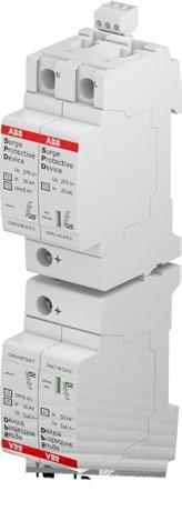
7 1 OVR TC dataline protection Complete range from 6 to 00 V DC RJ bases. OPR external air terminal lightning protection Early streamer emission air terminal Complete autonomy High efficiency (radius of protection Rp) Certified according to NF C September 011. In order to prevent data losses in Data Centers or to protect flow-meters in water treatment plans, a special range of surge protectors for Data Application has been developed. Lightning is one of the most spectacular meteorological phenomena. Generated by the interaction of clouds elements (water and ice), it can kill, injure and damage. Building and equipment installed in exposed areas should be protected by an external air terminal. 000 Soulé is purchased by Entrelec. 004 First Type 1 Spark gap technology. ABB branded. 010 Launch of the System Pro M Compact range with Safety Reserve System as option. Unique product in the market back then. 015 QuickSafe launch 001 Entrelec is purchased by ABB. Soulé & Hélita become the Low Voltage lightning protection experts within the ABB group. 009 Self Protected SPD, with MCB or fuse. 014 Launch of the OVR for Street Lightning protection. CTC438001S001 ABB Surge and lightning protection solutions 5
 or an indirect lightning strike (8/0 µs impulse wave) to be able to test the")
8 Surge and lightning protection solutions ABB expertise 1 With its experience gained over the last few decades, ABB is using its technological expertise for lightning and over protection. The ABB laboratory with several generators can simulate the impact of a direct lightning strike (10/350 µs impulse wave) or an indirect lightning strike (8/0 µs impulse wave) to be able to test the surge protective devices. Through its wide product range, ABB is able to offer a complete solution to protect power and low networks. Seminars are organized to the needs of all professionals: design offices, consultants, distributors, electricians, sales staff. These training sessions combine practical and theoretical aspects and cover a varied range of topics such as direct impact protection and over protection. The ABB laboratory is able to handle tests on AC surge protective devices (SPDs) according to IEC (011) and on PV SPDs according to EN (013). High power lightning generators Standardized electrical waves 8/0 µs and 10/350 µs. Maximum shock 100 ka for the two waves, superposed on the electrical network. Stored energy 800 kj. 00 kv generator 1./50 impulse wave Maximum 00 kv Stored energy 10 kj. Combination wave generator Electrical tests Climatic tests High Speed Camera Standardized 8/0-1./50 impulse wave 30 kv maximum 15 ka maximum Stored energy 5 kj. 75 V, A and 440 V, A short-circuit AC testing V, 1000 A short-circuit DC testing. Ageing and damp heat tests. Up to frames/s ABB laboratory at Bagnères-de-Bigorre, France CTC438003S001 6 ABB Surge and lightning protection solutions


9 Surge and lightning protection solutions Causes of transient overs Transient surges represent the main cause of electrical devices failure and loss of productivity. They are the result of lightning strikes, switching operations on the electrical network or parasitic interferences. Nowadays, in all the sectors (residential, commercial and industrial), in the data center industry, they rely on their computer systems. A downtime in one of these computer systems, due to transient surges, can have catastrophic consequences. Loss of operation, loss of service, loss of data and of productivity involve, in most of the cases, huge consequences which are, by far, higher than the costs of the equipments for protection against overs. 1 The use in electronic systems of more and more sensitive electronic equipments, with interconnection and complexity of the nets increase the probability of damages caused by the transient overs. CTC43800S001 ABB Surge and lightning protection solutions 7
: 6% Not identified: 1% Damages to electronic equipment. Analysis conducted in France for residential segment by AVIVA, one of the largest insurance company (www.aviva.")
10 Surge and lightning protection solutions Causes of transient overs 1 Network defect, 50 Hz temporary over: 15% Short circuit: 6% Over: 61 % (lightning discharge and switching operations) Other causes (damage, fire...): 6% Not identified: 1% Damages to electronic equipment. Analysis conducted in France for residential segment by AVIVA, one of the largest insurance company ( At the same time, the following trends shall be underlined: Increasing use of electronic systems such as computers, telecommunication equipment. Over consequences are of huge importance in a global economy based and relying on power networks and information systems Therefore, the protection against lightning and transient overs is now a fundamental aspect of our electrical system configuration. Electronic equipment more and more sensitive. With miniaturization process of circuits and components in electronic, modern equipment is now more incline to be damaged from transient overs Interconnection and complexity of system networks. In big cities, the effects induced by lightning are very high due to the fact that they can be propagated by the service lines over many kilometers. Furthermore, the use of lots of industrial equipment generates disturbances, transient overs, on the lines that damage expensive equipment. Transient over effect CTC43800S001 8 ABB Surge and lightning protection solutions
11 Surge and lightning protection solutions Causes of transient overs Transient overs due to direct lightning effects When a lightning strikes directly a building equipped with a lightning protection system (LPS), the lightning is dissipated to the ground through the down conductors. However, the transient over can be propagated into the building through the earthing of the electrical installation. This type of direct effect can cause fire, damage the internal installation and the equipment or even worse can injury living beings. The same with a lightning strike on external line connected to the building, which can, through the cables, create fire and destruction of the internal electrical installation. 1 Lightning strike on an external air terminal or on the building Lightning strike on an overhead line connected to the building Transient overs due to indirect lightning effects Transient overs can also be the effect of an indirect lightning strike close to the building or close to external lines connected to the building. In that case, the electromagnetic field created by the lightning will generate resistive and inductive couplings. As a consequence, these can cause serious malfunction or damages to the internal installation or equipment. Lightning strike near a building Lightning strike near an overhead line Transient overs due to switching operations Switching overs are less powerful and destructive than transient surges caused by lightning. However, they occur much more frequently, causing premature ageing of the equipment. These overs can in fact result in severe damage to electronic circuit and need to be effectively countered to avoid expensive downtime and maintenance costs. CTC438004S001 ABB Surge and lightning protection solutions 9
12 Surge and lightning protection solutions Origins of surges - Electrical operations on the distribution grid 1 The switching of breakers, transformers, motors and inductive loads in general or the sudden modification of loads causes sudden variations (di/dt), generating transient surges. They are less energetic than surges caused by lightning, but they are much more frequent and are damaging as they are generated directly in the power supply network. Their brief duration, the sharp rising edge and the peak value (which can reach several kv) leads to premature wear of electronic equipment. 1 i = 1 U i = 0 U U (V) U (V) t t Switching of breakers 1- closed circuit - opening of circuit Order of magnitude of the disturbances. E Surge C D Representation of the different disturbances on the electricity supply grid in AC A B Duration of the temporary phenomenon > 00 ms Duration of the transitory phenomenon < 1 ms t (ms) A - Harmonics B - Micro-interruptions C - Surges from switching D - Indirect lightning strikes E - Direct lightning strikes From the point of view of over surges, direct lightning strikes carry the highest risk. Lightning surge 30 V 50 Hz TOV Switching surge Rms : 30 V Transient over Purpose of SPD Temporary over Enemy of SPD Where to find more OVR Practical guide for the protection against surges, 1TXH000309C001. CTC438005S ABB Surge and lightning protection solutions
13 Surge and lightning protection solutions General information on lightning The stress caused by a lightning strike on the network almost always represents the most important parameter when selecting a SPD (Surge Protective Device). 1 Intensity of direct lightning strikes The French institute Meteorage conducted a series of measurements of the intensity of over 5.4 million lightning strikes in France over the ten years from 1995 to 004. The following curve summarizes the cumulative frequency of the lightning strikes with respect to their intensity, according to the results of this enormous measuring campaign: 1.7% of the lightning strikes are greater than 100 ka 0.33% of the lightning strikes are greater than 150 ka 0.1% of the lightning strikes are greater than 00 ka 0.03% of the lightning strikes are greater than 50 ka. These are values measured in France, however the intensity of lightning has no correlation with the geographical position, and equivalent results would be obtained by performing the same analysis in other countries. What does, however, characterize each geographical area is the density value by geographical area Ng (described on the following page). Cumulative frequency 100 % 80 % 60 % 40% of lightning strikes are greater than 0 ka (i.e. 60% of lightning strikes are less than 0 ka) 40 % 0 % 5 % 0 % 5% of lightning strikes are greater than 60 ka (i.e. 95% of lightning strikes are less than 60 ka) Lightning strike intensity Cumulative frequency of lightning strikes - positive and negative - with respect to their intensity. Data supplied by Meteorage ( Where to find more OVR Practical guide for the protection against surges, 1TXH000309C001. CTC438006S001 ABB Surge and lightning protection solutions 11
14 Surge and lightning protection solutions Protecting installations End-of-life safety... And when it occurs 1 On average, a 40 ka Type SPD has a lifespan of twenty years, but some may last thirty, and others only five! The data refer to the frequency of lightning strikes according to IEC 6305 standards, to SPD lifespan tests according to IEC and to basic statistics. A statistical question The lifespan of a SPD depends on its resilience connected to its rated discharge In, but also to the number of times lightning strikes near the system each year On average, a 40 ka SPD worldwide will reach the end of its life after twenty years Given the large number of SPDs installed, statistics tell us that a SPD reaching the end of its life is far from an improbable occurrence; some SPDs (premature) could reach the end of their lives in the first few years of the system's operation... End-of-life probability Premature What happens to each of the SPDs I've installed over the years? First years of life 0 years of life Over 0 years of life CTC438007S001 0 years Long-lasting Expected lifetime of SPD The replacement cartridges allow surge protection to be renewed when one of the SPDs reaches the end of its life-cycle. 1 ABB Surge and lightning protection solutions
15 Surge and lightning protection solutions Products Standards, IEC The new IEC :011 is similar to the EN :01 and is the standard for Low-Voltage Surge Protective Devices. These standards exist since the nineties and have gone through different releases improving them. In the last release not only the evaluation of the product performances is under focus, but the stress on safety evaluation. Regarding performances, this new edition recognizes the possibility to evaluate and certify a SPD under multiple categories, option not considered in the previous editions. So in order to certify an SPD under the Type 1 and Type category, two different tests need to be performed to validate the features under each one of them. What's new in IEC/EN :01? New test procedure which takes into account the failure behavior of protective equipment in the event of an overload, or when the service life has expired The Type 1 operating duty test is conducted with a higher than that specified in the previous standard Recognition of the mixed types, as Type 1+ and Type +3, this allows as to certify the product with more than one category. 1 Until now, the safety of the SPD was verified reproducing situations that represent the working conditions of the SPD, as for example, the short-circuit test or the temporary over- test. According to the new edition of the standard, new tests reproducing the potential interruption of the Neutral conductor and the different modes of end of life of the SPD are performed. Thermal Disconnection Temperatures measured at the disconnection point of the MOV ma 30 8 These two additional tests are a real Plus on safety management and they are a guarantee for the final user that the installation will not suffer any stress in case of the end of life of the SPD. The new QuickSafe range has been specially developed to answer to these new requirements. All this reducing the stress on the back-up protection device. The new QuickSafe technology allows to comply with the end of life tests thanks to a patented internal disconnection system, this systems disconnects the internal circuit before the internal components (MOVs) go into short-circuit. The advantage for the customer is that the product is selfprotected up to higher values of and this allows to install back-up protection elements with higher rated, as these elements will only intervene in the rear case of a short-circuit on site together with a sudden End of Life of the SPD (this happens when for example the SPD is hit by a higher than it's Imax). You will find the tables on page 18 indicating the maximum back-up rated MCB or fuse to use to guarantee the coordination. This new technology allows as well to increase the prospective withstand short-circuit at the point of the installation up to Isccr = 100 ka with a back up protection of maximum rated of 15 A (for OVR T QS and OVR T-T3 QS) and 160 A (for OVR T1-Ts QS and OVR Ts QS). In simple words, the new OVR QuickSafe can be used in 99.9% of standard installations and becomes an easy replacement to any other SPD ranges. Temperature ( C) ma 0 ma 5 ma 10 ma Pro M (non QuickSafe ) Time (min) QuickSafe Current level Here we can see different curves representing the behavior of the actual range (blue curve ) and the new QuickSafe range (red curve ), for the same level of (the green line represent the evolution of the with the time, as specified by the IEC ). These curves represent the temperature INCREASE that the MOV suffers when being tested under these values of for the indicated time. These are NOT absolute temperature, but relatives ones As you can see with the black arrows, the time to guarantee the disconnection fo the same level of has been reduced by 6 minutes And even better, as you can see with the orange arrows, the maximum reached temperature required to guarantee the disconnection is lower, from 108 to 76 C Runaway (ma) CTC438009S001 ABB Surge and lightning protection solutions 13

16 Surge and lightning protection solutions QuickSafe technology 1 In case of an end of life of an MOV in normal conditions, the passing through the MOV increases progressively creating a quick temperature increase. This phenomenon will slowly damage the MOV itself until it gets into shortcircuit. This phenomenon is called a thermal runaway. In order to avoid such thermal runaway we have added a thermal disconnection that will detect this temperature increase and will open the circuit. This disconnection QuickSafe is directly welded into the surface of the MOV to allow a very fast detection of the raise of temperature, it will react opening the circuit when the temperature achieve the levels considered hazardous for the installation. This disconnection is guaranteed by a metallic arm linked to a spring guaranteeing a quick disconnection. This is a phenomenon that happens only after thousands of surge protection interventions in average. Most of SPDs get changed during the installation updates before this ever happens. This is the ultimate protection at the very end of life of the SPD Here the disconnection system in Close position. During the test simulating and end of life of the SPD, the SPD has to bear a high that forces a passing through it. In this example, the passing is 10 A. Few seconds later, the MOV achieves a temperature that is high enough to melt the special metallic alloy that guarantees the contact and the mechanical position of the metallic arm. This releases the metallic arm pushed far away by the junction spring. The tension in the spring is enough to quickly push up the arm and guarantee the insulation of the MOV. The speed of this movement is a key feature to interrupt the electric arc that will appear between the MOV core and the metallic arm. This movement combined with the characteristics of the MOV will guarantee the complete extinction of the arc. At the end of this movement, the metallic arm will stop without any bouncing. There is no risk of a new electric arc development. At this moment, the MOV has not suffered any thermal runaway, so it is not in short-circuit. The distance between between the MOV electrode and the metallic arm guarantees an insulation of over 6000 V, avoiding any risks for the installation. CTC438009S ABB Surge and lightning protection solutions
17 Surge and lightning protection solutions Selection of surge protective devices The IEC standard introduced the concept of lightning protection zones (LPZ) to help in selecting the correct surge protection. This concept ensure the gradual reduction by stages of the energies and over caused by lightning or switching operations. This logic of coordination in the protection is what we call the "stepping protection". Lightning protection zones description (IEC ): It consists in dividing a building in several volumes: the protection zone. The objective is to ensure that the LPZ gives enough protection to the equipment inside this zone. To do so, SPDs are installed at the protection zone boundaries. Each time an SPD is installed, a new protection zone is created. 1 External Zones: LPZ 0A Unprotected zone outside the building subject to direct lightning strikes and therefore may have to handle to the full lightning and lightning electromagnetic field LPZ 0B Zone protected against direct lightning strikes by external air terminal and where the threat is the full lightning electromagnetic field. Current impulse: The 10/350 and 8/0 impulse waves are used in the Class I and Class II SPDs tests. The first number gives the rising time of the impulse to reach 90% of the peak level and the second number gives the time to half value in micro-seconds (µs). Internal Zones: Zones inside the building which are protected against direct lightning flashes. LPZ 1 Zone subject to partial lightning or surge s. Type I SPDs shall be installed at the boundary between LPZ 0A and LPZ 1 to reduce the entrance of lightning s through power lines LPZ...n Zone where the surge is limited by sharing and where the surge energy is reduced by additional surge protection like SPDs. Type SPDs are installed at the boundaries of each zone, i.e. LPZ 1 and LPZ, LPZ and LPZ 3, etc. 90 % 50 % 10 % 90 % 10/ /0 μs 50 % 10 % External lightning protection system 8 0 μs LPZ 0A r Antenna LPZ 0B r: Radius of the rolling sphere LPZ 1 LPZ Power lines LPZ 3 Communication lines CTC438008S001 ABB Surge and lightning protection solutions 15
18 Surge and lightning protection solutions Selection of surge protective devices 1 Protection level and impulse withstand The protection level (U p) of the SPD shall be selected according to the level of over given to the equipment to be protected against transient surge. Each equipment is rated with an impulse withstand (U w) depending on its category. An equipment is protected if its U w is greater than the expected transient over between the live conductors and earth (common mode). If not, an SPD must be installed. The SPD is protecting the equipment if its protection level (Up), which is calculated under the nominal (In), is equal or lower to the impulse withstand of the equipment: U p/f U w The IEC defines the required impulse withstand as described in the table below: Categories* U n Examples 30 / 400 V 400 / 690 V I 1500 V 500 V Equipment containing particularly sensitive electronic circuits: computer workstations, computers, TV, HiFi, Video, Alarms, etc. household appliances with electronic programmers, etc. II 500 V 4000 V Domestic electrical equipment with mechanical programmers, portable tools, etc. III 4000 V 6000 V Equipment subject to special requirements. Distribution panels, switches, breakers, etc. IV 6000 V 8000 V Equipment for use at the origin of the installation. Electricity meters, circuit-breakers, etc. * IEC Selection of surge protective device The selection of the surge capacity of SPDs depends on the surge and lightning risk, determined by the risk analysis according to IEC If there is a direct lightning risk on the structure, a Type 1 SPD will have to be installed at the service entrance and Type and Type 3 SPDs in the sub-distribution boards, as close as possible to the equipment to protect. If there is not a direct lightning risk on the structure (no external protection, no aerial lines connected) a Type SPD can be installed at the service entrance and in the sub-distribution boards. A Type 1 SPD will be selected by its maximum impulse (I imp) characteristics, and a Type SPD by its nominal (I n) and maximum discharge (I max) characteristics. Basic example for a Type 1 SPD calculation (IEC ): Lightning Protection Level calculated: LPL I Maximum peak : I=00 ka Assumption: perfect sharing Number of connected service supply (earthing, water pipe): m= Network configuration: 3 Phases + Neutral (n=4). Total (I imp)/phase = I x 0.5 / (m x n) = 00 x 0.5 / ( x 4) = 1.5 ka 1 1 Lightning strike on an external air terminal or on the building Lightning strike near a building 3 Lightning strike on an overhead line connected to the building 4 Lightning strike near an overhead line LPL I: 00 ka L1 L L3 PEN 4 3 SPD Sensitive equipment SPD Connected service supply CTC438008S ABB Surge and lightning protection solutions

 system In case of surge exceeding the maximum capacity of the device, one of the MOVs could achieve the end of life, the surge")

.")
19 Surge and lightning protection solutions Selection of surge protective devices End of life indicator of the standard surge protective device This option enables indication of the surge protective device state via a mechanical indicator which changes from green to red as the surge protective device comes to end-of-life. When this occurs, the surge protective device must be changed as protection is no longer guaranteed. End of life of the surge protective device fitting Safety Reserve (s) system In case of surge exceeding the maximum capacity of the device, one of the MOVs could achieve the end of life, the surge protective device will switch to the Safety reserve position and the mechanical end of life indicator in the front of the product will switch to the intermediate position. Consequently, the user can see in advance that the protection features of the SPD are degradated, but still guaranteed and has more time to replace the cartridge, because in Safety reserve position the protection is still ensured due to the -stage disconnecting system. If the customer wants to be warned in case one of the MOVs achieves it's end of life and the product gets into Safety Reserve, the SPD has to be fitted with a Remote Auxiliary contact (TS). This Auxiliary Contact will change status as soon as one of the MOVs gets damaged. The combination of the Auxiliary contact (TS) and the Safety Reserve System allow to perform Preventive Maintenance, as the in formation about the degradation of the protection features will be received while the protection is still guaranteed, allowing for the schedule of maintenance activities while the site is still protected. End-of-life indicator standard SPD Normal Red Replace End-of-life End-of-life indicator with safety Reserve system Normal off In Reserve End-of-life NOTE: A faulty surge protective device does not interrupt continuity of service (if wired such that priority is given to continuity of service), it simply disconnects itself. But, the equipment is no longer protected. Wiring schematic alarm NOTE: Pluggable surge protective device cartridges have a foolproof system (Neutral cartridges different to Phase cartridges) preventing incorrect operations when replacing a cartridge. Surge protective device fitted with the auxiliary contact option Pluggable The pluggable feature of ABB surge protective devices facilitates maintenance. Should one or more worn cartridges need to be replaced, the electrical circuit does not have to be isolated nor do the wires have to be removed. res 1 Technical features of the integrated auxiliary contact Contacts information: Normally-opened (NO) / Normallyclosed (NC) Min. load: 1 V DC - 10 ma Max. load: 50 V AC - 1 A Connection cross-section: 1.5 mm². pro M compact range Auxiliary contact (TS) This function, achieved by wiring a 3-point 1 A volt-free contact, enables the operational state of the surge protective device to be checked remotely (maintenance premises). For standard products, the TS changes status when the cartridge needs to be replace, protection is not guaranteed. On products fitting the Safety Reserve (s) system, it indicates that one component of the cartridge is damaged, but the protection is still guaranteed. Max. discharge Imax 8/0 10 ka 0 ka 40 ka 80 ka 10 ka Impulse Iimp 10/ ka 5 ka s: with safety reserve P: pluggable device QS: QuickSafe Technology OVR T N s P TS QS BW Designation: T1: Type 1 SPD T1-T: Type 1+ SPD T: Type SPD T-T3: Type +3 SPD PLUS: Autoprotected SPD PV: Photovoltaic SPD TC: Dataline SPD WT: Wind turbine SPD Phases: Without: 1 pole L: poles 3L: 3 poles 4L: 4 poles N: 1 neutral 1N: 1 phase (left) - neutral (right) 3N: 3 phases (left) - neutral (right) N1: neutral (left) - 1 phase (right) N3: neutral (left - 3 phases (right) Max. operating Uc 600 V 440 V 350 V 75 V 150 V 75 V Auxiliary contact BW: Bottom Wiring CTC438013S001 ABB Surge and lightning protection solutions 17
20 Surge and lightning protection solutions Surge protective device disconnectors 1 Choice of backup protection Surge protective device must have disconnectors which are internal and external. Internal is the so called thermal disconnection which helps to disconnect the SPD at the end of life (varistors technology). External is the backup protection which can be an MCB or a fuse dedicated to the SPD protection in case of short circuit due to very high surge transient for example. or Designation Protection against indirect contact Protection against fault s Thermal protection Function Residual devices (RCDs) assure a protection to people and installation. When installed with SPDs they must be of selective type "S" to avoid nuisance tripping. In ABB portfolio you can choose the F00 S type range for a safer installation. Miniature circuit breakers (MCBs) or fuses protect the installation against overload and short circuit. They can be associated with SPDs for the backup protection in agreement with coordination installation rules. You can either choose MCBs from the S00 or S800 series or fuses from the E90 range. The thermal disconnection is an internal disconnection which is there to bring a safer protection to the equipment. ABB is always developing new patents and has developed a thermal disconnection mechanism specifically dedicated to PV installation with the OVR PV range for a better and safer protection. Type of Surge Protective Devices Circuit breaker maximum ratings* curve B or C Prospective short circuit at SPD location (Ip) Fuses maximum ratings* (gl - gg) Ip 6 ka Ip 10 ka Ip 5 ka Ip 50 ka Type 1 OVR T1 unpluggable S800S A fuse Iimp 5 ka / Ifi 7 ka Uc 55 and 440 V Type 1+ OVR T1+ unpluggable S800 S A fuse Iimp 5 ka / Ifi 15 ka Uc 55 V OVR T1+ unpluggable S800 S A fuse Iimp 15 ka / Ifi 7 ka Uc 55 V OVR T1-T pluggable QuickSafe Safety Reserve S800 S A fuse Iimp 1.5 ka / Ifi 7 ka Uc 75 V, 440 V Type OVR T pluggable S00 M - 16 S00 M A fuse Imax 15 ka Uc 75 V OVR T pluggable S00 M - 50 S00 M - 50 S00 P - 50 S800 S A fuse Imax 10 ka Uc 440 V OVR T pluggable QuickSafe S00-63 S00 M - 63 S00 P - 63 S800 S A fuse Imax 40 ka Uc 75, 350, 440, 600 V OVR T pluggable Safety Reseve QuickSafe S00-63 S00 M - 63 S00 P - 63 S800 S A fuse Imax 40 and 80 ka Uc 75, 440 V OVR T unpluggable S00 M - 50 S00 M - 50 S00 P - 50 S800 S A fuse Imax 0 and 40 ka Uc 150 V, 75 and 440 V Type +3 OVR T-T3 pluggable QuickSafe Imax 0 ka S00-63 S00 M - 63 S 00 P - 63 S 800 S A fuse Uc 75, 350, 440, 600 V Type 3 OVR T3 unpluggable Imax 10 ka Uc 75 V S00 M - 10 S00 M A fuse * Maximum ratings, must be in accordance with the installation to follow coordination rules with main or upstream short circuit protection(s). Service entrance SPDs Type 1 Type PE connection cable size 16 mm² 4 mm² CTC438014S ABB Surge and lightning protection solutions
21 Surge and lightning protection solutions Installation and wiring of SPDs in an electrical switchboard Connection distance 50 cm rule A lightning of 10 ka generates a drop of approximately 100 V in 1 m of cable due to the inductance of the conductor. Equipment protected by a SPD is therefore subject to a of U prot equal to the sum of: - Protection level of the SPD U p - Voltage at the terminals of the back-up protection U d - Voltage in the connections U 1, U, U 3 1 U prot = U p + U d + U 1 + U + U 3 To maintain the level of protection below the impulse withstand (U w) of the devices to be protected, the total length (L = L1 + L + L3) of the connecting cables must be as short as possible (less than 0.50 m). U1, L1 Back-up protection U d U, L U prot L SPD U p U3, L3 A: in this case L = L1 + L The length L3 has no effect on the protection of equipment. B: in this case L = L1 + L + L3 If the length of L3 is several meters, considering that every extra meter of wire increases the protection by 100 V, the protection loses a lot of effectiveness. It is necessary to pay attention to the actual length of the connections, which must be measured from the SPD's terminals to the point at which the cable is taken off as a spur from the main conductor. Here is an example which demonstrates the importance of the lengths of connections (for simplicity the diagram omits the backup protection). A SPD L3 L1 L Node Equipment to be protected B SPD L3 L1 L Node Equipment to be protected The equipment's earth connection must be distributed, starting from the connection of the SPD which protects it. CTC438031S001 ABB Surge and lightning protection solutions 19
22 Surge and lightning protection solutions Installation and wiring of SPDs in an electrical switchboard 1 In the case where the length of the connection (L = L1 + L + L3) exceeds 0.50 m, it is recommended to adopt one of the following steps: 1) Reduce the total length L: - By moving the installation point of the SPD in the switchboard; - Using V, or "entry-exit" wiring, which allows the lengths of the connections to be reduced to zero (it must, however, be ensured that the rated line is compatible with the maximum tolerated by the SPD's terminals); - In large switchboards, connect the PE coming in to an earth bar near the SPD (the length of the connection is only the spur off from this point, so a few cm); downstream of the connection point, the PE can be taken to the main earth bar. L1 = 0 SPD SPD Entry-exit wiring L = 0 Earth bar Main bar CTC43803S001 ) Choose a SPD with a lower level of protection U p Install a second SPD coordinated with the first as close as possible to the device to be protected, so as to make the level of protection compatible with the impulse withstand of the equipment. 0 ABB Surge and lightning protection solutions
23 Surge and lightning protection solutions Installation and wiring of SPDs in an electrical switchboard Electrical lines and connection area It is necessary to arrange the lines so that the conductors are as close as possible to each other (see figure) to avoid surges induced by inductive coupling of an indirect lightning strike with a large loop contained between the phases, the neutral and the PE conductor. 1 Cabling of protected and non-protected lines During installation, run the protected and non-protected wiring according to the instructions in the diagrams below. To avoid the risk of electromagnetic coupling between different types of wires, it is strongly recommended they be kept at a distance from one another (> 30 cm) and that when it is not possible to avoid them crossing, this needs to be performed at a right angle. Distance between two wires: Master circuit breaker Output feed Protected line Non-protected line Protected line Non-protected line SPD back-up protection D > 30 cm D < 30 cm Wires crossing: Crossing of wires at 90 Non-protected line Non-protected line Protected line Protected line Equipotential earthing It is fundamental to check the equipotentiality of the earths of all the equipment. The equipment's earth connection must also be distributed, starting from the connection of the SPD which protects it. This allows the connection distances and therefore the U prot to be limited. Earthing connection Section of the connections Wiring between active network conductors and the SPD The cable section must be at least the same as the upstream wiring. The shape of wiring is more important than the section. The recommended section for Main Board is 10 mm² for phase and Neutral and 16 mm² for earth. Wiring between the SPD and earth The minimum section is 4 mm² in the case where there is no lightning conductor, and 10 mm² in the case one is installed. It is nevertheless recommended to use a cable with a greater section to leave a safety margin, e.g mm section. CTC438033S001 ABB Surge and lightning protection solutions 1


24 Surge and lightning protection solutions Example of an electrical switchboard protected by ABB surge protection solutions 1 Main switch Node with connections to SPD and output feeds Output feed 1 Output feed Back-up protection (MCB) SPD surge protective device OVR Earth terminal with spur connections Rules followed by the installer: - Connection distances < 50 cm - Earth terminal in proximity to SPD - Back-up protection dedicated to the SPD - Protection installed upstream of RCDs - Reduction of the loop between the phases, neutral and PE CTC438034S001 ABB Surge and lightning protection solutions
25 OVR T1 5N OVR T1 5N OVR T OVR T OVR T OVR T OVR T OVR T OVR T OVR T OVR T OVR T OVR T OVR T OVR T OVR T Surge and lightning protection solutions Mode of surge protection Protection in common and/or differential mode Common mode Overs in common mode concern all neutral point connections. They occur between the live conductors and earth (e.g. phase/earth or neutral/earth). The neutral conductor is a live cable, as well as the phase conductors. This over mode destroys not only earthed equipment (Class I), but also non-earthed equipment (Class II) with insufficient electrical insulation (a few kilovolts) located close to an earthed mass. Class II equipment that is not situated close to an earthed mass is theoretically protected from this type of attack. Differential mode Overs in differential mode circulate between the live phase/phase or phase/neutral conductors. They can cause considerable damage to any equipment connected to the electrical network, particularly "sensitive" equipment. These overs concern TT earthing systems. They also affect TN-S systems if there is a significant difference in length between the neutral cable and the protective cable (PE). 1 Overs in common mode Overs in differential mode Different types of OVR configuration Either Common mode or differential mode of protection are required depending on the system configuration (IT, TNC, TNS, TT). For that purpose, you can find different OVR configuration (single pole, 3L, 4L, 1N, 3N). Common mode configurations (TNC networks) L1 L L3 L1 L L3 OVR T x 3 Ref.: CTB815101R8700 OVR T 3L 40-75s P QS Ref.: CTB815704R1800 Common and differential mode configurations (TNS, TT networks) L1 L L3 N L1 L L3 N 3 x OVR T Ref.: CTB815101R OVR T1 5 N Ref.: CTB815101R9700 or OVR T1 3N Ref.: CTB815101R8800 OVR T 3N 40-75s P QS Ref.: CTB815704R000 CTC438015S001 ABB Surge and lightning protection solutions 3
 of SPDs depends on many parameters: Type of equipment to be protected, the length of the connections to the SPDs, the length in")

26 Surge and lightning protection solutions Coordination and wiring principals 1 The SPD installed at the line entrance of an installation may not ensure an effective protection to the whole system. As a matter of fact, the selection of the protection level (U p) of SPDs depends on many parameters: Type of equipment to be protected, the length of the connections to the SPDs, the length in between the SPDs and the equipment to be protected. Coordination required if : The protection level (U p) of the SPDs is not low enough to protect the equipment. If the distance in between the SPDs and the equipment is >10 m. NOTE: The first SPD is diverting most of the surge to the ground, and the second SPD will ensure a good protection level to the equipment. It is what we call the stepping protection. SPDs coordination tables and minimum cable length Type 1 Iimp = 5 ka Type s QS 80/40 ka (10/350) (8/0) I fi = 50 ka Type 1 Iimp = 5 ka (10/350) I fi = 7 ka L > 0 m Type QS 40 ka (8/0) Type +3 QS 0 ka (8/0) Type 1+ Iimp = 15 ka (10/350) I fi = 7 ka Type 1+ T1-T Quicksafe Iimp = 1.5 ka L > 5 m Type QS 40 ka (8/0) Type +3 QS 0 ka (8/0) (10/350) Type s QS 80 ka (8/0) Type +3 QS 0 ka (8/0) L > 1 m CTC438016S001 4 ABB Surge and lightning protection solutions
27 Surge and lightning protection solutions General wiring diagrams Wiring diagrams according to IEC TNC networks 30 / 400 V TNC-S networks 30 / 400 V L1 L L3 PEN L1 L L3 N PE Equipment Equipment TNS networks 30 / 400 V TT networks 30 / 400 V IT networks 30 / 400 / 600 V L1 L L3 N PE L1 L L3 N L1 L L3 Equipment Equipment Equipment Wiring diagrams according to UL 1449 Single phase networks 10 / 40 / 77 V Split phase networks 40 / 10 V, 480 / 40 V L1 L1 N N G L G Delta networks 40 / 480 / 600 V Grounded Wye networks 08 Y / 10 V, 480 Y / 77 V, 600 Y / 347 V L1 L1 L L N L3 G L3 G High-Leg Delta networks 40 / 100 V HLD L1 L N L3 G CTC438017S001 ABB Surge and lightning protection solutions 5
28 OVR T1 OVR T OVR T OVR T Alarm Alarm Alarm OVR T OVR T OVR T Alarm Alarm Alarm Surge and lightning protection solutions Selection tool: TNC - 30 / 400 V network 1 Industry, commercial building Configuration 1 15 ka I p 50 ka Configuration I p 15 ka L1 L L3 PEN L1 L L3 PEN Main distribution board E933/15 E933/15 OVR T1 3L 5-55 TS Ref.: CTB815101R0700 > 10 meters cable > 10 meters cable Main distribution board 3 x OVR T TS Ref.: CTB815101R CTB815141R0700 (busbar) or OVR T1+ 3L 5-55 TS Ref.: CTB815101R4300 Sub-distribution board S * S * OVR T 3L 40-75s P QS Ref.: CTB815704R1800 Sub-distribution board OVR T 3L 40-75s P QS Ref.: CTB815704R1800 Ip: prospective short circuit of the power supply. * Must be according to the coordination rules with main or upstream short circuit protection(s). CTC438018S001 6 ABB Surge and lightning protection solutions
29 OVR OVR T1 T1 OVR T1 OVR OVR T T OVR OVR T T OVR OVR T T OVR OVR T T T OVR T OVR T OVR T OVR OVR T T OVR OVR T T OVR OVR T T OVR OVR T T OVR OVR T T OVR OVR T T OVR T OVR T OVR OVR OVR Surge and lightning protection solutions Selection tool: TNC-S - 30 / 400 V network Industry, commercial building 1 Configuration 1 15 ka I p 50 ka Configuration 7 ka I p 15 ka Configuration 3 I p 7 ka L1 L L3 N PEN L1 L L3 N PEN L1 L L3 N PEN Main distribution board E933/15* E933/15* E933/15* OVR T1 3L 5-55 TS Ref.: CTB815101R x OVR T TS Ref.: CTB815101R CTB815141R0700 (busbar) or OVR T1+ 3L 5-55 TS Ref.: CTB815101R x OVR T Ref.: CTB815101R0300 > 10 meters cable > 10 meters cable > 10 meters cable Sub-distribution board S * S * OVR T 3N 40-75s P TS QS Ref.: CTB815704R0800 OVR T 3N 40-75s P TS QS Ref.: CTB815704R0800 OVR Plus N3 40 Ref.: CTB803701R0300 > 10 meters cable > 10 meters cable > 10 meters cable S * Distribution outlet OVR T 1N 40-75s P TS QS Ref.: CTB815704R000 OVR Plus N1 40 Ref.: CTB803701R0100 OVR Plus N1 40 Ref.: CTB803701R0100 Ip: prospective short circuit of the power supply. * Must be according to the coordination rules with main or upstream short circuit protection(s). CTC438019S001 ABB Surge and lightning protection solutions 7
30 OVR T1 OVR T1 OVR T OVR T OVR T OVR OVR T T OVR T OVR T OVR T OVR T OVR T OVR T OVR T OVR T1 100 N OVR T OVR T OVR T OVR T OVR OVR Surge and lightning protection solutions Selection tool: TT - 30 / 400 V network 1 Industry, commercial building Configuration 1 15 ka I p 50 ka Configuration 7 ka I p 15 ka Configuration 3 I p 7 ka L1 L L3 N PEN L1 L L3 N PEN L1 L L3 N PEN Main distribution board > 10 meters cable E933/15* E933/15* E933/15* OVR T1 3N 5-55 TS Ref.: CTB815101R0700 > 10 meters cable 3 x OVR T TS Ref.: CTB815101R CTB815141R0700 (busbar) 1 x OVR T1 100N Ref.: CTB815101R0500 or OVR T1+ 3N 5-55 TS Ref.: CTB815101R00 > 10 meters cable OVR T1 3N Ref.: CTB815101R9000 Sub-distribution board S * S * OVR T 3N 40-75s P TS QS Ref.: CTB815704R0800 OVR T 3N 40-75s P TS QS Ref.: CTB815704R0800 OVR Plus N3 40 Ref.: CTB803701R0300 > 10 meters cable > 10 meters cable > 10 meters cable Distribution outlet S * OVR T 1N 40-75s P TS QS Ref.: CTB815704R000 OVR Plus N1 40 Ref.: CTB803701R0100 OVR Plus N1 40 Ref.: CTB803701R0100 Ip: prospective short circuit of the power supply. * Must be according to the coordination rules with main or upstream short circuit protection(s). CTC43800S001 8 ABB Surge and lightning protection solutions
31 OVR T1 OVR T OVR T OVR T OVR T OVR T OVR T Surge and lightning protection solutions Selection tool: IT - 30 V network without neutral Commercial, residential 1 The IT system has all live parts at the source isolated from earth or one part connected to earth with a high impedance. Configuration 1 I p 100 ka Configuration I p 15 ka L1 L L3 PEN L1 L L3 PEN Main distribution board S03 M-B 50* S03 M-C 50* Main distribution board E933/15* OVR T1-T 3L s P TS QS Ref.: CTB815710R x OVR T Ref.: CTB815101R9300 > 10 meters cable > 10 meters cable Sub-distribution board S * S * Sub-distribution board OVR T 3L s P TS QS Ref.: CTB815708R3500 OVR T 3L s P TS QS Ref.: CTB815708R3500 Ip: prospective short circuit of the power supply. * Must be according to the coordination rules with main or upstream short circuit protection(s). CTC43801S001 ABB Surge and lightning protection solutions 9
32 Surge and lightning protection solutions Selection tool: TNC, TNS - TT - 30 / 400 V networks 1 Residential With external conductive parts (external lightning protection air terminal, antenna...) or powered by aerial lines YES NO Neighbour with external lightning protection system (or generally with earthed extraneous conductive parts), or proximity of high points YES NO L < 50 m L > 50 m L1 L L3 PEN Distribution board TNC H > 0 m H < 0 m L < 50 m L > 50 m Configuration 1 With risk of direct lightning (external protection, aerial lines...) Configuration Without risk of indirect lightning, transient surges L1 L L3 PEN E933/15* 3 x OVR T Ref.: CTB815101R8900 or OVR T1+ 3L Ref.: CTB815101R9800 Distribution board TNC S03 M-B 40* S03 M-C 40* OVR T OVR T OVR T OVR T OVR T OVR T OVR T OVR T OVR T OVR T 3L 80-75s P QS Ref.: CTB815708R000 L1 N PEN L1 N PEN Distribution board TNS - TT S01 M-B 40 NA* S01 M-C 40 NA* OVR T Ref.: CTB815101R8900 OVR T1 5 N Ref.: CTB815101R9700 * Should be according to the coordination rules with installed main breakers. Distribution board TNS - TT OVR Plus N1 40 Ref.: CTB803701R0100 CTC4380S ABB Surge and lightning protection solutions
33 OVR surge protective devices - IEC version Selection tables 3 Ordering details and general technical data OVR Type 1 surge protective devices Single pole 38 TNC - 30 V networks 40 TNS - TT - 30 V - 1Ph+N networks 4 TNS - TT - 30 V - 3Ph+N networks 44 Single pole neutral 46 OVR Type 1+ surge protective devices Single pole 48 TNC - 30 and 400 V networks 50 TNS - TT - 30 and 400 V - 1Ph+N and 3Ph+N networks 53 OVR Type surge protective devices Single pole - 57 V networks 56 Single pole - Unpluggable - 10 V and 30 V networks 58 Single pole - Pluggable - 30 V networks 61 Single pole V networks 65 TNC - 30 V networks 68 TNC V networks 70 TNS - 30 V networks 7 TNS V networks 74 TNS - TT - 30 V - 1Ph+N networks 76 TNS - TT - 30 and 400 V - 3Ph+N networks 79 OVR Type -3 surge protective devices Single pole - 30 and 400 V networks 8 TNC - 30 V - 3Ph+PEN networks 84 TNS - TT - 30 V - 1Ph+N network 86 TT - 30 V and 400 V - 3Ph+N networks 88 OVR Type 3 surge protective devices TNS - TT - 30 V networks 90 OVR for applications OVR Plus autoprotected surge protective devices TNS - TT - 30 V networks 9 OVR Type -3 surge protective devices - StreetLight applications TT - TN - 30 V networks 94 OVR PV surge protective devices - Photovoltaic applications 96 OVR WT surge protective devices - Wind turbine applications 98 OVR TC surge protective devices - Dataline protection 100 Accessories for OVR 10 ABB Surge and lightning protection solutions 31
34 OVR surge protective devices - IEC version Selection tables Protected lines Impulse Type 1 - Unpluggable Max. discharge Nominal discharge Follow interrupting rating Voltage protection level Nominal Iimp 10 / 350 Imax 8 / 0 In Ifi Up Un Uc ka ka ka ka kv V V Max. cont. operating Type Order codes Uc 55 V OVR T CTB815101R OVR T CTB815101R / OVR T1 L 5-55 CTB815101R / OVR T1 L 5-55 TS CTB815101R / OVR T1 3L 5-55 CTB815101R / OVR T1 3L 5-55 TS CTB815101R / OVR T1 4L 5-55 CTB815101R / OVR T1 4L 5-55 TS CTB815101R OVR T1 1N 5-55 CTB815101R OVR T1 1N 5-55 TS CTB815101R / OVR T1 3N 5-55 CTB815101R / OVR T1 3N 5-55 TS CTB815101R / OVR T1 3N CTB815101R8800 Uc 440 V OVR T CTB815101R9300 Neutral OVR T1 5 N CTB815101R OVR T1 50 N CTB815101R OVR T1 100 N CTB815101R0500 Type 1+ Uc V OVR T1-T s P QS* CTB815710R OVR T1-T s P TS QS* CTB815710R / OVR T1-T 3L s P QS* CTB815710R / OVR T1-T 3L s P TS QS* CTB815710R / OVR T1-T 4L s P QS* CTB815710R / OVR T1-T 4L s P TS QS* CTB815710R / OVR T1-T 3N s P QS* CTB815710R / OVR T1-T 3N s P TS QS* CTB815710R OVR T1-T 1N s P QS* CTB815710R OVR T1-T 1N s P TS QS* CTB815710R OVR T CTB815101R / OVR T1+ 3N CTB815101R OVR T TS CTB815101R / OVR T1+ 3L 5-55 TS CTB815101R / OVR T1+ 4L 5-55 TS CTB815101R OVR T1+ 1N 5-55 TS CTB815101R / OVR T1+ 3N 5-55 TS CTB815101R00 Uc 440 V OVR T1-T s P QS* CTB815710R OVR T1-T s P TS QS* CTB815710R OVR T1-T 1N s P QS* CTB815710R OVR T1-T 1N s P TS QS* CTB815710R / OVR T1-T 3L s P QS* CTB815710R / OVR T1-T 3L s P TS QS* CTB815710R / OVR T1-T 3N s P QS* CTB815710R / OVR T1-T 3N s P TS QS* CTB815710R / OVR T1-T 4L s P QS* CTB815710R / OVR T1-T 4L s P TS QS* CTB815710R4000 Neutral OVR T1-T N 50-75s P QS* CTB815710R OVR T1-T N s P QS* CTB815710R5300 Cartridges OVR T1-T s C QS* CTB815710R OVR T1-T s C QS* CTB815710R OVR T1-T N 50-75s C QS* CTB815710R OVR T1-T N s C QS* CTB815710R700 * Products available end 015. CTC43807S001 3 ABB Surge and lightning protection solutions
35 Protected lines Impulse Max. discharge Nominal discharge Follow interrupting rating Voltage protection level Nominal Max. cont. operating Type Order codes Iimp 10 / 350 Imax 8 / 0 In Ifi Up Un Uc ka ka ka ka kv V V Type - Unpluggable Uc 150 V (±15%) 150 OVR T CTB80400R (±15%) 150 OVR T (x0) CTB80400R (±15%) 150 OVR T CTB80401R (±15%) 150 OVR T (x0) CTB80401R1700 Uc 75 V OVR T 0-75 CTB80400R OVR T 0-75 (x0) CTB80400R / OVR T 3L 0-75 CTB804600R / OVR T 3L 0-75 (x6) CTB804600R / OVR T 4L 0-75 (x5) CTB804600R OVR T CTB80401R OVR T (x0) CTB80401R / OVR T 3L CTB804601R / OVR T 3L (x6) CTB804601R / OVR T 4L CTB804601R / OVR T 4L (x5) CTB804601R1500 Uc 440 V OVR T CTB80400R OVR T (x0) CTB80400R OVR T CTB80401R OVR T (x0) CTB80401R100 Type - Pluggable Uc 75 V OVR T 0-75 P CTB803851R OVR T 0-75 P TS CTB803851R OVR T 0-75 P CTB80385R OVR T 0-75 P TS CTB80385R1600 Uc 75 V OVR T P QS CTB803871R OVR T P TS QS CTB803871R OVR T 40-75s P QS CTB815704R OVR T 40-75s P TS QS* CTB815704R / OVR T 3L P QS CTB803873R / OVR T 3L P TS QS CTB803873R / OVR T 3L 40-75s P QS* CTB815704R / OVR T 3L 40-75s P TS QS* CTB815704R / OVR T 4L P QS CTB803873R / OVR T 4L P TS QS CTB803873R / OVR T 4L 40-75s P QS* CTB815704R / OVR T 4L 40-75s P TS QS* CTB815704R OVR T 1N P QS CTB80397R OVR T 1N P TS QS CTB80397R OVR T 1N 40-75s P QS* CTB815704R OVR T 1N 40-75s P TS QS* CTB815704R / OVR T 3N P QS CTB803973R OVR T 3N P TS QS CTB803973R OVR T 3N 40-75s P QS* CTB815704R OVR T 3N 40-75s P TS QS* CTB815704R OVR T 80-75s P QS* CTB815708R OVR T 80-75s P TS QS* CTB815708R / OVR T 3L 80-75s P QS* CTB815708R / OVR T 3L 80-75s P TS QS* CTB815708R / OVR T 4L 80-75s P QS* CTB815708R / OVR T 4L 80-75s P TS QS* CTB815708R OVR T 1N 80-75s P QS* CTB815708R OVR T 1N 80-75s P TS QS* CTB815708R / OVR T 3N 80-75s P QS* CTB815708R OVR T 3N 80-75s P TS QS* CTB815708R0800 Neutral OVR T N P QS CTB803973R OVR T N 80-75s P QS* CTB815708R500 Cartridges OVR T C QS CTB803876R OVR T 40-75s C QS* CTB815704R OVR T N C QS CTB803876R OVR T 80-75s C QS* CTB815708R OVR T N 80-75s C QS* CTB815708R800 * Products available on end 015. (x5) packaging of 5 pieces. (x6) packaging of 6 pieces. (x0) packaging of 0 pieces. ABB Surge and lightning protection solutions 33 CTC43807S001
36 OVR surge protective devices - IEC version Selection tables Protected lines Impulse Max. discharge Nominal discharge Follow interrupting rating Voltage protection level Nominal Max. cont. operating Type Order code Iimp 10/350 Imax 8/0 In Ifi Up Un Uc ka ka ka ka kv V V Type - Pluggable Uc 350 V OVR T P QS CTB803881R OVR T P TS QS CTB803881R OVR T 1N P QS CTB80398R OVR T 1N P TS QS CTB80398R / OVR T 3L P QS CTB803883R / OVR T 3L P TS QS CTB803883R / OVR T 3N P QS CTB803983R / OVR T 3N P TS QS CTB803983R0500 Neutral OVR T N P QS CTB803973R OVR T N P QS CTB803983R1900 Cartridges OVR T C QS CTB803886R OVR T N C QS CTB803886R0000 Uc 440 V OVR T P QS CTB803871R OVR T P TS QS CTB803871R OVR T s P QS* CTB815704R OVR T s P TS QS* CTB815704R / OVR T 3L P QS CTB803873R / OVR T 3L P TS QS CTB803873R / OVR T 4L P QS CTB803873R / OVR T 4L P TS QS CTB803873R / OVR T 3N P QS CTB803973R / OVR T 3N P TS QS CTB803973R / OVR T 3N s P TS QS* CTB815704R OVR T s P TS CTB803951R OVR T s P QS* CTB815708R OVR T s P TS QS* CTB815708R / OVR T 3L s P QS* CTB815708R / OVR T 3L s P TS QS* CTB815708R / OVR T 4L s P QS* CTB815708R / OVR T 4L s P TS QS* CTB815708R / OVR T 3N s P QS* CTB815708R / OVR T 3N s P TS QS* CTB815708R3700 Neutral OVR T N s P QS* CTB815708R OVR T N P QS CTB803973R000 Cartridges OVR T s C QS* CTB815704R OVR T C QS CTB803876R OVR T s C QS* CTB815708R OVR T N C QS CTB803886R OVR T N s C QS* CTB815708R5700 Uc 600 V OVR T P TS QS CTB803881R / OVR T 3L P TS QS CTB803883R / OVR T 4L P TS QS CTB803883R5300 Uc 760 V / OVR T 3L /690 P CTB803853R / OVR T 3L /690 P TS CTB803853R4600 Cartridges / OVR T /690 C CTB803854R1100 * Products available end 015. CTC43808S ABB Surge and lightning protection solutions
37 Protected lines Impulse Max. discharge Nominal discharge Follow interrupting rating Voltage protection level Nominal Max. cont. operating Type Order code Iimp 10/350 Imax 8/0 In Ifi Up Un Uc ka ka ka ka kv V V Type -3 - Pluggable Uc 75 V OVR T-T P QS CTB803871R OVR T-T P TS QS CTB803871R OVR T-T3 1N 0-75 P QS CTB80397R OVR T-T3 1N 0-75 P TS QS CTB80397R / OVR T-T3 3L 0-75 P QS CTB803873R / OVR T-T3 3L 0-75 P TS QS CTB803873R / OVR T-T3 3N 0-75 P QS CTB803973R / OVR T-T3 3N 0-75 P TS QS CTB803973R1600 Neutral OVR T N P QS CTB803973R1900 Cartridges OVR T 0-75 C QS CTB803876R / OVR T N C QS CTB803876R0000 Uc 440 V OVR T-T P QS CTB803871R OVR T-T P TS QS CTB803871R / OVR T-T3 3N P QS CTB803973R1300 Neutral OVR T N P QS CTB803973R000 Cartridges OVR T C QS CTB803876R OVR T N C QS CTB803886R0100 Type 3 - Unpluggable Combination wave Uoc 6 kv OVR 1N CTB81391R / OVR 3N CTB813913R1000 Type - Autoprotected OVR PLUS N1 0 CTB803701R OVR PLUS N1 40 CTB803701R / OVR PLUS N3 0 CTB803701R / OVR PLUS N3 40 CTB803701R0300 (x0) packaging of 0 pieces. CTC43808S001 ABB Surge and lightning protection solutions 35
38 OVR surge protective devices - IEC version Selection tables Protected lines Impulse Max. discharge Nominal discharge Short circuit withstand Voltage protection level Nominal Max. cont. operating Type Order code Iimp 10/350 Imax 8/0 In Isscr/Iscpv Up Un Uc ka ka ka ka kv V V Type 1 - Pluggable - Photovoltaic applications Uc 600 V DC (Iscpv) OVR PV T P TS CTB803953R5700 Cartridges (Iscpv) OVR PV T C CTB803950R1000 Uc 1000 V DC (Iscpv) OVR PV T P TS CTB803953R6700 Cartridges (Iscpv) OVR PV T C CTB803950R1100 Type - Pluggable - Photovoltaic applications Uc 670 V DC (Iscpv) OVR PV P CTB803953R (Iscpv) OVR PV P TS CTB803953R5400 Cartridges 1+1 DC (Iscpv) OVR PV C CTB803950R0000 Uc 1100 V DC (Iscpv) 3.8 / OVR PV T P QS CTB804153R (Iscpv) OVR PV P CTB803953R (Iscpv) OVR PV P TS CTB803953R (Iscpv) OVR PV P TS BW (x30) CTB804153R1900 Cartridges 1+1 DC (Iscpv) OVR PV C CTB803950R0100 Uc 1500 V DC (Iscpv) OVR PV P BW CTB804153R (Iscpv) OVR PV P TS BW CTB804153R100 Cartridges (Iscpv) OVR PV C CTB803950R000 Type 1+ - Pluggable - Wind turbine applications Uc 690 V / OVR WT 3L 690 P TS CTB3540R0000 Cartridges OVR T C CTB803854R0400 Dataline protection - Pluggable Uc 7 V DC 1 pair OVR TC 06V P CTB80480R0000 Cartridges 1 pair OVR TC 06V C CTB80481R0000 Uc 14 V DC 1 pair OVR TC 1V P CTB80480R0100 Cartridges 1 pair OVR TC 1V C CTB80481R0100 Uc 7 V DC 1 pair OVR TC 4V P CTB80480R000 Cartridges 1 pair OVR TC 4V C CTB80481R000 Uc 53 V DC 1 pair OVR TC 48V P CTB80480R0300 Cartridges 1 pair OVR TC 48V C CTB80481R0300 Uc 0 V DC 1 pair OVR TC 00V P CTB80480R pair OVR TC 00FR P CTB80480R0500 Cartridges 1 pair OVR TC 00V C CTB80481R pair OVR TC 00FR C CTB80481R0500 Type -3 - Unpluggable - StreetLight applications OVR T-T3 N s SL CTB8000R OVR T-T3 N s SL (x0) CTB8000Z100 (x30) packaging of 30 pieces. CTC43809S ABB Surge and lightning protection solutions


39 CTC43809S001 ABB Surge and lightning protection solutions 37

40 OVR Type 1 surge protective devices - Single pole CSC40000F0013 Description Type 1 surge protective devices are designed to discharge high surges without any destruction of the installation. These surge protective devices are characterized by their capacity to withstand impulse with 10/350 µs wave form which simulate natural lightning. Type 1 SPDs can be installed at the entrance in the main switch board for a global protection of the electrical installation. OVR T1 Ordering details Protected lines Impulse Follow interrupting Voltage protection level Nominal Max. cont. operating Bbn Type Order code Weight Pkg (1 pce) Iimp 10/350 rating Ifi Up Un Uc ka ka kv V V EAN kg Follow interrupting rating 7 ka - Unpluggable OVR T CTB815101R Follow interrupting rating 50 ka - Unpluggable OVR T CTB815101R OVR T CTB815101R Main dimensions mm Type Width mm OVR T OVR T OVR T OVR T OVR T OVR T CTC430001S ABB Surge and lightning protection solutions
41 OVR Type 1 surge protective devices - Single pole General technical data Types OVR T OVR T OVR T with auxiliary contact (TS) Technology Spark-gap Spark-gap Spark-gap Electrical features Standard IEC / EN Type / test class T1 / I T1 / I T1 / I Protected lines Types of networks TNC - TNS - TT IT - TNC - TNS - TT TNC - TNS - TT Type of AC AC AC Nominal Un 30 V 400 V 30 V Maximum continuous operating Uc 55 V 440 V 55 V Maximum impulse Iimp (10/350) 5 ka 5 ka 5 ka Maximum impulse Tot. Iimp (10/350) 5 ka 5 ka 5 ka Nominal discharge In (8/0) 5 ka 5 ka 5 ka Follow interrupting rating Ifi 7 ka 50 ka 50 ka Voltage protection level Up at In.5 kv.5 kv.5 kv Voltage protection level Up at 3 ka 0.9 kv 1.3 kv 0.9 kv TOV (Temporary over) 650 V / 690 V / 0 V / withstand Ut (L-N: 5 s / N-PE: 00 ms) Response time 100 ns 100 ns 100 ns Residual IPE 1000 µa 10 µa 10 µa Short-circuit withstand capability Isccr 50 ka 50 ka 50 ka Backup protection Fuse (gg - gl) 15 A 15 A 15 A Circuit breaker (B or C curve) 15 A 15 A 15 A Pluggable cartridge No No No Integrated thermal disconnector State indicator Yes No No Safety reserve No No No Auxiliary contact (TS) No No No Installation Wire range (L, N, PE) Solid wire.5 50 mm².5 50 mm².5 50 mm² Stranded wire.5 35 mm².5 35 mm².5 35 mm² Stripping length (L, N, PE) 15 mm 15 mm 15 mm Tightening torque (L, N, PE) 3.5 Nm 3.5 Nm 3.5 Nm Auxiliary contact (TS) Contact complement Minimum load Maximum load Connection cross-section Miscellaneous characteristics Stocking and operating temperature C C C Degree of protection IP0 IP0 IP0 Fire resistance according to UL 94 V0 V0 V0 Dimensions mm h x w x d 85 x 17.8 x 70.8 mm 85 x 35.6 x 70.3 mm 85 x 35.6 x 64.8 mm inches h x w x d 3.35 x 0.7 x.79 in 3.35 x 1.4 x.77 in 3.35 x 1.4 x.55 in Dimensions with auxiliary contact (TS) mm h x w x d inches h x w x d CTC430001S001 ABB Surge and lightning protection solutions 39

42 OVR Type 1 surge protective devices TNC - 30 V networks OVR T1 3L 5-55 CSC40001F0013 Description Type 1 surge protective devices are designed to discharge high surges without any destruction of the installation. These surge protective devices are characterized by their capacity to withstand impulse with 10/350 µs wave form which simulate natural lightning. Type 1 SPDs can be installed at the entrance in the main switch board for a global protection of the electrical installation. Ordering details Protected lines Impulse Follow interrupting Voltage protection level Nominal Max. cont. operating Bbn Type Order code Weight Pkg (1 pce) Iimp 10/350 rating Ifi Up Un Uc ka ka kv V V EAN kg Follow interrupting rating 50 ka - Unpluggable / OVR T1 3L 5-55 CTB815101R / OVR T1 3L 5-55 TS CTB815101R Main dimensions mm Type Width mm OVR T1 3L OVR T1 3L 5-55 TS 14.6 OVR T1 3L 5-55 OVR T1 3L 5-55 TS CTC43000S ABB Surge and lightning protection solutions
43 OVR Type 1 surge protective devices TNC - 30 V networks General technical data Types OVR T1 3L 5-55 with auxiliary contact (TS) OVR T1 3L 5-55 TS Technology Spark-gap Spark-gap Electrical features Standard IEC / EN Type / test class T1 / I T1 / I Protected lines 3 3 Types of networks TNC TNC Type of AC AC Nominal Un 30 / 400 V 30 / 400 V Maximum continuous operating Uc 55 V 55 V Maximum impulse Iimp (10/350) 5 ka 5 ka Maximum impulse Tot. Iimp (10/350) 75 ka 75 ka Nominal discharge In (8/0) 5 ka 5 ka Follow interrupting rating Ifi 50 ka 50 ka Voltage protection level Up at In.5 kv.5 kv Voltage protection level Up at 3 ka 0.9 kv 0.9 kv TOV (Temporary over) 0 V / 0 V / withstand Ut (L-N: 5 s / N-PE: 00 ms) Response time 100 ns 100 ns Residual IPE 10 µa 10 µa Short-circuit withstand capability Isccr 50 ka 50 ka Backup protection Fuse (gg - gl) 15 A 15 A Circuit breaker (B or C curve) 15 A 15 A Pluggable cartridge No No Integrated thermal disconnector State indicator No Yes Safety reserve No No Auxiliary contact (TS) No Yes Installation Wire range (L, N, PE) Solid wire.5 50 mm².5 50 mm² Stranded wire.5 35 mm².5 35 mm² Stripping length (L, N, PE) 15 mm 15 mm Tightening torque (L, N, PE) 3.5 Nm 3.5 Nm Auxiliary contact (TS) Contact complement 1 NO - 1 NC Minimum load 1 V DC - 10 ma Maximum load 50 V AC - 1 A Connection cross-section 1.5 mm² Miscellaneous characteristics Stocking and operating temperature C C Degree of protection IP0 IP0 Fire resistance according to UL 94 V0 V0 Dimensions mm h x w x d 90 x x 64.8 mm inches h x w x d 3.54 x 4. x.55 in Dimensions with auxiliary contact (TS) mm h x w x d 90 x 14.6 x 64.8 mm inches h x w x d 3.54 x 4.91 x.55 in CTC43000S001 ABB Surge and lightning protection solutions 41

44 OVR Type 1 surge protective devices TNS - TT - 30 V - 1Ph+N networks CSC4000F0013 Description Type 1 surge protective devices are designed to discharge high surges without any destruction of the installation. These surge protective devices are characterized by their capacity to withstand impulse with 10/350 µs wave form which simulate natural lightning. Type 1 SPDs can be installed at the entrance in the main switch board for a global protection of the electrical installation. OVR T1 1N 5-55 Ordering details Protected lines Impulse Iimp 10/350 Follow interrupting rating Ifi Voltage protection level Nominal Max. cont. operating Bbn Type Order code Weight Up Un Uc ka ka kv V V EAN kg Pkg (1 pce) Follow interrupting rating 50 ka - Unpluggable OVR T1 1N 5-55 CTB815101R OVR T1 1N 5-55 TS CTB815101R / OVR T1 L 5-55 CTB815101R / OVR T1 L 5-55 TS CTB815101R Main dimensions mm Type Width mm OVR T1 1N OVR T1 1N 5-55 TS 89 OVR T1 L OVR T1 L 5-55 TS 89 OVR T1 1N 5-55 OVR T1 L OVR T1 1N 5-55 TS OVR T1 L 5-55 TS 90 CTC430003S001 4 ABB Surge and lightning protection solutions
45 OVR Type 1 surge protective devices TNS - TT - 30 V - 1Ph+N networks General technical data Types OVR T1 1N 5-55 OVR T1 L 5-55 with auxiliary contact (TS) OVR T1 1N 5-55 TS OVR T1 L 5-55 TS Technology Spark-gap Spark-gap Electrical features Standard IEC / EN Type / test class T1 / I T1 / I Protected lines 1+1 Types of networks TNS - TT TNS Type of AC AC Nominal Un 30 V 30 / 400 V Maximum continuous operating Uc 55 V 55 V Maximum impulse Iimp (10/350) 5 ka 5 ka Maximum impulse Tot. Iimp (10/350) 50 ka 50 ka Nominal discharge In (8/0) 5 ka 5 ka Follow interrupting rating Ifi 50 ka 50 ka Voltage protection level Up at In (L-N/N-PE/L-PE).5 / /.5 kv.5 kv Voltage protection level Up at 3 ka (L-N/N-PE/L-PE) 0.9 / / 0.9 kv 0.9 kv TOV (Temporary over) 0 / 100 V 0 V / withstand Ut (L-N: 5 s / N-PE: 00 ms) Response time 100 ns 100 ns Residual IPE 10 µa 10 µa Short-circuit withstand capability Isccr 50 ka 50 ka Backup protection Fuse (gg - gl) 15 A 15 A Circuit breaker (B or C curve) 15 A 15 A Pluggable cartridge No No Integrated thermal disconnector State indicator Yes (TS option) Yes (TS option) Safety reserve No No Auxiliary contact (TS) Yes (TS option) Yes (TS option) Installation Wire range (L, N, PE) Solid wire.5 50 mm².5 50 mm² Stranded wire.5 35 mm².5 35 mm² Stripping length (L, N, PE) 15 mm 15 mm Tightening torque (L, N, PE) 3.5 Nm 3.5 Nm Auxiliary contact (TS) Contact complement 1 NO - 1 NC 1 NO - 1 NC Minimum load 1 V DC - 10 ma 1 V DC - 10 ma Maximum load 50 V AC - 1 A 50 V AC - 1 A Connection cross-section 1.5 mm 1.5 mm² Miscellaneous characteristics Stocking and operating temperature C C Degree of protection IP0 IP0 Fire resistance according to UL 94 V0 V0 Dimensions mm h x w x d 90 x 71. x 64.8 mm 90 x 71. x 64.8 mm inches h x w x d 3.54 x.8 x.55 in 3.54 x.8 x.55 in Dimensions with auxiliary contact (TS) mm h x w x d 90 x 89 x 64.8 mm 90 x 89 x 64.8 mm inches h x w x d 3.54 x 3.5 x.55 in 3.54 x 3.5 x.55 in CTC430003S001 ABB Surge and lightning protection solutions 43


46 OVR Type 1 surge protective devices TNS - TT - 30 V - 3Ph+N networks 1TXH00017F0014 Description Type 1 surge protective devices are designed to discharge high surges without any destruction of the installation. These surge protective devices are characterized by their capacity to withstand impulse with 10/350 µs wave form which simulate natural lightning. Type 1 SPDs can be installed at the entrance in the main switch board for a global protection of the electrical installation. OVR T1 4L 5-55 TS OVR T1 3N CTC43100F1701 Ordering details Protected lines Impulse Follow interrupting Voltage protection level Nominal Max. cont. operating Bbn Type Order code Weight Pkg (1 pce) Iimp 10/350 rating Ifi Up Un Uc ka ka kv V V EAN kg Follow interrupting rating 50 ka - Unpluggable / OVR T1 4L 5-55 CTB815101R / OVR T1 4L 5-55 TS CTB815101R / OVR T1 3N 5-55 CTB815101R / OVR T1 3N 5-55 TS CTB815101R Follow interrupting rating 7 ka - Unpluggable / OVR T1 3N CTB815101R Main dimensions mm Type Width mm OVR T1 4L OVR T1 4L 5-55 TS 160. OVR T1 3N OVR T1 3N 5-55 TS 160. OVR T1 3N OVR T1 4L 5-55 OVR T1 3N OVR T1 4L 5-55 TS OVR T1 3N 5-55 TS OVR T1 3N CTC430004S ABB Surge and lightning protection solutions
47 OVR Type 1 surge protective devices TNS - TT - 30 V - 3Ph+N networks General technical data Types OVR T1 4L 5-55 OVR T1 3N 5-55 OVR T1 3N with auxiliary contact (TS) OVR T1 4L 5-55 TS OVR T1 3N 5-55 TS Technology Spark-gap Spark-gap Spark-gap Electrical features Standard IEC / EN Type / test class T1 / I T1 / I T1 / I Protected lines Types of networks TNS TNS - TT TNS - TT Type of AC AC AC Nominal Un 30 / 400 V 30 / 400 V 30 / 400 V Maximum continuous operating Uc 55 V 55 V 55 V Maximum impulse Iimp (10/350) 5 ka 5 ka 5 ka Maximum impulse Tot. Iimp (10/350) 100 ka 100 ka 100 ka Nominal discharge In (8/0) 5 ka 5 ka 5 ka Follow interrupting rating Ifi 50 ka 50 ka 7 ka Voltage protection level Up at In (L-N/N-PE/L-PE).5 kv.5 /.5 /.5 kv.0 /.0 /.0 kv Voltage protection level Up at 3 ka (L-N/N-PE/L-PE) 0.9 kv 0.9 / 0.9 / 0.9 kv 0.9 / 0.9 / 0.9 kv TOV (Temporary over) 0 V / 0 / 100 V 650 / 100 V withstand Ut (L-N: 5 s / N-PE: 00 ms) Response time 100 ns 100 ns 100 ns Residual IPE 10 µa 10 µa 1000 µa Short-circuit withstand capability Isccr 50 ka 50 ka 50 ka Backup protection Fuse (gg - gl) 15 A 15 A 15 A Circuit breaker (B or C curve) 15 A 15 A 15 A Pluggable cartridge No No No Integrated thermal disconnector State indicator Yes (TS option) Yes (TS option) Yes Safety reserve No No No Auxiliary contact (TS) Yes (TS option) Yes (TS option) No Installation Wire range (L, N, PE) Solid wire.5 50 mm².5 50 mm².5 50 mm² Stranded wire.5 35 mm².5 35 mm².5 35 mm² Stripping length (L, N, PE) 15 mm 15 mm 15 mm Tightening torque (L, N, PE) 3.5 Nm 3.5 Nm 3.5 Nm Auxiliary contact (TS) Contact complement 1 NO - 1 NC 1 NO - 1 NC Minimum load 1 V DC - 10 ma 1 V DC - 10 ma Maximum load 50 V AC - 1 A 50 V AC - 1 A Connection cross-section 1.5 mm² 1.5 mm² Miscellaneous characteristics Stocking and operating temperature C C C Degree of protection IP0 IP0 IP0 Fire resistance according to UL 94 V0 V0 V0 Dimensions mm h x w x d 90 x 14.4 x 64.8 mm 90 x 14.4 x 64.8 mm 85 x 89 x 70.8 mm inches h x w x d 3.54 x 5.61 x.55 in 3.54 x 5.61 x.55 in 3.35 x 3.5 x.79 in Dimensions with auxiliary contact (TS) mm h x w x d 90 x 160. x 64.8 mm 90 x 160. x 64.8 mm inches h x w x d 3.54 x 6.31 x.55 in 3.54 x 6.31 x.55 in CTC430004S001 ABB Surge and lightning protection solutions

48 OVR Type 1 surge protective devices - Single pole neutral CSC40003F0013 Description Type 1 surge protective devices are designed to discharge high surges without any destruction of the installation. These surge protective devices are characterized by their capacity to withstand impulse with 10/350 µs wave form which simulate natural lightning. Type 1 SPDs can be installed at the entrance in the main switch board for a global protection of the electrical installation. OVR T1 100 N Ordering details Protected lines Impulse Iimp 10/350 Follow interrupting rating Ifi Voltage protection level Nominal Max. cont. operating Bbn Type Order code Weight Up Un Uc ka ka kv V V EAN kg Type 1 Neutral - Unpluggable OVR T1 5 N CTB815101R OVR T1 50 N CTB815101R OVR T1 100 N CTB815101R Pkg (1 pce) Main dimensions mm Type Width mm OVR T1 5 N 17.8 OVR T1 50 N 35.6 OVR T1 100 N 35.6 OVR T1 5 N OVR T1 50 N OVR T1 100 N CTC430005S ABB Surge and lightning protection solutions
49 OVR Type 1 surge protective devices - Single pole neutral General technical data Types OVR T1 5 N OVR T1 50 N OVR T1 100 N with auxiliary contact (TS) Technology Gas discharge tube (GDT) Gas discharge tube (GDT) Gas discharge tube (GDT) Electrical features Standard IEC / EN Type / test class T1 / I T1 / I T1 / I Protected lines Types of networks Neutral Neutral Neutral Type of AC AC AC Nominal Un 440 V 30 V 30 V Maximum continuous operating Uc 690 V 55 V 55 V Maximum impulse Iimp (10/350) 5 ka 50 ka 100 ka Maximum impulse Tot. Iimp (10/350) 5 ka 50 ka 100 ka Nominal discharge In (8/0) 5 ka 5 ka 5 ka Follow interrupting rating Ifi 0.1 ka 0.1 ka 0.1 ka Voltage protection level Up at In 4 kv 1.5 kv kv Voltage protection level Up at 3 ka 0.9 kv 0.9 kv TOV (Temporary over) / 100 V / 100 V / 100 V withstand Ut (L-N: 5 s / N-PE: 00 ms) Response time 100 ns 100 ns 100 ns Residual IPE 10 µa 10 µa 10 µa Short-circuit withstand capability Isccr 50 ka 50 ka 50 ka Backup protection Fuse (gg - gl) Circuit breaker (B or C curve) Pluggable cartridge No No No Integrated thermal disconnector State indicator No No No Safety reserve No No No Auxiliary contact (TS) No No No Installation Wire range (L, N, PE) Solid wire.5 50 mm².5 50 mm².5 50 mm² Stranded wire.5 35 mm².5 35 mm².5 35 mm² Stripping length (L, N, PE) 15 mm 15 mm 15 mm Tightening torque (L, N, PE) 3.5 Nm 3.5 Nm 3.5 Nm Auxiliary contact (TS) Contact complement Minimum load Maximum load Connection cross-section Miscellaneous characteristics Stocking and operating temperature C C C Degree of protection IP0 IP0 IP0 Fire resistance according to UL 94 V0 V0 V0 Dimensions mm h x w x d 85 x 17.8 x 64.8 mm 85 x 35.6 x 64.8 mm 85 x 35.6 x 64.8 mm inches h x w x d 3.35 x 0.7 x.55 in 3.35 x 1.4 x.55 in 3.35 x 1.4 x.55 in Dimensions with auxiliary contact (TS) mm h x w x d inches h x w x d CTC430005S001 ABB Surge and lightning protection solutions 47

.")
50 OVR Type 1+ surge protective devices - Single pole CTC43104V0014 OVR T1-T s P QS CTC431050V0014 OVR T1-T s P QS Description Type 1 and Type 1+ surge protective devices are designed to discharge high surges without any destruction of the installation. These surge protective devices are characterized by their capacity to withstand impulse with 10/350 µs wave form which simulate natural lightning. Type 1+ ABB surge protective devices have a high impulse withstand capacity with ensuring a low protection level (Up). Type 1 and Type 1+ SPDs can be installed at the entrance in the main switch board for a global protection of the electrical installation. Ordering details Protected lines Impulse Max. Follow Voltage Nominal Max. Bbn Type Order code Weight discharge protec- cont intertion operating Pkg rupting level (1 pce) Iimp 10/350 Imax 8/0 rating Ifi Up Un Uc ka ka ka kv V V EAN kg Pluggable OVR T1-T s P QS* CTB815710R OVR T1-T s P TS QS* CTB815710R OVR T1-T s P QS* CTB815710R OVR T1-T s P TS QS* CTB815710R OVR T1-T N 50-75s P QS* CTB815710R OVR T1-T N s P QS* CTB815710R Unpluggable OVR T CTB815101R OVR T TS CTB815101R * Products available end 015. CTC43101F1701 OVR T Main dimensions mm OVR T1-T s P QS OVR T1-T s P QS OVR T1-T N 50-75s P QS OVR T1-T N s P QS OVR T1-T s P TS QS OVR T1-T s P TS QS Type Width mm OVR T1-T s P TS QS 17.8 OVR T1-T s P QS 17.8 OVR T1-T s P TS QS 35.6 OVR T1-T s P QS 35.6 OVR T1-T N 50-75s P QS 17.8 OVR T1-T N P QS 17.8 OVR T TS 35.6 OVR T OVR T OVR T TS CTC431001S ABB Surge and lightning protection solutions
51 OVR Type 1+ surge protective devices - Single pole General technical data Types OVR T1-T s P QS OVR T1-T s P QS OVR T1-T N 50-75s P QS OVR T1-T N s P QS OVR T with auxiliary contact (TS) OVR T1-T OVR T1-T OVR T s P TS QS s P TS QS 5-55 TS Electrical features Standard IEC / EN Type / test class T1-T/I - II T1-T/I - II T1-T/I - II T1-T/I - II T1+/I - II T1+/I - II Protected lines 1 1 N N 1 1 System network TNC - TNS - TT (L-N) TNC - TNS - TT (L-N) TNS (N) - TT (N) TNS (N) - TT (N) TNC - TNS - TT (L-N) TNC - TNS - TT (L-N) Type of AC -65 Hz AC -65 Hz AC -65 Hz AC -65 Hz AC -65 Hz AC -65 Hz Nominal system Un 30 V 400 V 30 V 400 V 30 V 30 V Max. cont. operating Uc 75 V 440 V 75 V 440 V 55 V 55 V Nominal DC Undc L-PE 30 V DC 495 V DC Max. DC cont. operating Ucdc L-PE 355 V DC 5 V DC Maximum impulse Iimp (10/350) 1.5 ka 1.5 ka 50 ka 50 ka 15 ka 5 ka Nominal discharge In (8/0) 30 ka 30 ka 30 ka 30 ka 15 ka 5 ka Maximal discharge Imax (8/0) 80 ka 80 ka 80 ka 80 ka 60 ka 60 ka Follow interrupting rating Ifi 7 ka 15 ka Voltage protection level Up at In 1.1 kv 1.6 kv 1 kv 1 kv 1.7 kv 1.5 kv Voltage protection level Up at 3 ka 0.9 kv 1.0 kv TOV (Temporary over) 337 V / V / - - / 100 V - / 100 V 650 V / V / - withstand Ut (L-N: 5 s./n-pe: 00 ms) Response time < 5 ns < 5 ns 10 ns 10 ns < 100 ns < 100 ns Short-circuit withstand capability Isccr 100 ka 100 ka 100 ka 100 ka 50 ka 50 ka Backup protection fuse (gg - gl) 160 A 160 A 15 A 15 A maximum rating circuit breaker 15 A 15 A 15 A 15 A (B or C curve) Pluggable cartridge Yes Yes Yes Yes No No Integrated thermal disconnector Yes Yes No No No Yes State indicator Yes Yes No No No Yes Safety reserve Yes Yes No No No No Auxiliary contact (TS) Yes (TS option) Yes (TS option) No No No Yes Installation Wire range (L, N, PE) solid wire.5 35 mm².5 35 mm².5 50 mm².5 50 mm².5 50 mm².5 50 mm² stranded wire.5 5 mm².5 5 mm².5 35 mm².5 35 mm².5 35 mm².5 35 mm² Stripping length (L, N, PE) 1.5 mm 1.5 mm 1.5 mm 1.5 mm 15 mm 15 mm Tightening torque (L, N, PE).8 Nm.8 Nm 3.5 Nm 3.5 Nm 3.5 Nm 3.5 Nm Auxiliary contact (TS) Contacts information 1 NO - 1 NC 1 NO - 1 NC 1 NO - 1 NC Min. load 1 V DC - 10 ma 1 V DC - 10 ma 1 V DC - 10 ma Max. load 50 V AC - 1 A 50 V AC - 1 A 50 V AC - 1 A Connection cross-section 6.5 mm² 6.5 mm² 1.5 mm² Miscellaneous characteristics Stocking and operating temperature C C C C C C Degree of protection IP0 IP0 IP0 IP0 IP0 IP0 Fire resistance according to UL 94 V0 V0 V0 V0 V0 V0 Dimensions mm h x w x d 88 x 17.8 x 76.7 mm 88 x 35.6 x 76.7 mm 88 x 17.8 x 76.7 mm 88 x 17.8 x 76.7 mm 85 x 17.8 x 70.8 mm inches h x w x d 3.46 x 0.7 x 3.0 in 3.46 x 1.4 x 3.0 in 3.46 x 0.7 x 3.0 in 3.46 x 0.7 x 3.0 in 3.35 x 0.7 x.79 in Dimensions with mm h x w x d 95.8 x 17.8 x 76.7 mm 95.8 x 35.6 x 76.7 mm 93.5 x 35.6 x 65 mm auxiliary contact (TS) inches h x w x d 3.77 x 0.7 x 3.0 in 3.77 x 1.4 x 3.0 in 3.68 x 1.4 x.56 in Replacement cartridges Phase product ID Type OVR T1-T OVR T1-T OVR T1-T N OVR T1-T N s C QS s C QS 50-75s C QS s C QS Order code CTB815710R600 CTB815710R5500 CTB815710R700 CTB815710R5600 Neutral product ID Type OVR T1 5 N OVR T1 50 N Order code CTB815101R9700 CTB815101R0400 CTC431001S001 ABB Surge and lightning protection solutions 49


52 OVR Type 1+ surge protective devices TNC - 30 and 400 V networks CTC4310V0014 Description Type 1 and Type 1+ surge protective devices are designed to discharge high surges without any destruction of the installation. These surge protective devices are characterized by their capacity to withstand impulse with 10/350 µs wave form which simulate natural lightning. Type 1+ ABB surge protective devices have a high impulse withstand capacity with ensuring a low protection level (Up). Type 1 and Type 1+ SPDs can be installed at the entrance in the main switch board for a global protection of the electrical installation. OVR T1-T 3L s P QS OVR T1-T 3L s P QS CTC431060V0014 Ordering details Protected lines Impulse Max. Voltage Nominal Max. Bbn Type Order code Weight discharge protection cont level operating Pkg (1 pce) Iimp 10/350 Imax 8/0 Up Un Uc ka ka kv V V EAN kg Follow interrupting rating 50 ka - Pluggable / OVR T1-T 3L s P QS* CTB815710R / OVR T1-T 3L s P TS QS* CTB815710R / OVR T1-T 3L s P QS* CTB815710R / OVR T1-T 3L s P TS QS* CTB815710R Follow interrupting rating 50 ka - Unpluggable / OVR T1+ 3L 5-55 TS CTB815101R * Products available end 015. Main dimensions mm OVR T1-T 3L s P QS OVR T1-T 3L s P QS OVR T1-T 3L s P TS QS Type Width mm OVR T1-T 3L s P TS QS 53.4 OVR T1-T 3L s P QS 53.4 OVR T1-T 3L s P TS QS OVR T1-T 3L s P QS OVR T1+ 3L 5-55 TS OVR T1-T 3L s P TS QS OVR T1+ 3L 5-55 TS CTC43100S ABB Surge and lightning protection solutions
53 OVR Type 1+ surge protective devices TNC - 30 and 400 V networks General technical data Types OVR T1-T 3L s P QS OVR T1-T 3L s P QS with auxiliary contact (TS) OVR T1-T 3L s P TS QS OVR T1-T 3L s P TS QS OVR T1+ 3L 5-55 TS Electrical features Standard IEC / EN Type / test class T1-T/I - II T1-T/I - II T1+/I - II Protected lines System network TNC - TNS - TT (L-N) TNC - TNS - TT (L-N) TNC - TNS - TT (L-N) Type of AC -65 Hz AC -65 Hz AC -65 Hz Nominal system Un 30 / 400 V 400 / 690 V 30 / 400 V Max. cont. operating Uc 75 V 440 V 55 V Nominal DC Undc L-PE / Undc L-L 30 / 640 V DC 495 / 990 V DC Max. DC cont. operating Ucdc L-PE 355 / 710 V DC 5 / 1090 V DC Maximum impulse Iimp (10/350) 1.5 ka 1.5 ka 5 ka Max. Imp Tot Iimp (10/350) 37.5 ka 37.5 ka 75 ka Nominal discharge In (8/0) 30 ka 30 ka 5 ka Maximum discharge Imax (8/0) 80 ka 80 ka 60 ka Follow interrupting rating Ifi Voltage protection level Up at In 1.1 kv 1.8 kv 1.5 kv Voltage protection level Up at 3 ka 0.5 kv 0.8 kv 1.0 kv TOV (Temporary over) 337 V / V / V / - withstand Ut (L-N: 5 s./n-pe: 00 ms) Response time 5 ns 5 ns < 100 ns Short-circuit withstand capability Isccr 100 ka 100 ka 50 ka Backup protection maximum rating fuse (gg - gl) 160 A 160 A 15 A circuit breaker (B or C) 15 A 15 A 15 A Pluggable cartridge Yes Yes No Integrated thermal disconnector Yes Yes Yes State indicator Yes Yes Yes Safety reserve Yes Yes No Auxiliary contact (TS) Yes (TS option) Yes (TS option) Yes Installation Wire range (L, N, PE) solid wire.5 35 mm².5 35 mm².5 50 mm² stranded wire.5 5 mm².5 5 mm².5 35 mm² Stripping length (L, N, PE) 1.5 mm 1.5 mm 15 mm Tightening torque (L, N, PE).8 Nm.8 Nm 3.5 Nm Auxiliary contact (TS) Contacts information 6 NO - 1 NC 6 NO - 1 NC 1 NO - 1 NC Min. load 1 DC - 10 ma 1 DC - 10 ma 1 V DC - 10 ma Max. load 50 V AC - 1 A 50 V AC - 1 A 50 V AC - 1 A Connection cross-section 1.5 mm² 1.5 mm² 1.5 mm² Miscellaneous characteristics Stocking and operating temperature C C C Degree of protection IP0 IP0 IP0 Fire resistance according to UL 94 V0 V0 V0 Dimensions mm h x w x d 88 x 53.4 x 76.7 mm 88 x x 76.7 mm inches h x w x d 3.46 x.1 x 3.0 in 3.46 x 4. x 3.0 in Dimensions with auxiliary contact (TS) mm h x w x d 95.8 x 53.4 x 76.7 mm 95.8 x x 76.7 mm 93.5 x x 65 mm inches h x w x d 3.77 x.1 x 3.0 in 3.77 x 4. x 3.0 in 3.68 x 4. x.56 in Replacement cartridges Phase product ID Type OVR T1-T s C QS OVR T1-T s C QS OVR T C Order code CTB815710R600 CTB815710R5500 CTB815101R3700 CTC43100S001 ABB Surge and lightning protection solutions 51
54 CTC431003S001 5 ABB Surge and lightning protection solutions

55 OVR Type 1+ surge protective devices TNS - TT - 30 and 400 V - 1Ph+N and 3Ph+N networks OVR T1-T 3N s P TS CTC431041V0000 Description Type 1 and Type 1+ surge protective devices are designed to discharge high surges without any destruction of the installation. These surge protective devices are characterized by their capacity to withstand impulse with 10/350 µs wave form which simulate natural lightning. Type 1+ ABB surge protective devices have a high impulse withstand capacity with ensuring a low protection level (Up). Type 1 and Type 1+ SPDs can be installed at the entrance in the main switch board for a global protection of the electrical installation. Ordering details Pro- Impulse Max. Follow Voltage Nominal Max. Bbn Type Order code Weight tect- dis- protec- cont ed charge intertion operating Pkg lines rupting level (1 pce) Iimp 10/350 Imax 8/0 rating Ifi Up Un Uc ka ka ka kv V V EAN kg Pluggable OVR T1-T 1N s P QS* CTB815710R OVR T1-T 1N s P TS QS* CTB815710R OVR T1-T 1N s P QS* CTB815710R OVR T1-T 1N s P TS QS* CTB815710R / OVR T1-T 3N s P QS* CTB815710R / OVR T1-T 3N s P TS QS* CTB815710R / OVR T1-T 3N s P QS* CTB815710R / OVR T1-T 3N s P TS QS* CTB815710R / OVR T1-T 4L s P QS* CTB815710R / OVR T1-T 4L s P TS QS* CTB815710R / OVR T1-T 4L s P QS* CTB815710R / OVR T1-T 4L s P TS QS* CTB815710R Unpluggable / OVR T1+ 3N CTB815101R OVR T1+ 1N 5-55 TS CTB815101R / OVR T1+ 3N 5-55 TS CTB815101R / OVR T1+ 4L 5-55 TS CTB815101R * Products available end 015. Main dimensions mm OVR T1+ 3N Type Width mm OVR T1-T 1N s P QS 35.6 OVR T1-T 1N s P TS QS 35.6 OVR T1-T 1N s P QS 53.4 OVR T1-T 1N s P TS QS 53.4 OVR T1-T 3N s P QS 71. OVR T1-T 3N s P TS QS 71. OVR T1-T 3N s P QS 14.6 OVR T1-T 3N s P TS QS 14.6 OVR T1-T 4L s P QS 71. OVR T1-T 4L s P TS QS 71. OVR T1-T 4L s P QS 14.4 OVR T1-T 4L s P TS QS 14.4 OVR T1+ 3N OVR T1+ 1N 5-55 TS 71. OVR T1+ 3N 5-55 TS 14.4 OVR T1+ 4L 5-55 TS OVR T1+ 1N 5-55 TS OVR T1+ 3N 5-55 TS OVR T1+ 4L 5-55 TS OVR T1-T 1N s P QS OVR T1-T 1N s P QS OVR T1-T 3N s P QS OVR T1-T 3N s P QS OVR T1-T 4L s P QS OVR T1-T 4L s P QS OVR T1-T 1N s P TS QS OVR T1-T 1N s P TS QS OVR T1-T 3N s P TS QS OVR T1-T 3N s P TS QS OVR T1-T 4L s P TS QS OVR T1-T 4L s P TS QS CTC431003S001 ABB Surge and lightning protection solutions 53
56 OVR Type 1+ surge protective devices TNS - TT - 30 and 400 V - 1Ph+N and 3Ph+N networks General technical data Types OVR T1-T 1N s P QS OVR T1-T 1N s P QS OVR T1-T 3N s P QS with auxiliary contact (TS) OVR T1-T 1N OVR T1-T 1N OVR T1-T 3N s P TS QS s P TS QS s P TS QS Electrical features Standard IEC / EN Type / test class T1-T/I - II T1-T/I - II T1-T/I - II T1-T/I - II Protected lines System network TNS - TT (L-N) TNS - TT (L-N) TNS - TT (L-N) TNS - TT (L-N) Type of AC -65 Hz AC -65 Hz AC -65 Hz AC -65 Hz Nominal system Un 30 V 400 V 30 / 400 V 400 / 690 V Max. cont. operating Uc 75 V 440 V 75 V 440 V OVR T1-T 3N s P QS OVR T1-T 3N s P TS QS Nominal DC Undc L-PE / Undc L-L Max. DC cont. operating Ucdc L-PE / Ucdc L-L Maximum impulse Iimp (10/350) 1.5 ka 1.5 ka 1.5 ka 1.5 ka Max. Imp Tot Iimp (10/350) 5 ka 5 ka 50 ka 50 ka Nominal discharge In (8/0) 30 ka 30 ka 30 ka 30 ka Maximum discharge Imax (8/0) 80 ka 80 ka 80 ka 80 ka Follow interrupting rating Ifi Voltage protection level Up at In 1.3 kv 1.8 kv 1.3 kv 1.8 kv Voltage protection level Up at 3 ka 0.5 kv 0.8 kv 0.5 kv 0.8 kv TOV (Temporary over) 337 / 100 V 581 / 100 V 337 / 100 V 581 / 100 V withstand Ut (L-N: 5 s./n-pe: 00 ms) Response time 5 ns 5 ns 5 ns 5 ns Short-circuit withstand capability Isccr 100 ka 100 ka 100 ka 100 ka Backup protection fuse (gg - gl) 160 A 160 A 160 A 160 A maximum rating circuit breaker 15 A 15 A 15 A 15 A (B or C curve) Pluggable cartridge Yes Yes Yes Yes Integrated thermal disconnector Yes Yes Yes Yes State indicator Yes Yes Yes Yes Safety reserve Yes Yes Yes Yes Auxiliary contact (TS) Yes (TS option) Yes (TS option) Yes (TS option) Yes (TS option) Installation Wire range (L, N, PE) solid wire.5 35 mm².5 35 mm².5 35 mm².5 35 mm² stranded wire.5 5 mm².5 5 mm².5 5 mm².5 5 mm² Stripping length (L, N, PE) 1.5 mm 1.5 mm 1.5 mm 1.5 mm Tightening torque (L, N, PE).8 Nm.8 Nm.8 Nm.8 Nm Auxiliary contact (TS) Contacts information 1 NO - 1 NC 1 NO- 1 NC 1 NO- 1 NC 1 NO - 1 NC Min. load 1 DC - 10 ma 1 DC - 10 ma 1 DC - 10 ma 1 DC - 10 ma Max. load 50 V AC - 1 A 50 V AC - 1 A 50 V AC - 1 A 50 V AC - 1 A Connection cross-section 1.5 mm² 1.5 mm² 1.5 mm² 1.5 mm² Miscellaneous characteristics Stocking and operating temperature C C C C Degree of protection IP0 IP0 IP0 IP0 Fire resistance according to UL 94 V0 V0 V0 V0 Dimensions mm h x w x d 88 x 35.6 x 76.7 mm 88 x 53.4 x 76.7 mm 88 x 71. x 76.7 mm 88 x 14.6 x 76.7 mm inches h x w x d 3.46 x 1.4 x 3.0 in 3.46 x.1 x 3.0 in 3.46 x.8 x 3.0 in 3.46 x 4.91 x 3.0 in Dimensions with mm h x w x d 95.8 x 35.6 x 76.7 mm 95.8 x 53.4 x 76.7 mm 95.8 x 71. x 76.7 mm 95.8 x 14.6 x 76.7 mm auxiliary contact (TS) inches h x w x d 3.46 x 1.4 x 3.0 in 3.77 x.1 x 3.0 in 3.77 x.8 x 3.0 in 3.77 x 4.91 x 3.0 in Replacement cartridges Phase product ID Type OVR T1-T s C QS OVR T1-T s C QS OVR T1-T s C QS OVR T1-T s C QS Order code CTB815710R600 CTB815710R5500 CTB815710R600 CTB815710R ABB Surge and lightning protection solutions
57 OVR T1-T 4L s P QS OVR T1-T 4L s P TS QS OVR T1-T 4L s P QS OVR T1-T 4L s P TS QS OVR T1+ 3N OVR T1+ 1N OVR T1+ 3N OVR T1+ 4L 5-55 TS 5-55 TS 5-55 TS T1-T/I - II T1-T/I - II T1-T/I - II T1-T/I - II T1-T/I - II T1-T/I - II TNS TNS TNS - TT TNC - TNS - TT (L-N) TNC - TNS - TT (L-N) TNC - TNS - TT (L-N) AC -65 Hz AC -65 Hz AC -65 Hz AC -65 Hz AC -65 Hz AC -65 Hz 30 / 400 V 400 / 690 V 30 / 400 V 30 V 30 / 400 V 30 / 400 V 75 V 440 V 55 V 55 V 55 V 55 V 30 / 640 V DC 495 / 990 V DC 355 / 710 V DC 5 / 1090 V DC 1.5 ka 1.5 ka 15 ka 5 ka 5 ka 5 ka 50 ka 50 ka 60 ka 50 ka 100 ka 100 ka 30 ka 30 ka 15 ka 5 ka 5 ka 5 ka 80 ka 80 ka 60 ka 60 ka 60 ka 60 ka 7 ka 15 ka 15 ka 15 ka 1.1 kv 1.8 kv 1.5 kv 1.5 kv 1.5 kv 1.5 kv 0.5 kv 0.8 kv 0.9 kv 1.0 kv 1.0 kv 1.0 kv 337 V / V / / 100 V 334 V / V / V / - 5 ns 5 ns < 100 ns < 100 ns < 100 ns < 100 ns 100 ka 100 ka 50 ka 50 ka 50 ka 50 ka 160 A 160 A 15 A 15 A 15 A 15 A 15 A 15 A 15 A 15 A 15 A 15 A Yes Yes No No No No Yes Yes No Yes Yes Yes Yes Yes Yes Yes Yes Yes Yes Yes No No No No Yes (TS option) Yes (TS option) No Yes Yes Yes.5 35 mm².5 35 mm².5 50 mm².5 50 mm².5 50 mm².5 50 mm².5 5 mm².5 5 mm².5 35 mm².5 35 mm².5 35 mm².5 35 mm² 1.5 mm 1.5 mm 15 mm 15 mm 15 mm 15 mm.8 Nm.8 Nm 3.5 Nm 3.5 Nm 3.5 Nm 3.5 Nm 1 NO - 1 NC 1 NO - 1 NC 1 NO - 1 NC 1 NO - 1 NC 1 NO - 1 NC 1 DC - 10 ma 1 DC - 10 ma 1 V DC - 10 ma 1 V DC - 10 ma 1 V DC - 10 ma 50 V AC - 1 A 50 V AC - 1 A 50 V AC - 1 A 50 V AC - 1 A 50 V AC - 1 A 1.5 mm² 1.5 mm² 1.5 mm² 1.5 mm² 1.5 mm² C C C C C C IP0 IP0 IP0 IP0 IP0 IP0 V0 V0 V0 V0 V0 V0 88 x 71. x 76.7 mm 88 x 14.4 x 76.7 mm 85 x 89 x 70.8 mm 3.46 x.8 x 3.0 in 3.46 x 5.61 x 3.0 in 3.35 x 3.5 x.79 in 95.8 x 71. x 76.7 mm 95.8 x 14.4 x 76.7 mm 93.5 x 71. x 65 mm 93.5 x 14.4 x 65 mm 93.5 x 14.4 x 65 mm 3.77 x.8 x 3.0 in 3.77 x 5.61 x 3.0 in 3.68 x.8 x.56 in 3.68 x 5.61 x.56 in 3.68 x 5.61 x.56 in OVR T1-T OVR T1-T OVR T C OVR T C OVR T C s C QS s C QS CTB815710R600 CTB815710R5500 CTB815101R3700 CTB815101R3700 CTB815101R3700 CTC431004S001 ABB Surge and lightning protection solutions 55
58 OVR Type surge protective devices - Single pole 57 V networks 1TXH000095F0000 OVR T 0 75 P Description Type surge protective devices are designed to protect electric installations and sensitive equipment against indirect surges with ensuring a low protection level (Up). They are characterized by their capacity to safely discharge with 8/0 µs wave form. Ordering details Protected lines Max. discharge Imax 8/0 Nominal discharge Voltage protection level Nominal Max. cont. operating Bbn Type Order code Weight In Up Un Uc ka ka kv V V EAN kg Type pluggable - Uc 75 V OVR T 0-75 P CTB803851R OVR T 0-75 P TS CTB803851R OVR T 0-75 P CTB80385R OVR T 0-75 P TS CTB80385R Pkg (1 pce) Main dimensions mm Type Width mm OVR T 0-75 P 17.8 OVR T 0-75 P TS 17.8 OVR T 0-75 P 35.6 OVR T 0-75 P TS 35.6 OVR T 0-75 P OVR T 0-75 P OVR T 0-75 P TS OVR T 0-75 P TS 96 CTC43001S ABB Surge and lightning protection solutions
59 OVR Type surge protective devices - Single pole 57 V networks General technical data Types OVR T 0-75 P OVR T 0-75 P with auxiliary contact (TS) OVR T 0-75 P TS OVR T 0-75 P TS Technology Varistor Varistor Electrical features Standard IEC / EN Type / test class T / II T / II Protected lines 1 Types of networks TNC - TNS - TT TNC - TNS - TT Type of AC - DC AC - DC Nominal AC Un 57 V 57 V Max. cont. operating AC Uc 75 V 75 V Maximum discharge Imax (8/0) 0 ka 0 ka Nominal discharge In (8/0) 5 ka 5 ka Voltage protection level Up at In 0.3 kv 0.3 kv Voltage protection level Up at 3 ka 0.5 kv 0.5 kv TOV (Temporary over) 75 V / - 75 V / - withstand Ut (L-N: 5 s / N-PE: 00 ms) Response time 5 ns 5 ns Residual IPE 5 µa 50 µa Short-circuit withstand capability Isccr 50 ka 50 ka Backup protection Fuse (gg - gl) 16 A 16 A Circuit breaker (B or C curve) 16 A 16 A Pluggable cartridge Yes Yes Integrated thermal disconnector Yes Yes State indicator Yes Yes Safety reserve No No Auxiliary contact (TS) Yes (TS option) Yes (TS option) Installation Wire range (L, N, PE) Solid wire.5 5 mm².5 5 mm² Stranded wire.5 16 mm².5 16 mm² Stripping length (L, N, PE) 1.5 mm 1.5 mm Tightening torque (L, N, PE).5 Nm.5 Nm Auxiliary contact (TS) Contact complement 1 NO - 1 NC 1 NO - 1 NC Minimum load 1 V DC - 10 ma 1 V DC - 10 ma Maximum load 50 V AC - 1 A 50 V AC - 1 A Connection cross-section 1.5 mm² 1.5 mm² Miscellaneous characteristics Stocking and operating temperature C C Degree of protection IP0 IP0 Fire resistance according to UL 94 V0 V0 Dimensions mm h x w x d 88 x 17.8 x 64.8 mm 88 x 35.6 x 64.8 mm inches h x w x d 3.46 x 0.7 x.55 in 3.46 x 1.4 x.55 in Dimensions mm h x w x d 96 x 17.8 x 64.8 mm 96 x 35.6 x 64.8 mm with auxiliary contact (TS) inches h x w x d 3.78 x 0.7 x.55 in 3.78 x 1.4 x.55 in Replacement cartridges Phase product ID Type OVR T 0-75 C OVR T 0-75 C Order code CTB803854R1400 CTB803854R1400 CTC43001S001 ABB Surge and lightning protection solutions 57
. They are characterized by their capacity to safely discharge with 8/0 µs wave form.")
60 OVR Type surge protective devices - Single pole - Unpluggable 10 V and 30 V networks 1TXH000095F0000 OVR T Description Type surge protective devices are designed to protect electric installations and sensitive equipment against indirect surges with ensuring a low protection level (Up). They are characterized by their capacity to safely discharge with 8/0 µs wave form. Ordering details Protected lines Max. discharge Imax 8/0 Nominal discharge Voltage protection level Nominal Max. cont. operating Bbn Type Order code Weight In Up Un Uc ka ka kv V V EAN kg Type unpluggable (±15%) OVR T CTB80400R (±15%) OVR T (x0) CTB80400R (±15%) OVR T CTB80401R (±15%) OVR T (x0) CTB80401R OVR T 0-75 CTB80400R OVR T 0-75 (x0) CTB80400R OVR T CTB80401R OVR T (x0) CTB80401R (x0) packaging of 0 pieces. Pkg (1 pce) Main dimensions mm Type Width mm OVR T OVR T OVR T OVR T OVR T OVR T OVR T 0-75 OVR T CTC4300S ABB Surge and lightning protection solutions
61 OVR Type surge protective devices - Single pole - Unpluggable 10 V and 30 V networks General technical data Types OVR T OVR T OVR T 0-75 OVR T with auxiliary contact (TS) Technology Varistor Varistor Varistor Varistor Electrical features Standard IEC / EN Type / test class T / II T / II T / II T / II Protected lines Types of networks TNC - TNS - TT TNC - TNS - TT TNC - TNS - TT TNC - TNS - TT Type of AC AC AC AC Nominal AC Un 10 V (±15%) 10 V (±15%) 30 V 30 V Max. cont. operating AC Uc 150 V 150 V 75 V 75 V Maximum discharge Imax (8/0) 0 ka 40 ka 0 ka 40 ka Nominal discharge In (8/0) 5 ka 0 ka 5 ka 0 ka Voltage protection level Up at In 0.6 kv 0.9 kv 1 kv 1.4 kv Voltage protection level Up at 3 ka 0.6 kv 0.6 kv 0.9 kv 0.9 kv TOV (Temporary over) 175 V / V / V / V / - withstand Ut (L-N: 5 s / N-PE: 00 ms) Response time 5 ns 5 ns 5 ns 5 ns Residual IPE 5 µa 5 µa 5 µa 5 µa Short-circuit withstand capability Isccr 50 ka 50 ka 50 ka 50 ka Backup protection Fuse (gg - gl) 50 A 50 A 50 A 50 A Circuit breaker (B or C curve) 50 A 50 A 50 A 50 A Pluggable cartridge No No No No Integrated thermal disconnector Yes Yes Yes Yes State indicator Yes Yes Yes Yes Safety reserve No No No No Auxiliary contact (TS) No No No No Installation Wire range (L, N, PE) Solid wire.5 5 mm².5 5 mm².5 5 mm².5 5 mm² Stranded wire.5 16 mm².5 16 mm².5 16 mm².5 16 mm² Stripping length (L, N, PE) 1.5 mm 1. mm 1. mm 1. mm Tightening torque (L, N, PE).5 Nm.5 Nm.5 Nm.5 Nm Auxiliary contact (TS) Contact complement Minimum load Maximum load Connection cross-section Miscellaneous characteristics Stocking and operating temperature C C C C Degree of protection IP0 IP0 IP0 IP0 Fire resistance according to UL 94 V0 V0 V0 V0 Dimensions mm h x w x d 88 x 17.8 x 64.8 mm 88 x 17.8 x 64.8 mm 88 x 17.8 x 64.8 mm 88 x 17.8 x 64.8 mm inches h x w x d 3.46 x 0.7 x.55 in 3.46 x 0.7 x.55 in 3.46 x 0.7 x.55 in 3.46 x 0.7 x.55 in CTC4300S001 ABB Surge and lightning protection solutions 59
62 CTC43004S ABB Surge and lightning protection solutions
. They are characterized by their capacity to safely discharge with 8/0 µs wave form.")
63 OVR Type surge protective devices - Single pole - Pluggable 30 V networks CTC4308V0014 OVR T P QS Description Type surge protective devices are designed to protect electric installations and sensitive equipment against indirect surges with ensuring a low protection level (Up). They are characterized by their capacity to safely discharge with 8/0 µs wave form. Ordering details Protected lines Max. discharge Imax 8/0 Nominal discharge Voltage protection level Nominal Max. cont. operating Bbn Type Order code Weight In Up Un Uc ka ka kv V V EAN kg Pluggable OVR T P QS CTB803871R OVR T P TS QS CTB803871R OVR T 40-75s P QS CTB815704R OVR T 40-75s P TS QS* CTB815704R OVR T P QS CTB803881R OVR T P TS QS CTB803881R OVR T 80-75s P QS* CTB815708R OVR T 80-75s P TS QS* CTB815708R OVR T N P QS CTB803973R OVR T N P QS CTB803983R OVR T N 80-75s P QS* CTB815708R * Products available end 015. Pkg (1 pce) Main dimensions mm OVR T p qs OVR T p qs OVR T n p qs OVR T N p qs OVR T N 80-75s p qs OVR T p ts qs OVR T p ts qs Type Width mm OVR T P QS 17.8 OVR T P TS QS 17.8 OVR T 40-75s P QS 17.8 OVR T 40-75s P TS QS 17.8 OVR T P QS 17.8 OVR T P TS QS 17.8 OVR T 80-75s P QS 17.8 OVR T 80-75s P TS QS 17.8 OVR T N P QS 17.8 OVR T N P QS 17.8 OVR T N 80-75s P QS OVR T 40-75s p qs OVR T 80-75s p qs OVR T 40-75s p ts qs OVR T 80-75s p ts qs 95.8 CTC43004S001 ABB Surge and lightning protection solutions 61
64 OVR Type surge protective devices - Single pole - Pluggable 30 V networks General technical data Types OVR T P QS OVR T 40-75s P QS OVR T P QS with auxiliary contact (TS) OVR T P TS QS OVR T 40-75s P TS QS OVR T P TS QS Electrical features Standard IEC / EN Type / test class T / II T / II T / II Protected lines System network TNC - TNS - TT (P-N) TNC - TNS - TT (P-N) TNC - TNS - TT (P-N) Type of AC -65 Hz AC -65 Hz AC -65 Hz Voltage regulation of the system network ±0% ±0% ±50% Nominal system Un 30 V 30 V 30 V Max. cont. operating Uc 75 V 75 V 350 V Nominal DC Undc L-PE 30 kv 30 kv 375 kv Max. DC. cont. operating Ucdc L-PE 355 kv 355 kv 415 kv Maximum discharge Imax (8/0) 40 ka 40 ka 40 ka Maximum impulse Iimp (10/350) ka ka ka Maximum impulse Tot. Iimp (10/350) Nominal discharge In (8/0) 0 ka 0 ka 0 ka Follow interrupting rating Ifi Voltage protection level Up at In (L-N) 1.5 kv 1.5 kv 1.5 kv Voltage protection level Up at 3kA (L-N) 0.8 kv 0.5 kv 1 kv Voltage protection level Up at 5kA (L-N) 0.85 kv 0.7 kv 1.05 kv Voltage protection level Up at 10kA (L-N) 1 kv 0.9 kv 1. kv TOV (Temporary over) 337 V / V / - 5 V / - withstand Ut (L-N: 5 s./n-pe: 00 ms) Response time < 5 ns < 5 ns < 5 ns Short-circuit withstand capability Isccr 100 ka 100 ka 100 ka Backup protection maximum rating fuse (gg - gl) 15 A 15 A 15 A circuit breaker (B or C curve) 15 A 15 A 15 A Pluggable cartridge Yes Yes Yes Integrated QuickSafe technology Yes Yes Yes State indicator Yes Yes Yes Safety reserve No Yes No Auxiliary contact (TS) Yes (TS option) Yes (TS option) Yes (TS option) Installation Wire range (L, N, PE) solid wire mm² mm² mm² stranded wire mm² mm² mm² Stripping length (L, N, PE) 1.5 mm 1.5 mm 1.5 mm Tightening torque (L, N, PE).8 Nm.8 Nm.8 Nm Auxiliary contact (TS) Contacts information 1 NO - 1 NC 1 NO - 1 NC 1 NO - 1 NC Min. load 1 DC - 10 ma 1 DC - 10 ma 1 DC - 10 ma Max. load 50 V AC - 1 A 50 V AC - 1 A 50 V AC - 1 A Connection cross-section 1.5 mm² 1.5 mm² 1.5 mm² Miscellanous characteristics Stocking and operating temperature C C C Degree of protection IP0 IP0 IP0 Fire resistance according to UL 94 V0 V0 V0 Dimensions mm h x w x d 88 x 17.8 x 65.3 mm 88 x 17.8 x 76.7 mm 88 x 17.8 x 65.3 mm inches h x w x d 3.46 x 0.7 x.57 in 3.46 x 0.7 x 3.0 in 3.46 x 0.7 x.57 in Dimensions with auxilary contact (TS) mm h x w x d 95.8 x 17.8 x 65.3 mm 95.8 x 17.8 x 76.7 mm 95.8 x 17.8 x 65.3 mm inches h x w x d 3.77 x 0.7 x.57 in 3.77 x 0.7 x 3.0 in 3.77 x 0.7 x.57 in Replacement cartdriges Phase product ID Type OVR T C QS OVR T 40-75s C QS OVR T C QS Order code CTB803876R1000 CTB815704R600 CTB803886R1000 Neutral product ID Type Order code 6 ABB Surge and lightning protection solutions
65 OVR T 80-75s P QS OVR T N P QS OVR T N P QS OVR T N 80-75s P QS OVR T 80-75s P TS QS T / II T / II T / II T TNC - TNS - TT (L-N) TT (N-PE) TT (N-PE) TT (N-PE) AC -65 Hz AC -65 Hz AC -65 Hz AC -65 Hz ±0% ±0% ±50% 30 V 30 V 30 V 30 V 75 V 75 V 350 V 75 V 30 kv 80 ka 80 ka 80 ka 80 ka 6.5 ka ka 30 ka 30 ka 30 ka 30 ka 1.8 kv 1.4 kv 1.4 kv 1 kv 0.5 kv 0.7 kv 0.9 kv 337 V / - - / 100 V - / 100 V - / 100 V < 5 ns < 5 ns < 5 ns < 5 ns 100 ka 100 ka 160 A 15 A Yes Yes Yes No Yes Yes Yes Yes No Yes No No No Yes (TS option) No No No mm² mm² mm².5 50 mm² mm² mm² mm².5 35 mm² 1.5 mm 1.5 mm 1.5 mm 15 mm.8 Nm.8 Nm.8 Nm 3.5 Nm 1 NO - 1 NC 1 DC - 10 ma 50 V AC - 1 A 1.5 mm² C C C C IP0 IP0 IP0 IP0 V0 V0 V0 V0 88 x 17.8 x 76.7 mm 88 x 17.8 x 65.3 mm 88 x 17.8 x 65.3 mm 88 x 17.8 x 65.3 mm 3.46 x 0.7 x 3.0 in 3.46 x 0.7 x.57 in 3.46 x 0.7 x.57 in 3.46 x 0.7 x.57 in 95.8 x 17.8 x 76.7 mm 3.77 x 0.7 x 3.0 in OVR T 80-75s C QS CTB815708R600 OVR T N C QS OVR T N C QS OVR T N 80-75s C QS CTB803876R0000 CTB803886R0000 CTB815708R800 CTC43003S001 ABB Surge and lightning protection solutions 63
66 CTC43005S ABB Surge and lightning protection solutions
. They are characterized by their capacity to safely discharge with 8/0 µs wave form.")

67 OVR Type surge protective devices - Single pole 400 V networks CTC4331V0014 OVR T s P TS QS Description Type surge protective devices are designed to protect electric installations and sensitive equipment against indirect surges with ensuring a low protection level (Up). They are characterized by their capacity to safely discharge with 8/0 µs wave form. Ordering details Protected lines Max. discharge Imax 8/0 Nominal discharge Voltage protection level Nominal Max. cont. operating Bbn Type Order code Weight In Up Un Uc ka ka kv V V EAN kg Type unpluggable - Uc 440 V OVR T CTB80400R OVR T (x0) CTB80400R OVR T CTB80401R OVR T (x0) CTB80401R Type pluggable - Uc 440 V OVR T P QS CTB803871R OVR T P TS QS CTB803871R OVR T s P QS* CTB815704R OVR T s P TS QS* CTB815704R OVR T s P QS* CTB815708R OVR T s P TS QS* CTB815708R OVR T P TS QS CTB803881R OVR T N P QS CTB803973R OVR T N s P QS* CTB815708R OVR T s P TS CTB803951R * Products available end 015. (x0) packaging of 0 pieces. Pkg (1 pce) Main dimensions mm OVR T OVR T OVR T P QS OVR T N P QS OVR T P TS QS OVR T P TS QS Type Width mm OVR T OVR T OVR T P QS 17.8 OVR T P TS QS 17.8 OVR T s P QS 17.8 OVR T s P TS QS 17.8 OVR T s P QS 17.8 OVR T s P TS QS 17.8 OVR T P TS QS 17.8 OVR T N P QS 17.8 OVR T N s P QS 17.8 OVR T s P TS OVR T s P QS OVR T s P QS OVR T N s P QS OVR T s P TS QS OVR T s P TS QS OVR T s P TS CTC43005S001 ABB Surge and lightning protection solutions 65
68 OVR Type surge protective devices - Single pole 400 V networks General technical data Types OVR T OVR T OVR T P QS with auxiliary contact (TS) OVR T P TS QS Electrical features Standard IEC / EN Type / test class T / II T / II T / II Protected lines System network TNC - TNS - TT (P-N) - IT (30 V) TNC - TNS - TT (P-N) - IT (30 V) TNC - TNS - TT (P-N) - IT (30 V) Type of AC -65 Hz / DC AC -65 Hz / DC AC -65 Hz / DC Voltage regulation of the system network ±10% Nominal system Un 400 V 400 V 400 V Max. cont. operating Uc 440 V 440 V 440 V Nominal DC Undc L-PE 495 V DC Max. DC cont. operating Ucdc L-PE 5 V DC Maximum discharge Imax (8/0) 0 kv 40 kv 40 ka Maximum impulse Iimp (10/350) ka Nominal discharge In (8/0) 5 ka 0 ka 0 ka Voltage protection level Up at In (L-N) 1.3 kv 1.9 kv 1.8 kv Voltage protection level Up at 3 ka (L-N) 1. kv 1.3 kv 1.5 kv Voltage protection level Up at 5 ka (L-N) 1.35 kv Voltage protection level Up at 10 ka (L-N) 1.5 kv TOV (Temporary over) 440 V / V / V / - withstand Ut (L-N: 5s./N-PE: 00 ms) Response time < 5 ns < 5 ns 5 ns Short-circuit withstand capability Isccr 50 ka 50 ka 100 ka Backup protection maximum rating fuse (gg - gl) 50 A 50 A 15 A circuit breaker (B or C curve) 50 A 50 A 15 A Pluggable cartridge No No Yes Integrated QuickSafe technology Yes Yes Yes State indicator No No Yes Safety reserve No No No Auxiliary contact (TS) No No Yes (TS option) Installation Wire range (L, N, PE) solid wire mm² mm² mm² stranded wire mm² mm² mm² Stripping length (L, N, PE) 1. mm 1. mm 1.5 mm Tightening torque (L, N, PE).5 Nm.5 Nm.8 Nm Auxiliary contact (TS) Contacts information 1 NO - 1 NC Min. load 1 DC - 10 ma Max. load 50 V AC - 1 A Connection cross-section 1.5 mm² Miscellanous characteristics Stocking and operating temperature C C C Degree of protection IP0 IP0 IP0 Fire resistance according to UL 94 V0 V0 V0 Dimensions mm h x w x d 88 x 17.8 x 64.8 mm 88 x 17.8 x 64.8 mm 88 x 17.8 x 65.3 mm inches h x w x d 3.46 x 0.7 x.55 in 3.46 x 0.7 x.55 in 3.46 x 0.7 x.57 in Dimensions with auxilary contact (TS) mm h x w x d 95.8 x 17.8 x 65.3 mm inches h x w x d 3.77 x 0.7 x.57 in Replacement cartdriges Phase product ID Type OVR T C Order code CTB803876R0400 Neutral product ID Type Order code 66 ABB Surge and lightning protection solutions
69 OVR T s P QS OVR T s P QS OVR T N P QS OVR T N s P QS OVR T s P TS QS OVR T s P TS QS OVR T P TS QS OVR T s P TS T / II T / II T / II T / II T T TNC - TNS - TT (L-N) - IT (30 V) TNC - TNS - TT (L-N) - IT (30 V) TNC - TNS - TT (P-N) - IT (30 V) TT (N-PE) TT (N-PE) TNC - TNS - TT AC -65 Hz / DC AC -65 Hz / DC AC -65 Hz / DC AC -65 Hz AC -65 Hz AC -65 Hz ±10% ±10% ±50% ±10% 400 V 400 V 400 V 400 V 400 V 400 V 440 V 440 V 600 V 440 V 440 V 440 V 495 V DC 495 V DC 650 V DC 5 V DC 5 V DC 715 V DC 40 ka 80 ka 40 ka 80 ka 80 ka 10 ka ka 6.5 ka ka ka 6.5 ka 30 ka 30 ka 0 ka 30 ka 30 ka 60 ka kv.4 kv.3 kv 1.4 kv 1 kv.5 kv 0.8 kv 0.8 kv 1.6 kv 1.1 kv 1. kv kv kv 581 V / V / - 79 V / - - / 100 V - / 100 V 440 V / - 5 ns 5 ns 5 ns < 5 ns < 5 ns < 5 ns 100 ka 100 ka 100 ka 100 ka 50 ka 160 A 160 A 15 A 15 A 160 A 50 A 15 A 15 A 15 A 15 A 160 A 50 A Yes Yes Yes Yes No Yes Yes Yes Yes Yes Yes Yes Yes Yes Yes No Yes Yes Yes No No No Yes Yes (TS option) Yes (TS option) Yes No No Yes mm² mm² mm² mm² mm² mm² mm² mm² mm² mm² mm² mm² 1.5 mm 1.5 mm 1.5 mm 1.5 mm 15 mm 15 mm.8 Nm.8 Nm.8 Nm.8 Nm 3.5 Nm 3.5 Nm 1 NO - 1 NC 1 NO - 1 NC 1 NO - 1 NC 1 NO - 1 NC 1 NO - 1 NC 1 DC - 10 ma 1 DC - 10 ma 1 DC - 10 ma 1 V DC - 10 ma 1 V DC - 10 ma 50 V AC - 1 A 50 V AC - 1 A 50 V AC - 1 A 50 V AC - 1 A 50 V AC - 1 A 1.5 mm² 1.5 mm² 1.5 mm² 1.5 mm² 1.5 mm² C C C C C C IP0 IP0 IP0 IP0 IP0 IP0 V0 V0 V0 V0 V0 V0 88 x 17.8 x 76.7 mm 88 x 17.8 x 76.7 mm 88 x 17.8 x 65.3 mm 88 x 17.8 x 76.7 mm 3.46 x 0.7 x 3.0 in 3.46 x 0.7 x 3.0 in 3.46 x 0.7 x.57 in 3.46 x 0.7 x 3.0 in 95.8 x 17.8 x 76.7 mm 95.8 x 17.8 x 76.7 mm 95.8 x 17.8 x 65.3 mm 96 x 35.6 x 64.8 mm 3.77 x 0.7 x 3.0 in 3.77 x 0.7 x 3.0 in 3.77 x 0.7 x.57 in 3.78 x 1.4 x.55 in OVR T s C QS OVR T s C QS OVR T C QS OVR T s C CTB815704R5500 CTB815708R5500 CTB803886R0400 CTB803854R0100 OVR T N C QS OVR T N s C QS CTB803886R0100 CTB815708R800 CTC43006S001 ABB Surge and lightning protection solutions 67
. They are characterized by their capacity to safely discharge with 8/0 µs wave form.")
70 OVR Type surge protective devices TNC - 30 V networks OVR T 3L 0-75 OVR T 3L P QS CTC433V0014 OVRT3L4075sP1 Description Type surge protective devices are designed to protect electric installations and sensitive equipment against indirect surges with ensuring a low protection level (Up). They are characterized by their capacity to safely discharge with 8/0 µs wave form. Ordering details Protectecharge Max. dis- Nominal Voltage Nominal Max. Bbn Type Order code Weight dis- protec- cont lines Imax charge tion level operating Pkg (1 pce) 8/0 In Up Un Uc ka ka kv V V EAN kg Type unpluggable - Uc 75 V / OVR T 3L 0-75 CTB804600R / OVR T 3L CTB804601R Type pluggable - Uc 75 V / OVR T 3L P QS CTB803873R / OVR T 3L P TS QS CTB803873R / OVR T 3L 40-75s P QS* CTB815704R / OVR T 3L 40-75s P TS QS* CTB815704R / OVR T 3L 80-75s P QS* CTB815708R / OVR T 3L 80-75s P TS QS* CTB815708R / OVR T 3L P QS CTB803883R / OVR T 3L P TS QS CTB803883R * Products available on end 015. Main dimensions mm OVR T 3L 0-75 OVR T 3L OVR T 3L P QS OVR T 3L P QS OVR T 3L P TS QS OVR T 3L P TS QS Type Width mm OVR T 3L OVR T 3L OVR T 3L P QS 53.4 OVR T 3L P TS QS 53.4 OVR T 3L 40-75s P QS 53.4 OVR T 3L 40-75s P TS QS 53.4 OVR T 3L 80-75s P QS 53.4 OVR T 3L 80-75s P TS QS 53.4 OVR T 3L P QS 53.4 OVR T 3L P TS QS OVR T 3L 40-75s P QS OVR T 3L 80-75s P QS OVR T 3L 40-75s P TS QS OVR T 3L 80-75s P TS QS CTC43007S ABB Surge and lightning protection solutions
71 OVR Type surge protective devices TNC - 30 V networks General technical data Types OVR T 3L 0-75 OVR T 3L OVR T 3L P QS OVR T 3L 40-75s P QS OVR T 3L 80-75s P QS OVR T 3L P QS with auxiliary contact (TS) OVR T 3L P TS QS OVR T 3L 40-75s P TS QS OVR T 3L 80-75s P TS QS OVR T 3L P TS QS Electrical features Standard IEC / EN Type / test class T1+ / I - II T / II Protected lines System network TNC TNC TNC TNC TNC TNC Type of AC -65 Hz AC -65 Hz AC -65 Hz AC -65 Hz AC -65 Hz AC -65 Hz Voltage regulation of the system network ±0% ±0% ±0% ±50% Nominal system Un (L-PEN / L-L) 30 / 400 V 30 / 400 V 30 / 400 V 30 / 400 V 30 / 400 V 30 / 400 V Max. cont. operating Uc (L-PEN) 75 V 75 V 75 V 75 V 75 V 350 V Nominal DC Undc (L-PE / L-L) 30 / 640 V 30 / 640 V 30 / 640 V 375 / 750 V Max. DC cont. operating Ucdc (L-PE / L-L) 355 / 710 V 355 / 710 V 355 / 710 V 415 / 830 V Maximum discharge Imax (8/0) 0 ka 40 ka 40 ka 40 ka 80 ka 40 ka Maximum impulse Iimp (10/350) ka ka 6.5 ka ka Nominal discharge In (8/0) 5 ka 0 ka 0 ka 0 ka 30 ka 0 ka Voltage protection level Up at In 1 kv 1.4 kv 1.5 kv 1.5 kv 1.8 kv 1.5 kv Voltage protection level Up at 3 ka 0.9 kv 0.9 kv 0.8 kv 0.5 kv 0.5 kv 1.0 kv Voltage protection level Up at 5 ka 0.85 kv 0.7 kv 0.7 kv 1.05 kv Voltage protection level Up at 10k A 1.0 kv 0.9 kv 0.9 kv 1. kv TOV (Temporary over) 334 V / V / V / V / V / - 5 V / - withstand Ut (L-N: 5 s / N-PE: 00 ms) Response time 50 ns 50 ns 5 ns 5 ns 5 ns 5 ns Short-circuit withstand capability Isccr 50 ka 50 ka 100 ka 100 ka 100 ka 100 ka Backup protection fuse (gg - gl) 50 ka 50 ka 15 A 160 A 160 A 15 A maximum rating circuit breaker 50 ka 50 ka 15 A 15 A 15 A 15 A (B or C curve) Pluggable cartridge No No Yes Yes Yes Yes Integrated thermal disconnector Yes Yes Integrated QuickSafe technology Yes Yes Yes Yes State indicator No No Yes Yes Yes Yes Safety reserve No No No Yes Yes No Auxiliary contact (TS) No No Yes (TS option) Yes (TS option) Yes (TS option) Yes (TS option) Installation Wire range (L, N, PE) solid wire.5 5 mm².5 5 mm² mm² mm² mm² mm² stranded wire.5 16 mm².5 16 mm² mm² mm² mm² mm² Stripping length (L, N, PE) 1.5 mm 1.5 mm 1.5 mm 1.5 mm 1.5 mm 1.5 mm Tightening torque (L, N, PE).5 Nm.5 Nm.8 Nm.8 Nm.8 Nm.8 Nm Auxiliary contact (TS) Contacts information 1 NO - 1 NC 1 NO - 1 NC 1 NO - 1 NC 1 NO - 1 NC Min. load 1 V DC - 10 ma 1 V DC - 10 ma 1 V DC - 10 ma 1 V DC - 10 ma Max. load 50 V AC - 1 A 50 V AC - 1 A 50 V AC - 1 A 50 V AC - 1 A Connection cross-section 1.5 mm² 1.5 mm² 1.5 mm² 1.5 mm² Miscellaneous characteristics Stocking and operating temperature C C C C C C Degree of protection IP0 IP0 IP0 IP0 IP0 IP0 Fire resistance according to UL 94 V0 V0 V0 V0 V0 V0 Dimensions mm h x w x d 90.5 x 53.4 x 64.8 mm 90.5 x 53.4 x 64.8 mm 88 x 53.4 x 65.3 mm 88 x 53.4 x 76.7 mm 88 x 53.4 x 76.7 mm 88 x 53.4 x 65.3 mm inches h x w x d 3.56 x.1 x.55 in 3.56 x.1 x.55 in 3.46 x.1 x.57 in 3.46 x.1 x 3.0 in 3.46 x.1 x 3.0 in 3.46 x.1 x.57 in Dimensions with auxiliary contact (TS) mm h x w x d 95.8 x 53.4 x 65.3 mm 95.8 x 53.4 x 76.7 mm 95.8 x 53.4 x 76.7 mm 95.8 x 53.4 x 65.3 mm inches h x w x d 3.77 x.1 x.57 in 3.77 x.1 x 3.0 in 3.77 x.1 x 3.0 in 3.77 x.1 x.57 in Replacement cartridges Phase product ID Type OVR T C QS OVR T 40-75s C QS OVR T 80-75s C QS OVR T C QS Order code CTB803876R1000 CTB815704R600 CTB R600 CTB803886R1000 Neutral product ID Type Order code CTC43007S001 ABB Surge and lightning protection solutions 69
. They are characterized by their capacity to safely discharge with 8/0 µs wave form. Ordering details Protected lines Max.")
72 OVR Type surge protective devices TNC V networks OVR T 3L P QS CTC433V0014 Description Type surge protective devices are designed to protect electric installations and sensitive equipment against indirect surges with ensuring a low protection level (Up). They are characterized by their capacity to safely discharge with 8/0 µs wave form. Ordering details Protected lines Max. discharge Imax 8/0 Nominal discharge Voltage protection level Nominal Max. cont. operating Bbn Type Order code Weight In Up Un Uc ka ka kv V V EAN kg Pluggable / OVR T 3L P QS CTB803873R / OVR T 3L P TS QS CTB803873R / OVR T 3L s P QS* CTB815708R / OVR T 3L s P TS QS* CTB815708R / OVR T 3L /690 P CTB803853R / OVR T 3L /690 P TS CTB803853R / OVR T 3L P TS QS CTB803883R * Products available end 015. Pkg (1 pce) Main dimensions mm OVR T 3L P QS OVR T 3L P TS QS OVR T 3L P TS QS OVR T 3L s P QS Type Width mm OVR T 3L P QS 53.4 OVR T 3L P TS QS 53.4 OVR T 3L s P QS 53.4 OVR T 3L s P TS QS 53.4 OVR T 3L /690 P OVR T 3L /690 P TS OVR T 3L P TS QS OVR T 3L s P TS QS 88 OVR T 3L /690 P OVR T 3L /690 P TS CTC43008S ABB Surge and lightning protection solutions
73 OVR Type surge protective devices TNC V networks General technical data Types OVR T 3L P QS OVR T 3L s P QS OVR T 3L /690 P with auxiliary contact (TS) OVR T 3L P TS QS OVR T 3L s P TS QS OVR T 3L /690 P TS OVR T 3L P TS QS Electrical features Standard IEC / EN Type / test class T / II T / II T / II T / II Protected lines System network TNC TNC TNC TNC Type of AC -65 Hz AC -65 Hz AC Hz AC -65 Hz Voltage regulation of the system network ±10% ±50% ±10% ±50% Nominal system Un (L-PEN / L-L) 440 / 690 V 400 / 690 V 400 / 690 V 400 / 690 V Max. cont. operating Uc (L-PEN) 440 V 440 V 440 V 600 V Nominal DC Undc L-PE / Un DC L-L 495 / 990 V DC 495 / 990 V DC 650 / 990 V DC Max. DC cont. operating 5 / 1090 V DC 5 / 1090 V DC 715 / 1090 V DC Ucdc L-PE / Ucdc L-L Maximum discharge Imax (8/0) 40 ka 80 ka 40 ka 40 ka Maximum impulse Iimp (10/350) ka 6.5 ka ka ka Nominal discharge In (8/0) 0 ka 30 ka 15 ka 0 ka Voltage protection level Up at In 1.8 kv.4 kv.9 kv.3 kv Voltage protection level Up at 3 ka 1.5 kv 1.5 kv.1 kv 1.6 kv Voltage protection level Up at 5 ka 1.35 kv 1.35 kv. kv 1.7 kv Voltage protection level Up at 10 ka 1.55 kv 1.55 kv.3 kv 1.9 kv TOV (Temporary over) 581 V / V / V / - 79 V / - withstand Ut (L-N: 5s./N-PE: 00 ms) Response time < 5 ns < 5 ns < 5 ns < 5 ns Short-circuit withstand capability Isccr 100 ka 100 ka 100 ka 100 ka Backup protection fuse (gg - gl) 15 A 160 A 50 A 15 A maximum rating circuit breaker 15 A 160 A 50 A 15 A (B or C curve) Pluggable cartridge Yes Yes Yes Yes Integrated QuickSafe technology Yes Yes No Yes State indicator Yes Yes Yes Yes Safety reserve No Yes No No Auxiliary contact (TS) Yes (TS option) Yes (TS option) Yes (TS option) Yes Installation Wire range (L, N, PE) solid wire mm² mm² mm² mm² stranded wire 1.5 mm² 1.5 mm² 1.5 mm² 1.5 mm² Stripping length (L, N, PE).8 mm.8 mm.8 mm.8 mm Tightening torque (L, N, PE) Auxiliary contact (TS) Contacts information 1 NO - 1 NC 1 NO - 1 NC 1 NO - 1 NC 1 NO - 1 NC Min. load 1 DC - 10 ma 1 DC - 10 ma 1 DC - 10 ma 1 DC - 10 ma Max. load 50 V AC - 1 A 50 V AC - 1 A 50 V AC - 1 A 50 V AC - 1 A Connection cross-section 1.5 mm² 1.5 mm² 1.5 mm² 1.5 mm² Miscellaneous characteristics Stocking and operating temperature C C C C Degree of protection IP0 IP0 IP0 IP0 Fire resistance according to UL 94 V0 V0 V0 V0 Dimensions mm h x w x d 88 x 53.4 x 65.3 mm 88 x 53.4 x 76.7 mm 88 x 53.4 x 64.8 mm inches h x w x d 3.46 x.1 x.57 in 3.46 x.1 x 3.0 in 3.46 x.1 x.55 in Dimensions with auxiliary contact (TS) mm h x w x d 95.8 x 53.4 x 65.3 mm 95.8 x 53.4 x 76.7 mm 96 x 53.4 x 64.8 mm 95.8 x 53.4 x 65.3 mm inches h x w x d 3.77 x.1 x.57 in 3.77 x.1 x 3.0 in 3.78 x.1 x.55 in 3.77 x.1 x.57 in Replacement cartridges Phase product ID Type OVR T C QS OVR T s C QS OVR T /690 C OVR T C QS Order code CTB803876R0400 CTB815708R5500 CTB803854R1100 CTB803886R0400 Neutral product ID Type Order CTC43008S001 ABB Surge and lightning protection solutions 71
. They are characterized by their capacity to safely discharge with 8/0 µs wave form. Ordering details Protected lines Max.")
74 OVR Type surge protective devices TNS - 30 V networks OVR T 4L 0-75 CSC400030F0013 Description Type surge protective devices are designed to protect electric installations and sensitive equipment against indirect surges with ensuring a low protection level (Up). They are characterized by their capacity to safely discharge with 8/0 µs wave form. Ordering details Protected lines Max. discharge Imax 8/0 Nominal discharge Voltage protection level Nominal Max. cont. operating Bbn Type Order code Weight In Up Un Uc ka ka kv V V EAN kg Pkg (1 pce) Type unpluggable - Uc 75 V / OVR T 4L 0-75 (x5) CTB804600R / OVR T 4L CTB804601R / OVR T 4L (x5) CTB804601R OVR T 4L P QS CTC4339V0014 Type pluggable - Uc 75 V / OVR T 4L P QS CTB803873R / OVR T 4L P TS QS CTB803873R / OVR T 4L 40-75s P QS* CTB815704R / OVR T 4L 40-75s P TS QS* CTB815704R / OVR T 4L 80-75s P QS* CTB815708R / OVR T 4L 80-75s P TS QS* CTB815708R * Products available end 015. (x5) packaging of 5 pieces. Main dimensions mm OVR T 4L 0-75 OVR T 4L OVR T 4L P QS OVR T 4L P TS QS Type Width mm OVR T 4L OVR T 4L P QS 71. OVR T 4L P TS QS 71. OVR T 4L 40-75s P QS 71. OVR T 4L 40-75s P TS QS 71. OVR T 4L 80-75s P QS 71. OVR T 4L 80-75s P TS QS OVR T 4L 40-75s P QS OVR T 4L 80-75s P QS OVR T 4L 40-75s P TS QS OVR T 4L 80-75s P TS QS CTC43009S001 7 ABB Surge and lightning protection solutions
75 OVR Type surge protective devices TNS - 30 V networks General technical data Types OVR T 4L 0-75 OVR T 4L OVR T 4L P QS OVR T 4L 40-75s P QS OVR T 4L 80-75s P QS with auxiliary contact (TS) OVR T 4L P TS QS OVR T 4L 40-75s P TS QS OVR T 4L 80-75s P TS QS Technology Varistor Varistor Varistor Varistor Varistor Electrical features Standard IEC / EN Type / test class T / II T / II T / II T / II T / II Protected lines Types of networks TNS TNS TNS TNS TNS Type of AC AC AC AC AC Nominal Un (L-N/L-L) 30 / 400 V 30 / 400 V 30 / 400 V 30 / 400 V 30 / 400 V Max. cont. operating AC Uc 75 V 75 V 75 V 75 V 75 V Nominal DC Undc L-PE / Undc L-L 30 / 640 V DC 30 / 640 V DC 30 / 640 V DC Max. DC cont. operating Ucdc L-PE / Ucdc L-L 355 / 710 V DC 355 / 710 V DC 355 / 710 V DC Maximum discharge Imax (8/0) 0 ka 40 ka 40 ka 40 ka 80 ka Maximum impulse Iimp (10/350) ka ka ka Nominal discharge In (8/0) 5 ka 0 ka 0 ka 0 ka 30 ka Voltage protection level Up at In 1.0 kv 1.4 kv 1.5 kv 1.5 kv 1.8 kv Voltage protection level Up at 3 ka 0.9 kv 0.9 kv 0.8 kv 0.5 kv 0.8 kv Voltage protection level Up at 5 ka 0.7 kv Voltage protection level Up at 10 ka 0.9 kv TOV (Temporary over) 334 V / V / V / V 334 V / - withstand Ut (L-N: 5 s / N-PE: 00 ms) Response time 5 ns 5 ns 5 ns 5 ns 5 ns Residual IPE 100 μa 100 µa 100 µa 00 µa (00 for s option) Short-circuit withstand capability Isccr 50 ka 50 ka 100 ka 100 ka 100 ka Backup protection Fuse (gg - gl) 50 A 50 A 15 A 160 A 160 A Circuit breaker 50 A 50 A 15 A 15 A 15 A (B or C curve) Pluggable cartridge No No Yes Yes Yes Integrated thermal disconnector Yes Yes Yes Yes Yes State indicator Yes Yes Yes Yes Yes Safety reserve No No No Yes Yes Auxiliary contact (TS) No No Yes (TS option) Yes (TS option) Yes (TS option) Installation Wire range (L, N, PE) Solid wire.5 5 mm².5 5 mm².5 5 mm².5 5 mm².5 5 mm² Stranded wire.5 16 mm².5 16 mm².5 16 mm².5 16 mm².5 16 mm² Stripping length (L, N, PE) 1.5 mm 1.5 mm 1.5 mm 1.5 mm 1.5 mm Tightening torque (L, N, PE).5 Nm.5 Nm.5 Nm.5 Nm.5 Nm Auxiliary contact (TS) Contact complement 1 NO - 1 NC 1 NO - 1 NC Minimum load 1 V DC - 10 ma 1 V DC - 10 ma Maximum load 50 V AC - 1 A 50 V AC - 1 A Connection cross-section 1.5 mm² 1.5 mm² Miscellaneous characteristics Stocking and operating temperature C C C C C Degree of protection IP0 IP0 IP0 IP0 IP0 Fire resistance according to UL 94 V0 V0 V0 V0 V0 Dimensions mm h x w x d 90.5 x 71. x 64.8 mm 90.5 x 71. x 64.8 mm 88 x 71. x 65.3 mm 88 x 71. x 76.7 mm 88 x 71. x 76.7 mm inches h x w x d 3.56 x.8 x.55 in 3.56 x.8 x.55 in 3.46 x.8 x.57 in 3.46 x.8 x 3.0 in 3.46 x.8 x 3.0 in Dimensions with auxiliary contact (TS) mm h x w x d 95.8 x 71. x 65.3 mm 95.8 x 71. x 76.7 mm 95.8 x 71. x 76.7 mm inches h x w x d 3.77 x.8 x.57 in 3.77 x.8 x 3.0 in 3.77 x.8 x 3.0 in Replacement cartridges Phase product ID Type OVR T C QS OVR T 40-75s C QS OVR T 80-75s C QS Order code CTB803876R1000 CTB R600 CTB815708R600 Neutral product ID Type Order CTC43009S001 ABB Surge and lightning protection solutions 73
76 OVR Type surge protective devices TNS V networks OVR T 4L P QS CTC434V0014 Description Type surge protective devices are designed to protect electric installations and sensitive equipment against indirect surges with ensuring a low protection level (Up). They are characterized by their capacity to safely discharge with 8/0 μs wave form. Ordering details Protected lines Max. discharge Imax 8/0 Nominal discharge In Voltage protection level Max. cont. operating Bbn Type Order code Weight Up Uc ka ka kv V EAN kg Pkg (1 pce) Type pluggable OVR T 4L P QS CTB803873R OVR T 4L P TS QS CTB803873R OVR T 4L P TS QS CTB803883R OVR T 4L s P QS* CTB815708R OVR T 4L s P TS QS* CTB815708R * Products available end 015. Main dimensions mm OVR T 4L P QS OVR T 4L P TS QS OVR T 4L P TS QS Type Width mm OVR T 4L P QS 71. OVR T 4L P TS QS 71. OVR T 4L P TS QS 71. OVR T 4L s P QS 71. OVR T 4L s P TS QS OVR T 4L s P QS OVR T 4L s P TS QS CTC4308S ABB Surge and lightning protection solutions
77 OVR Type surge protective devices TNS V networks General technical data Types OVR T 4L P QS OVR T 4L s P QS with auxiliary contact (TS) OVR T 4L P TS QS OVR T 4L P TS QS OVR T 4L s P TS QS Electrical features Standard IEC / EN Type / test class T / II T / II T / II Protected lines System network TNS TNS TNS Type of AC AC AC Voltage regulation of the system network ±10% ±50% ±10% Nominal system Un (L-N/ L-L) 400 / 690 V 400 / 690 V 400 / 690 V Max. cont. operating AC Uc 440 V 600 V 440 V Nominal DC Undc L-PE / Undc L-L 495 / 990 V 650 / 990 V 495 / 990 V Max. DC cont. operating Ucdc L-PE / Ucdc L-L 5 / 1090 V 715 / 1090 V 5 / 1090 V Nominal DC Undc L-PE / Undc L-L 495 / 990 V 495 / 990 V 495 / 990 V Max. DC cont. operating Ucdc L-PE / Ucdc L-L 5 / 1090 V 5 / 1090 V 5 / 1090 V Maximal discharge Imax (8/0) 40 ka 40 ka 80 ka Maximum impulse Iimp (10/350) ka ka ka Nominal discharge In (8/0) 0 ka 0 ka 30 ka Follow interrupting rating Ifi Voltage protection level Up at In 1.8 kv.3 kv.4 kv Voltage protection level Up at 3 ka 1.5 kv 1.6 kv 0.8 kv Voltage protection level Up at 5 ka 1.35 kv 1.7 kv 1. kv Voltage protection level Up at 10 ka 1.55 kv 1.9 kv 1.5 kv TOV (Temporary over) 581 V / - 79 V / V / - withstand Ut (L-N: 5s./N-PE: 00ms) Response time 5 ns 5 ns 5 ns Short-circuit withstand capability Isccr 100 ka 100 ka 100 ka Backup protection Fuse (gg - gl) 15 A 15 A 160 A maximum rating Circuit breaker 15 A 15 A 15 A (B or C curve) Pluggable cartridge Yes Yes Yes Integrated thermal disconnector Yes Yes Yes State indicator Yes Yes Yes Safety reserve No No Yes Auxiliary contact (TS) Yes (TS option) Yes Yes (TS option) Installation Wire range (L, N, PE) solid wire mm² mm² mm² stranded wire mm² mm² mm² Stripping length (L, N, PE) 1.5 mm 1.5 mm 1.5 mm Tightening torque (L, N, PE).5 Nm.5 Nm.5 Nm Auxiliary contact (TS) Contacts information 1 NO - 1 NC 1 NO - 1 NC 1 NO - 1 NC Min. load 1 V DC - 10 ma 1 V DC - 10 ma 1 V DC - 10 ma Max. load 50 V AC - 1 A 50 V AC - 1 A 50 V AC - 1 A Connection cross-section 1.5 mm² 1.5 mm² 1.5 mm² Miscellaneous characteristics Stocking and operating temperature C C C Degree of protection IP0 IP0 IP0 Fire resistance according to UL 94 V0 V0 V0 Dimensions mm h x w x d 88 x 71. x 65.3 mm 88 x 14.4 x 69 mm inches h x w x d 3.46 x.8 x.57 in 3.46 x.8 x 3.0 in Dimensions with auxiliary contact (TS) mm h x w x d 95.8 x 14.4 x 69 mm 95.8 x 71. x 65.3 mm 95.8 x 71. x 76.7 mm inches h x w x d 3.77 x.8 x.57 in 3.77 x.8 x.57 in 3.77 x.8 x 3.0 in Replacement cartridges Phase product ID Type OVR T C QS OVR T C QS OVR T s C QS Order code CTB803876R0400 CTB803886R0400 CTB815708R5500 CTC4309S001 ABB Surge and lightning protection solutions 75
. They are characterized by their capacity to safely discharge with 8/0 µs wave form.")
78 OVR Type surge protective devices TNS - TT - 30 V - 1Ph+N networks CTC4319V0014 OVR T 1N P QS Description Type surge protective devices are designed to protect electric installations and sensitive equipment against indirect surges with ensuring a low protection level (Up). They are characterized by their capacity to safely discharge with 8/0 µs wave form. Ordering details Protected lines Impluse Max. Nominal Voltage Nominal Max. Bbn Type Order code Weight Curent discharge protection cont level operating Pkg (1 pce) Iimp 10/350 Imax 8/0 In Up Un Uc ka ka ka kv V V EAN kg Type pluggable - Uc 75 V OVR T 1N P QS CTB80397R OVR T 1N P TS QS CTB80397R OVR T 1N 40-75s P QS* CTB815704R OVR T 1N 40-75s P TS QS* CTB815704R OVR T 1N 80-75s P QS* CTB815708R OVR T 1N 80-75s P TS QS* CTB815708R OVR T 1N P QS CTB80398R OVR T 1N P TS QS CTB80398R * Products available end 015. Main dimensions mm OVR T 1N P QS OVR T 1N P QS OVR T 1N P TS QS OVR T 1N P TS QS Type Width mm OVR T 1N P QS 35.6 OVR T 1N P TS QS 35.6 OVR T 1N 40-75s P QS 35.6 OVR T 1N 40-75s P TS QS 35.6 OVR T 1N 80-75s P QS 35.6 OVR T 1N 80-75s P TS QS 35.6 OVR T 1N P QS 35.6 OVR T 1N P TS QS OVR T 1N 40-75s P QS OVR T 1N 80-75s P QS OVR T 1N 40-75s P TS QS OVR T 1N 80-75s P TS QS CTC43010S ABB Surge and lightning protection solutions
79 OVR Type surge protective devices TNS - TT - 30 V - 1Ph+N networks General technical data Types OVR T 1N P QS OVR T 1N 40-75s P QS OVR T 1N 80-75s P QS OVR T 1N P QS with auxiliary contact (TS) OVR T 1N P TS QS OVR T 1N 40-75s P TS QS OVR T 1N 80-75s P TS QS OVR T 1N P TS QS Electrical features Standard IEC / EN Type / test class T / II T / II T / II T / II Protected lines System network TNS - TT TNS - TT TNS - TT TNS - TT Type of AC -65 Hz AC -65 Hz AC -65 Hz AC -65 Hz Voltage regulation of the system network ±0% ±0% ±0% ±50% Nominal system Un 30 V 30 V 30 V 30 V Max. cont. operating Uc 75 V 75 V 75 V 350 V Maximum discharge Imax (8/0) 40 ka 40 ka 80 ka 40 ka Maximum impulse Iimp (10/350) ka ka 6.5 ka ka Nominal discharge In (8/0) 0 ka 0 ka 30 ka 0 ka Total Current 80 ka 80 ka 160 ka 80 ka Voltage protection level Up at In 1.5 / 1.4 / 1.5 kv 1.5 / 1.4 / 1.5 kv 1.6 / 1 / 1.8 kv 1.5 / 1.4 / 1.7 kv (L-N / N-PE / L-PE) Voltage protection level Up at 3 ka 0.8 / 1.4 / 0.85 kv 0.8 / 1.4 / 0.85 kv 0.8 / 1.4 / 0.85 kv 1.0 / 1.4 / 1.05 kv (L-N / N-PE / L-PE) Voltage protection level Up at 5 ka 0.85 / 1.4 / 0.95 kv 0.85 / 1.4 / 0.95 kv 0.85 / 1.4 / 0.95 kv 1.05 / 1.4 / 1.1 kv (L-N / N-PE / L-PE) Voltage protection level Up at 10 ka 1 / 1.4 / 1.15 kv 1 / 1.4 / 1.15 kv 1 / 1.4 / 1.15 kv 1. / 1.4 / 1.3 kv (L-N / N-PE / L-PE) TOV (Temporary over) 337 / 100 V 337 / 100 V 337 / 100 V 5 / 100 V withstand Ut (L-N: 5s./N-PE: 00 ms) Uoc Response time < 5 ns < 5 ns < 5 ns < 5 ns Short-circuit withstand capability Isccr 100 ka 100 ka 100 ka 100 ka Backup protection maximum rating fuse (gg - gl) 15 A 160 A 160 A 15 A circuit breaker (B or C curve) 15 A 15 A 15 A 15 A Pluggable cartridge Yes Yes Yes Yes Integrated QuickSafe technology Yes Yes Yes Yes State indicator Yes Yes Yes Yes Safety reserve No Yes Yes No Auxiliary contact (TS) Yes (TS option) Yes (TS option) Yes (TS option) Yes (TS option) Installation Wire range (L, N, PE) solid wire.5 5 mm².5 5 mm².5 5 mm².5 5 mm² stranded wire.5 16 mm².5 35 mm².5 35 mm².5 16 mm² Stripping length (L, N, PE) 1.5 mm 1.5 mm 1.5 mm 1.5 mm Tightening torque (L, N, PE).8 Nm.8 Nm.8 Nm.8 Nm Auxiliary contact (TS) Contacts information 1 NO - 1 NC 1 NO - 1 NC 1 NO - 1 NC 1 NO - 1 NC Min. load 1 V DC - 10 ma 1 V DC - 10 ma 1 V DC - 10 ma 1 V DC - 10 ma Max. load 50 V AC - 1 A 50 V AC - 1 A 50 V AC - 1 A 50 V AC - 1 A Connection cross-section 1.5 mm² 1.5 mm² 1.5 mm² 1.5 mm² Miscellaneous characteristics Stocking and operating temperature C C C C Degree of protection IP0 IP0 IP0 IP0 Fire resistance according to UL 94 V0 V0 V0 V0 Dimensions mm h x w x d 88 x 35.6 x 65.3 mm 88 x 35.6 x 76.7 mm 88 x 35.6 x 76.7 mm 88 x 35.6 x 65.3 mm inches h x w x d 3.46 x 1.4 x.57 in 3.46 x 1.4 x 3.0 in 3.46 x 1.4 x 3.0 in 3.46 x 1.4 x.57 in Dimensions with mm h x w x d 95.8 x 35.6 x 65.3 mm 95.8 x 35.6 x 76.7 mm 95.8 x 35.6 x 76.7 mm 95.8 x 35.6 x 65.3 mm auxiliary contact (TS) inches h x w x d 3.77 x 1.4 x.57 in 3.77 x 1.4 x 3.0 in 3.77 x 1.4 x 3.0 in 3.77 x 1.4 x.57 in Replacement cartridges Phase product ID Type OVR T C QS OVR T 40-75s C QS OVR T 80-75s C QS OVR T C QS Order code CTB803876R1000 CTB815704R600 CTB815708R600 CTB803886R1000 Neutral product ID Type OVR T N C QS OVR T N 80-75s C QS OVR T N 80-75s C QS OVR T N C QS Order code CTB803876R0000 CTB815708R800 CTB815708R800 CTB803886R0000 CTC43010S001 ABB Surge and lightning protection solutions 77
80 78 ABB Surge and lightning protection solutions
. They are characterized by their capacity to safely discharge with 8/0 µs wave form. Ordering details Max.")
81 OVR Type surge protective devices TNS - TT - 30 and 400 V - 3Ph+N networks OVR T 3N P QS CTC43V0014 Description Type surge protective devices are designed to protect electric installations and sensitive equipment against indirect surges with ensuring a low protection level (Up). They are characterized by their capacity to safely discharge with 8/0 µs wave form. Ordering details Max. discharge Imax 8/0 ka Nominal Voltage Nominal Max. Bbn Type Order code Weight discharge protection cont level operating Pkg (1 pce) In Up Un Uc ka kv V V EAN kg Type pluggable - Uc 75 V / OVR T 3N P QS CTB803973R / OVR T 3N P TS QS CTB803973R / OVR T 3N 40-75s P QS* CTB815704R / OVR T 3N 40-75s P TS QS* CTB815704R / OVR T 3N 80-75s P QS* CTB815708R / OVR T 3N 80-75s P TS QS* CTB815708R / OVR T 3N P QS CTB803983R / OVR T 3N P TS QS CTB803983R / OVR T 3N P QS CTB803973R / OVR T 3N P TS QS CTB803973R / OVR T 3N s P TS QS* CTB815704R / OVR T 3N s P QS* CTB815708R / OVR T 3N s P TS QS* CTB815708R * Products available end 015. Main dimensions mm OVR T 3N P QS OVR T 3N P QS OVR T 3N P QS OVR T 3N P TS QS OVR T 3N P TS QS OVR T 3N P TS QS 76.7 Type Width mm OVR T 3N P QS 71. OVR T 3N P TS QS 71. OVR T 3N 40-75s P QS 71. OVR T 3N 40-75s P TS QS 71. OVR T 3N 80-75s P QS 71. OVR T 3N 80-75s P TS QS 71. OVR T 3N P QS 71. OVR T 3N P TS QS 71. OVR T 3N P QS 71. OVR T 3N P TS QS 71. OVR T 3N s P TS QS 71. OVR T 3N s P QS 71. OVR T 3N s P TS QS OVR T 3N 40-75s P QS OVR T 3N 80-75s P QS OVR T 3N s P QS OVR T 3N 40-75s P TS QS OVR T 3N 80-75s P TS QS OVR T 3N s P TS QS OVR T 3N s P TS QS CTC4306S001 ABB Surge and lightning protection solutions 79
82 OVR Type surge protective devices TNS - TT - 30 and 400 V - 3Ph+N networks General technical data Types OVR T 3N P QS OVR T 3N 40-75s P QS OVR T 3N 80-75s P QS with auxiliary contact (TS) OVR T 3N P TS QS OVR T 3N 40-75s P TS QS OVR T 3N 80-75s P TS QS Electrical features Standard IEC / EN Type / test class T / II T / II T / II Protected lines System network TNS - TT TNS - TT TNS - TT Type of AC -65 Hz AC -65 Hz AC -65 Hz Voltage regulation of the system network ±0% ±0% 0 Nominal system Un (L-N / L-L) 30 / 400 V 30 / 400 V 30 / 400 V Max. cont. operating Uc (L-N / L-L) 75 V 75 V 75 V Maximum discharge Imax (8/0) 40 ka 40 ka 80 ka Maximum impulse Iimp (10/350) ka ka 6.5 ka Nominal discharge In (8/0) 0 ka 0 ka 30 ka Total Current 160 ka 160 ka 40 ka Voltage protection level Up at In (L-N / N-PE / L-PE) 1.5 / 1.4 / 1.5 kv 1.5 / 1.4 / 1.5 kv 1.6 / 1 / 1.8 kv Voltage protection level Up at 3 ka (L-N / N-PE / L-PE) 0.8 / 1.4 / 0.85 kv 0.8 / 1.4 / 0.85 kv 0.8 / 1.4 / 0.85 kv Voltage protection level Up at 5 ka (L-N / N-PE / L-PE) 0.85 / 1.4/ 0.95 kv 0.85 / 1.4 / 0.95 kv 0.85 / 1.4 / 0.95 kv Voltage protection level Up at 10 ka (L-N / N-PE / L-PE) 1 / 1.4 / 1.15 kv 1 / 1.4 / 1.15 kv 1 / 1.4 / 1.15 kv TOV (Temporary over) withstand Ut (L-N: 5s./N-PE: 00 ms) 337 / 100 V 337 / 100 V 337 / 100 V Response time < 5 ns < 5 ns < 5 ns Short-circuit withstand capability Isccr 100 ka 100 ka 100 ka Backup protection maximum rating fuse (gg - gl) 15 A 160 A 160 A circuit breaker (B or C curve) 15 A 15 A 15 A Pluggable cartridge Yes Yes Yes Integrated QuickSafe technology Yes Yes Yes State indicator Yes Yes Yes Safety reserve No Yes Yes Auxiliary contact (TS) Yes (TS option) Yes (TS option) Yes (TS option) Installation Wire range (L, N, PE) solid wire.5 5 mm².5 5 mm².5 5 mm² stranded wire.5 16 mm².5 35 mm².5 35 mm² Stripping length (L, N, PE) 1.5 mm 1.5 mm 1.5 mm Tightening torque (L, N, PE).8 mm.8 mm.8 mm Auxiliary contact (TS) Contacts information 1 NO - 1 NC 1 NO - 1 NC 1 NO - 1 NC Min. load 1 V DC - 10 ma 1 V DC - 10 ma 1 V DC - 10 ma Max. load 50 V AC - 1 A 50 V AC - 1 A 50 V AC - 1 A Connection cross-section 1.5 mm² 1.5 mm² 1.5 mm² Miscellaneous characteristics Stocking and operating temperature C C C Degree of protection IP0 IP0 IP0 Fire resistance according to UL 94 V0 V0 V0 Dimensions mm h x w x d 88 x 71. x 65.3 mm 88 x 71. x 76.7 mm 88 x 71. x 76.7 mm inches h x w x d 3.46 x.8 x.57 in 3.46 x.8 x 3.0 in 3.46 x.8 x 3.0 in Dimensions with auxiliary contact (TS) mm h x w x d 95.8 x 71. x 65.3 mm 95.8 x 71. x 76.7 mm 95.8 x 71. x 76.7 mm inches h x w x d 3.77 x.8 x.57 in 3.77 x.8 x 3.0 in 3.77 x.8 x 3.0 in Replacement cartridges Phase product ID Type OVR T C QS OVR T 40-75s C QS OVR T 80-75s C QS Order code CTB803876R1000 CTB815704R600 CTB815708R600 Neutral product ID Type OVR T N C QS OVR T N 80-75s C QS OVR T N 80-75s C QS Order code CTB803876R0000 CTB815708R800 CTB815708R ABB Surge and lightning protection solutions
83 OVR T 3N P QS OVR T 3N P QS OVR T 3N s P QS OVR T 3N P TS QS OVR T 3N P TS QS OVR T 3N s P TS QS OVR T 3N s P TS QS IEC / EN T / II T / II T / II T / II TNS - TT TNS - TT TNS - TT TNS - TT AC -65 Hz AC -65 Hz AC -65 Hz AC -65 Hz ±50% ±10% ±10% 0 30 / 400 V 400 / 690 V 400 / 690 V 400 / 690 V 350 V 440 V 440 V 440 V 40 ka 40 ka 40 ka 80 ka ka ka ka 6.5 ka 0 ka 0 ka 0 ka 30 ka 160 ka 160 ka 160 ka 160 ka 1.5 / 1.4 / 1.7 kv 1.8 / 1.4 /.1 kv 1.8 / 1.4 /.1 kv.1 / 1 /.4 kv 1.0 / 1.4 / 1.05 kv 1.5 / 1.4/ 1. kv 1.5 / 1.4/ 1. kv 1.5 / 1.4 / 1. kv 1.05 / 1.4/ 1.1 kv 1.35 / 1.4 / 1. kv 1.35 / 1.4 / 1. kv 1.35 / 1.4 / 1. kv 1. / 1.4 / 1.3 kv 1.55 / 1.4 / 1.65 kv 1.55 / 1.4 / 1.65 kv 1.55 / 1.4 / 1.65 kv 5 / 100 V 581 / 100 V 581 / 100 V 581 / 100 V < 5 ns < 5 ns < 6 ns < 5 ns 100 ka 100 ka 100 ka 100 ka 15 A 15 A 160 A 160 A 15 A 15 A 15 A 15 A Yes Yes Yes Yes Yes Yes Yes Yes Yes Yes Yes Yes No No Yes Yes Yes (TS option) Yes (TS option) Yes Yes (TS option).5 5 mm².5 5 mm².5 5 mm².5 5 mm².5 16 mm².5 16 mm².5 35 mm².5 35 mm² 1.5 mm 1.5 mm 1.5 mm 1.5 mm.8 mm.8 mm.8 mm.8 mm 1 NO - 1 NC 1 NO - 1 NC 1 NO - 1 NC 1 NO - 1 NC 1 V DC - 10 ma 1 V DC - 10 ma 1 V DC - 10 ma 1 V DC - 10 ma 50 V AC - 1 A 50 V AC - 1 A 50 V AC - 1 A 50 V AC - 1 A 1.5 mm² 1.5 mm² 1.5 mm² 1.5 mm² C C C C IP0 IP0 IP0 IP0 V0 V0 V0 V0 88 x 71. x 65.3 mm 88 x 71. x 65.3 mm 88 x 71. x 76.7 mm 3.46 x.8 x.57 in 3.46 x.8 x.57 in 3.46 x.8 x 3.0 in 95.8 x 71. x 65.3 mm 95.8 x 71. x 65.3 mm 95.8 x 71. x 76.7 mm 95.8 x 71. x 76.7 mm 3.77 x.8 x.57 in 3.77 x.8 x.57 in 3.77 x.8 x 3.0 in 3.77 x.8 x 3.0 in OVR T C QS OVR T C QS OVR T s C QS OVR T s C QS CTB803886R1000 CTB803876R0400 CTB815704R5500 CTB815708R5500 OVR T N C QS OVR T N C QS OVR T N s C QS OVR T N s C QS CTB803886R0000 CTB803886R0100 CTB815708R5700 CTB815708R5700 CTC4305S001 ABB Surge and lightning protection solutions 81
84 OVR Type -3 surge protective devices - Single pole 30 and 400 V networks CTC4306V0014 OVR T T P QS Description Type and 3 surge protective devices shall be installed as close as possible to the sensitive equipment to protect. As Type they have been characterize by their capacity to safely discharge with a 8/0 µs wave form and they guarantee the coordination with Type 1 SPDs or other Type respecting coordination distances. As Type 3 they are characterized by their capacity to safely discharge with 1./50 µs wave form, with a very low level of protection level. Ordering details Protected lines Max. discharge Imax 8/0 Nominal discharge Voltage protection level Nominal Max. cont. operating Bbn Type Order code Weight In Up Un Uc ka ka kv V V EAN kg Pluggable OVR T-T P QS CTB803871R OVR T-T P TS QS CTB803871R OVR T-T P QS CTB803871R OVR T-T P TS QS CTB803871R Pkg (1 pce) Main dimensions mm Type Width mm OVR T-T P QS 17.8 OVR T-T P TS QS 17.8 OVR T-T P QS 17.8 OVR T-T P TS QS OVR T-T P QS OVR T-T P QS OVR T-T P TS QS OVR T-T P TS QS CTC434001S001 8 ABB Surge and lightning protection solutions
85 OVR Type -3 surge protective devices - Single pole 30 and 400 V networks General technical data Types OVR T-T P QS OVR T-T P QS with auxiliary contact (TS) OVR T-T P TS QS OVR T-T P TS QS Electrical features Standard IEC / EN Type / test class T-T3 / II-III T-T3 / II-III Protected lines 1 1 System network TNC - TNS - TT (P-N) TNC - TNS - TT (P-N) Type of AC -65 Hz AC -65 Hz Voltage regulation of the system network ±0% ±10% Nominal system Un 30 V 400 V Max. cont. operating Uc 75 V 440 V Nominal DC Undc L-PE 30 V DC 30 V DC Max. DC cont. operating Ucdc L-PE 355 V DC 355 V DC Maximum discharge Imax (8/0) 0 ka 0 ka Nominal discharge In (8/0) 5 ka 5 ka Voltage protection level Up at In (L-N) 0.9 kv 1.4 kv Voltage protection level Up at 3 ka (L-N) 0.8 kv 1.5 kv Voltage protection level Up at 5 ka (L-N) 0.85 kv 1.35 kv Voltage protection level Up at 10 ka (L-N) 1 kv 1.55 kv TOV (Temporary over) withstand Ut (L-N: 5 s. / N-PE: 00 ms) 337 V / V / - Uoc 6 kv 6 kv Response time < 5 ns < 5 ns Short-circuit withstand capability Isccr 100 ka 100 ka Backup protection maximum rating fuse (gg - gl) 15 A 15 A circuit breaker (B or C curve) 15 A 15 A Pluggable cartridge Yes Yes Integrated QuickSafe technology Yes Yes State indicator Yes Yes Safety reserve No No Auxiliary contact (TS) Yes (TS option) Yes (TS option) Installation Wire range (L, N, PE) solid wire.5 5 mm².5 5 mm² stranded wire.5 16 mm².5 16 mm² Stripping length (L, N, PE) 1.5 mm 1.5 mm Tightening torque (L, N, PE).8 Nm.8 Nm Auxiliary contact (TS) Contacts information 1 NO - 1 NC 1 NO - 1 NC Min. load 1 V DC - 10 ma 1 V DC - 10 ma Max. load 50 V AC - 1 A 50 V AC - 1A Connection cross-section 1.5 mm² 1.5 mm² Miscellaneous characteristics Stocking and operating temperature C C Degree of protection IP0 IP0 Fire resistance according to UL 94 V0 V0 Dimensions mm h x w x d 88 x 17.8 x 65.3 mm 88 x 17.8 x 65.3 mm inches h x w x d 3.46 x 0.7 x.57 in 3.46 x 0.7 x.57 in Dimensions with Auxiliary Contact (TS) mm h x w x d 95.8 x 17.8 x 65.3 mm 95.8 x 17.8 x 65.3 mm inches h x w x d 3.77 x 0.7 x.57 in 3.77 x 0.7 x.57 in Replacement cartridges Phase product ID Type OVR T-T C QS OVR T-T C QS Order code CTB803876R100 CTB803876R0600 Neutral product ID Type Order code CTC434001S001 ABB Surge and lightning protection solutions 83

86 OVR Type -3 surge protective devices TNC - 30 V - 3Ph+PEN networks OVR T T3 3L 0-75 P TS QS CTC4371V0014 Description Type and 3 surge protective devices shall be installed as close as possible to the sensitive equipment to protect. As Type they have been characterize by their capacity to safely discharge with a 8/0 µs wave form and they guarantee the coordination with Type 1 SPDs or other Type respecting coordination distances. As Type 3 they are characterized by their capacity to safely discharge with 1./50 µs wave form, with a very low level of protection level. Ordering details Protected lines Max. discharge Imax 8/0 Nominal discharge Voltage protection level Nominal Max. cont. operating Bbn Type Order code Weight In Up Un Uc ka ka kv V V EAN kg Pluggable / OVR T-T3 3L 0-75 P QS CTB803873R / OVR T-T3 3L 0-75 P TS QS CTB803873R Pkg (1 pce) Main dimensions mm Type Width mm OVR T-T3 3L 0-75 P QS 53.4 OVR T-T3 3L 0-75 P TS QS OVR T-T3 3L 0-75 P QS OVR T-T3 3L 0-75 P TS QS CTC43400S ABB Surge and lightning protection solutions
87 OVR Type -3 surge protective devices TNC - 30 V - 3Ph+PEN networks General technical data Types OVR T-T3 3L 0-75 P QS with auxiliary contact (TS) OVR T-T3 3L 0-75 P TS QS Electrical features Standard IEC / EN Type / test class T-T3 / II-III Protected lines 3 System network TNC Type of AC -65 Hz Voltage regulation of the system network ±0% Nominal system Un (L-PEN / L-L) 30 / 400 V Max. cont. operating Uc (L-PEN) 75 V Nominal DC Undc L-PE 30 V DC Max. DC cont. operating Ucdc L-PE 355 V DC Maximum discharge Imax (8/0) 0 ka Nominal discharge In (8/0) 5 ka Total 60 ka Voltage protection level Up at In 0.85 kv Voltage protection level Up at 3 ka 0.8 kv Voltage protection level Up at 5 ka 0.85 kv Voltage protection level Up at 10 ka 1.0 kv TOV (Temporary over) withstand Ut (L-N: 5 s. / N-PE: 00 ms) 337 V / - Uoc 6 kv Response time < 5 ns Short-circuit withstand capability Isccr 100 ka Backup protection maximum rating fuse (gg - gl) 15 A circuit breaker (B or C curve) 15 A Pluggable cartridge Yes Integrated QuickSafe technology Yes State indicator Yes Safety reserve No Auxiliary contact (TS) Yes (TS option) Installation Wire range (L, N, PE) solid wire.5 5 mm² stranded wire.5 16 mm² Stripping length (L, N, PE) 1.5 mm Tightening torque (L, N, PE).8 Nm Auxiliary contact (TS) Contacts information 1 NO - 1 NC Min. load 1 V DC - 10 ma Max. load 50 V AC - 1 A Connection cross-section 1.5 mm² Miscellaneous characteristics Stocking and operating temperature C Degree of protection IP0 Fire resistance according to UL 94 V0 Dimensions mm h x w x d 88 x 53.4 x 65.3 mm inches h x w x d 3.46 x.1 x.57 in Dimensions with auxiliary contact (TS) mm h x w x d 95.8 x 53.4 x 65.3 mm inches h x w x d 3.77 x.1 x.57 in Replacement cartridges Phase product ID Type OVR T-T C QS Order code CTB803876R100 Neutral product ID Type Order code CTC43400S001 ABB Surge and lightning protection solutions 85
88 OVR Type -3 surge protective devices TNS - TT - 30 V - 1Ph+N network CTC4318V0014 OVR T-T3 1N 0-75 P QS Description Type and 3 surge protective devices shall be installed as close as possible to the sensitive equipment to protect. As Type they have been characterize by their capacity to safely discharge with a 8/0 µs wave form and they guarantee the coordination with Type 1 SPDs or other Type respecting coordination distances. As Type 3 they are characterized by their capacity to safely discharge with 1./50 µs wave form, with a very low level of protection level. Ordering details Protected lines Max. discharge Imax 8/0 Nominal discharge Voltage protection level Nominal Max. cont. operating Bbn Type Order code Weight In Up Un Uc ka ka kv V V EAN kg Pluggable OVR T-T3 1N 0-75 P QS CTB80397R OVR T-T3 1N 0-75 P TS QS CTB80397R Pkg (1 pce) Main dimensions mm Type Width mm OVR T-T3 1N 0-75 P QS 35.6 OVR T-T3 1N 0-75 P TS QS OVR T-T3 1N 0-75 P QS OVR T-T3 1N 0-75 P TS QS CTC434003S ABB Surge and lightning protection solutions
89 OVR Type -3 surge protective devices TNS - TT - 30 V - 1Ph+N network General technical data Types OVR T-T3 1N 0-75 P QS with auxiliary contact (TS) OVR T-T3 1N 0-75 P TS QS Electrical features Standard IEC / EN Type / test class T-T3 / II-III Protected lines 1+1 System network TNS - TT Type of AC -65 Hz Voltage regulation of the system network ±0% Nominal system Un 30 V Max. cont. operating Uc 75 V Maximum discharge Imax (8/0) 0 ka Nominal discharge In (8/0) 5 ka Total 40 ka Voltage protection level Up at In (L-N / N-PE / L-PE) 0.9 / 1.4 / 1.4 kv Voltage protection level Up at 3 ka (L-N / N-PE / L-PE) 0.8 /1.4 / 0.85 kv Voltage protection level Up at 5 ka (L-N / N-PE / L-PE) 0.85 / 1.4 / 0.95 kv Voltage protection level Up at 10 ka (L-N / N-PE / L-PE) 1 / 1.4 / 1.15 kv TOV (Temporary over) withstand Ut (L-N: 5s. / N-PE: 00 ms) 337 / 100 V Uoc 6 kv Response time < 5 ns Residual IPE < 10 µa Short-circuit withstand capability Isccr 100 ka Backup protection maximum rating fuse (gg - gl) 15 A circuit breaker (B or C curve) 15 A Pluggable cartridge Yes Integrated QuickSafe technology Yes State indicator Yes Safety reserve No Auxiliary contact (TS) Yes (TS option) Installation Wire range (L, N, PE) solid wire.5 5 mm² stranded wire.5 16 mm² Stripping length (L, N, PE) 1.5 mm Tightening torque (L, N, PE).8 Nm Auxiliary contact (TS) Contacts information 1 NO - 1 NC Min. load 1 V DC - 10 ma Max. load 50 V AC - 1 A Connection cross-section 1.5 mm² Miscellaneous characteristics Stocking and operating temperature C Degree of protection IP0 Fire resistance according to UL 94 V0 Dimensions mm h x w x d 88 x 35.6 x 65.3 mm inches h x w x d 3.46 x 1.4 x.57 in Dimensions with auxiliary contact (TS) mm h x w x d 95.8 x 35.6 x 65.3 mm inches h x w x d 3.77 x 1.4 x.57 in Replacement cartridges Phase product ID Type OVR T-T C QS Order code CTB803876R100 Neutral product ID Type OVR T N C QS Order code CTB803876R0000 CTC434003S001 ABB Surge and lightning protection solutions 87

90 OVR Type -3 surge protective devices TT - 30 V and 400 V - 3Ph+N networks OVR T-T3 3N 0-75 P TS QS CTC4374V0014 Description Type and 3 surge protective devices shall be installed as close as possible to the sensitive equipment to protect. As Type they have been characterize by their capacity to safely discharge with a 8/0 µs wave form and they guarantee the coordination with Type 1 SPDs or other Type respecting coordination distances. As Type 3 they are characterized by their capacity to safely discharge with 1./50 µs wave form, with a very low level of protection level. Ordering details Protected lines Max. discharge Imax 8/0 Nominal discharge Voltage protection level Nominal Max. cont. operating Bbn Type Order code Weight In Up Un Uc ka ka kv V V EAN kg Pluggable / OVR T-T3 3N 0-75 P QS CTB803973R / OVR T-T3 3N 0-75 P TS QS CTB803973R / OVR T-T3 3N P QS CTB803973R Pkg (1 pce) Main dimensions mm Type Width mm OVR T-T3 3N 0-75 P QS 71. OVR T-T3 3N 0-75 P TS QS 71. OVR T-T3 3N P QS 71. OVR T-T3 3N 0-75 P QS OVR T-T3 3N P QS OVR T-T3 3N 0-75 P TS QS CTC434004S ABB Surge and lightning protection solutions
91 OVR Type -3 surge protective devices TT - 30 V and 400 V - 3Ph+N networks General technical data Types OVR T-T3 3N 0-75 P QS OVR T-T3 3N P QS with auxiliary contact (TS) OVR T-T3 3N 0-75 P TS QS Electrical features Standard IEC / EN Type / test class T-T3 / II-III T-T3 / II-III Protected lines System network TNS - TT TNS - TT Type of AC -65 Hz AC -65 Hz Voltage regulation of the system network ±0% ±10% Nominal system Un (L-N / L-L) 30 / 400 V 400 / 690 V Max. cont. operating Uc (L-N / L-L) 75 V 440 V Maximum discharge Imax (8/0) 0 ka 0 ka Nominal discharge In (8/0) 5 ka 5 ka Total Current 80 ka 80 ka Voltage protection level Up at In (L-N / N-PE / L-PE) 0.9 / 1.4 / 1.4 kv 1.4 / 1.4 / 1.4 kv Voltage protection level Up at 3 ka (L-N / N-PE / L-PE) 0.8 / 1.4 / 0.85 kv 1.5 / 1.4 / 1. kv Voltage protection level Up at 5 ka (L-N / N-PE / L-PE) 0.85 / 1.4 / 0.95 kv 1.35 / 1.4 / 1. kv Voltage protection level Up at 10 ka (L-N / N-PE / L-PE) 1 / 1.4/ 1.15 kv 1.55 / 1.4 / 1.65 kv TOV (Temporary over) withstand Ut (L-N: 5s. / N-PE: 00 ms) 337 / 100 V 581 / 100 V Uoc 6 kv 6 kv Response time < 5 ns < 5 ns Residual IPE < 10 µa < 10 µa Short-circuit withstand capability Isccr 100 ka 100 ka Backup protection maximum rating fuse (gg - gl) 15 A 15 A circuit breaker (B or C curve) 15 A 15 A Pluggable cartridge Yes Yes Integrated QuickSafe technology Yes Yes State indicator Yes Yes Safety reserve No No Auxiliary contact (TS) Yes (TS option) No Installation Wire range (L, N, PE) solid wire.5 5 mm².5 5 mm² stranded wire.5 16 mm².5 16 mm² Stripping length (L, N, PE) 1.5 mm 1.5 mm Tightening torque (L, N, PE).8 Nm.8 Nm Auxiliary contact (TS) Contacts information 1 NO - 1 NC 1 NO - 1 NC Min. load 1 DC - 10 ma 1 DC - 10 ma Max. load 50 V AC - 1 A 50 V AC - 1 A Connection cross-section 1.5 mm² 1.5 mm² Miscellaneous characteristics Stocking and operating temperature C C Degree of protection IP0 IP0 Fire resistance according to UL 94 V0 V0 Dimensions mm h x w x d 88 x 71. x 65.3 mm 88 x 71. x 65.3 mm inches h x w x d 3.46 x.8 x.57 in 3.46 x.8 x.57 in Dimensions with auxiliary contact (TS) mm h x w x d 95.8 x 71. x 65.3 mm inches h x w x d 3.77 x.8 x.57 in Replacement cartridges Phase product ID Type OVR T-T C QS OVR T-T C QS Order code CTB803876R100 CTB803876R0600 Neutral product ID Type OVR T N C QS OVR T N C QS Order code CTB803876R0000 CTB803886R0100 CTC434004S001 ABB Surge and lightning protection solutions 89

92 OVR Type 3 surge protective devices TNS - TT - 30 V networks Description Type 3 surge protective devices shall be installed as close as possible from the sensitive equipment to protect. Tested with a 1./50-8/0 combination wave generator, they ensure a very low protection level. OVR 3N CSC40003F0013 Ordering details Protected lines Max. discharge Imax 8/0 Nominal discharge Voltage protection level Nominal Max. cont. operating Bbn Type Order code Weight In Up Un Uc ka ka kv V V EAN kg Pkg (1 pce) Type 3 unpluggable - Uc 75 V OVR 1N CTB81391R / OVR 3N CTB813913R Main dimensions mm Type Width mm OVR 1N OVR 3N OVR 1N OVR 3N CTC434006S ABB Surge and lightning protection solutions
93 OVR Type 3 surge protective devices TNS - TT - 30 V networks General technical data Types OVR 1N OVR 3N with auxiliary contact (TS) Technology Varistor Varistor Electrical features Standard IEC / EN Type / test class T3 / III T3 / III Protected lines Types of networks TNS - TT TNS - TT Type of AC AC Nominal Un (L-N/L-L) 30 V 30 / 400 V Max. cont. operating Uc 75 V 75 V Maximum discharge Imax (8/0) 10 ka 10 ka Nominal discharge In (8/0) 3 ka 3 ka Combination wave Uoc 6 kv 6 kv Voltage protection level Up at In (L-N/N-PE/L-PE) 0.9 / 1.4 ka 0.9 / 1.4 ka Voltage protection level Up at 3 ka (L-N/N-PE/L-PE) 0.9 / 0.9 ka 0.9 / 0.9 ka TOV (Temporary over) 334 / 440 V 334 / 440 V withstand Ut (L-N: 5 s / N-PE: 00 ms) Response time 5 ns 5 ns Residual IPE 10 µa 10 µa Short-circuit withstand capability Isccr 10 ka 10 ka Backup protection Fuse (gg - gl) 5 A 5 A Circuit breaker (B or C curve) 10 A 10 A Pluggable cartridge No No Integrated thermal disconnector Yes Yes State indicator Yes Yes Safety reserve No No Auxiliary contact (TS) No No Installation Wire range (L, N, PE) Solid wire.5 5 mm².5 5 mm² Stranded wire.5 16 mm².5 16 mm² Stripping length (L, N, PE) 1.5 mm 1.5 mm Tightening torque (L, N, PE).5 Nm.5 Nm Auxiliary contact (TS) Contact complement Minimum load Maximum load Connection cross-section Miscellaneous characteristics Stocking temperature C C Operating temperature C C Degree of protection IP0 IP0 Fire resistance according to UL 94 V0 V0 Dimensions mm h x w x d 87.5 x 35.6 x 68.4 mm 87.5 x 71. x 68.4 mm inches h x w x d 3.44 x 1.4 x.69 in 3.44 x.8 x.69 in CTC434006S001 ABB Surge and lightning protection solutions 91


94 OVR Plus autoprotected surge protective devices TNS - TT - 30 V networks CTB414058F0014 OVR PLUS N3 0 and OVR PLUS N3 40 for commercial and industrial applications Auto-protected: Backup miniature circuit breaker integrated and fully coordinated with the surge protective device. Easy installation: fully coordinated unit with easy wiring with the complete ABB pro M modular range. High discharge capacity: with Imax 0 and 40 ka the OVR Plus N3 insure the protection of your low installations and electric equipment. High reliability: no welding inside the module and specific thermal disconnection with the "bilame" sensor. OVR PLUS N1 0 OVR PLUS N1 40 OVR PLUS N1 40 for residential applications Auto-protected: backup miniature circuit breaker integrated and fully coordinated with the surge protective device. Compact: only two modules (36 mm width), means more space and easy wiring with the complete ABB DIN rail range. High discharge capacity: with Imax 0 and 40 ka the OVR PLUS N1 can protect your electric equipment against high surges. High reliability: no welding inside the module and specific thermal disconnection. OVR PLUS N3 0 OVR PLUS N3 40 CSC400033F0013 Ordering details Protected lines Max. discharge Imax 8/0 Nominal discharge Voltage protection level Nominal Max. cont. operating Bbn Type Order code Weight Pkg (1 pce) In Up Un Uc ka ka kv V V EAN kg Type autoprotected OVR PLUS N1 0 CTB803701R OVR PLUS N1 40 CTB803701R / OVR PLUS N3 0 CTB803701R / OVR PLUS N3 40 CTB803701R Main dimensions mm Type Width mm OVR PLUS N OVR PLUS N OVR PLUS N OVR PLUS N OVR PLUS N1 0 OVR PLUS N OVR PLUS N3 0 OVR PLUS N ABB Surge and lightning protection solutions
95 OVR Plus autoprotected surge protective devices TNS - TT - 30 V networks General technical data Types OVR PLUS N1 0 OVR PLUS N1 40 OVR PLUS N3 0 OVR PLUS N3 40 with auxiliary contact (TS) Technology Varistor Varistor Varistor Varistor Electrical features Standard IEC / EN Type / test class T / II T / II T / II T / II Protected lines Types of networks TNS - TT TNS - TT TNS - TT TNS - TT Type of AC AC AC AC Nominal Un (L-N/L-L) 30 V 30 V 30 / 400 V 30 / 400 V Max. cont. operating Uc 75 V 75 V 75 V 75 V Maximum discharge Imax (8/0) 0 ka 40 ka 0 ka 40 ka Nominal discharge In (8/0) 5 ka 0 ka 5 ka 0 ka Voltage protection level Up at In (L-N/N-PE/L-PE) 1.3 / - / 1.3 kv 1.6 / - / 1.8 kv 1.3 / 1.3 / 1.3 kv.0 / 1.5 /.0 kv Voltage protection level Up at 3 ka (L-N/N-PE/L-PE) 1.1 / - / 1.1 kv 1.1 / - / 1.1 kv 1.1 / 1.1 / 1.1 kv 1.1 / 1.1 / 1.1 kv TOV (Temporary over) 334 / 100 V 334 / 100 V 334 / 100 V 334 / 100 V withstand Ut (L-N: 5 s / N-PE: 00 ms) Response time 5 ns 5 ns 5 ns 5 ns Residual IPE 10 µa 10 µa 10 µa 10 µa Short-circuit withstand capability Isccr 10 ka 15 ka 10 ka 15 ka Backup protection Fuse (gg - gl) integrated integrated integrated integrated Circuit breaker (B or C curve) integrated integrated integrated integrated Pluggable cartridge No No No No Integrated thermal disconnector Yes Yes Yes Yes State indicator Yes Yes Yes Yes Safety reserve No No No No Auxiliary contact Yes (SC-H6R / CDS0091R0001) Installation Wire range (L, N, PE) Solid wire.5 5 mm².5 5 mm².5 5 mm².5 5 mm² Stranded wire.5 16 mm².5 16 mm².5 16 mm².5 16 mm² Stripping length (L, N, PE) 11 mm 11 mm 11 mm 11 mm Tightening torque (L, N, PE).5 Nm.5 Nm.5 Nm.5 Nm Auxiliary contact (TS) Contact complement Minimum load Maximum load Connection cross-section Miscellaneous characteristics Stocking temperature C C C C Operating temperature C C C C Degree of protection IP0 IP0 IP0 IP0 Fire resistance according to UL 94 V0 V0 V0 V0 Dimensions mm h x w x d 91 x 35.6 x 74.6 mm 91 x 35.6 x 74.6 mm x x 76.3 mm x x 76.3 mm inches h x w x d 3.58 x 1.4 x.94 in 3.58 x 1.4 x.94 in 3.97 x 4. x 3 in 3.97 x 4. x 3 in CTC4307S001 ABB Surge and lightning protection solutions 93
96 OVR Type -3 surge protective devices StreetLight applications TT - TN - 30 V networks CTC43303V0014 Description This is a particular Type and 3 surge protective devices meant to be installed in applications where overall dimensions are critical. It has the Safety system integrated by default, performed by two varistors in parallel, allowing the customer to perform preventive maintenance. As soon as one of the Life status windows swap from green to red, we know the product needs to be replaced, but it still guarantees the protection. It has IP3 and bottom connections to guarantee the best performances in critical and humid environment. OVR T-T3 StreetLight Ordering details Protected lines Max. discharge Imax 8/0 Nominal discharge Voltage protection level Nominal Max. cont. operating Bbn Type Order code Weight In Up Un Uc ka ka kv V V EAN kg OVR T-T3 N s SL CTB8000R OVR T-T3 N s SL (x0) CTB8000Z (x0) packaging of 0 pieces. Pkg (1 pce) Main dimensions mm Type Width mm OVR T-T3 N s SL OVR T-T3 N s SL CTC434005S ABB Surge and lightning protection solutions
97 OVR Type -3 surge protective devices StreetLight applications TT - TN - 30 V networks General technical data Types OVR T-T3 N s SL Electrical features Standard IEC / EN Type / test class T-T3 / II-III System network TT, TN Protected lines Common + differential Number of pole / Type of 1+1 Nominal system Un 30 V Max. cont. operating Uc (L-N ) 75 V Maximum discharge Imax (8/0) 15 ka Nominal discharge In (8/0) 5 ka Total Current 30 ka Voltage protection level Up at In (L-N / L-PE) 1.1 / 1.3 kv TOV (Temporary over) withstand Ut (L-N: 5s.) 337 V Uoc 1.1 kv Response time < 5 ns Short circuit withstand Icc 15 ka Backup protection maximum rating fuse (gg - gl) < 0 A circuit breaker (B or C curve) < 0 A Pluggable cartridge No Integrated QuickSafe technology No State indicator Yes Safety reserve No Installation Wire range : phase and neutral wire x 1.5 mm² - L 16 cm Wire range : protective earth wire < 6 mm² Stripping length (L, N, PE) 10 mm Auxiliary contact (TS) Contacts information Min. load Max. load Connection cross-section Miscellaneous characteristics Stocking and operating temperature C Degree of protection IP3 Fire resistance according to UL 94 V0 Dimensions mm h x w x d 80 x 17.5 x 41 mm inches h x w x d 3.15 x 0.69 x 1.6 in Dimensions with auxiliary contact (TS) mm h x w x d inches h x w x d CTC434005S001 ABB Surge and lightning protection solutions 95


98 OVR PV surge protective devices Photovoltaic applications OVR PV T P TS CSC400034F0013 Description Specifically designed for photovoltaic DC installations, the OVR PV family provide a safe and reliable surge and lightning protection of solar panels and converters. The OVR PV surge protective devices comply with UTE C and pren Ordering details Protected lines Impulse Max. Nominal Voltage Max. Bbn Type Order code Weight discharge discharge protection cont level operating Pkg (1 pce) Iimp 10/350 Imax 8/0 In Up Ucpv ka ka ka kv V EAN kg OVR PV P CSC400033F0013 Type 1 PV - Pluggable OVR PV T P TS CTB803953R OVR PV T P TS CTB803953R Type PV - Pluggable OVR PV P CTB803953R OVR PV P TS CTB803953R OVR PV P CTB803953R OVR PV P TS CTB803953R OVR PV T P QS CTB804153R OVR PV P TS BW (x30) CTB804153R OVR PV P BW CTB804153R OVR PV P TS BW CTB804153R (x30) packaging of 30 pieces. Main dimensions mm TXH00011F0000 OVR PV P TS BW OVR PV T P TS OVR PV T P TS OVR PV P OVR PV P OVR PV P TS OVR PV P TS Type Width mm OVR PV T P TS 160. OVR PV T P TS 160. OVR PV P 53.4 OVR PV P TS 53.4 OVR PV P 53.4 OVR PV T P QS 53.4 OVR PV P TS 53.4 OVR PV P TS BW 53.4 OVR PV P BW 53.4 OVR PV P TS BW OVR PV T P QS OVR PV P BW OVR PV P TS BW OVR PV P TS BW CTC431005S ABB Surge and lightning protection solutions
99 OVR PV surge protective devices Photovoltaic applications General technical data Types OVR PV P OVR PV P OVR PV P BW OVR PV T P QS with auxiliary contact (TS) OVR PV T P TS OVR PV T P TS OVR PV P TS OVR PV P TS OVR PV P TS BW OVR PV P TS BW Technology Varistor Varistor Varistor Varistor Varistor Electrical features Standard UTE C / pren EN Type / test class T1 / I T1 / I T / II T / II T / II Protected lines Types of networks Photovoltaic Photovoltaic Photovoltaic Photovoltaic Photovoltaic Type of DC DC DC DC DC Nominal Un (L-N/L-L) 600 V 1000 V 600 V 1000 V 1500 V Max. cont. operating Ucpv 670 V 1100 V 670 V 1100 V 1500 V Impulse Iimp (10/350) 6.5 ka 6.5 ka Maximum discharge Imax (8/0) 40 ka 40 ka 40 ka Nominal discharge In (8/0) 6.5 ka 6.5 ka 0 ka 0 ka 15 ka Voltage protection level Up at In 1.9 / 1.9 kv.5 /.5 kv.8 / 1.4 kv 3.8 / 3.8 kv 4.5 kv Response time 5 ns 5 ns 5 ns 5 ns 5 ns Residual IPE 75 µa 75 µa 10 µa 75 µa < 30 µa Short-circuit DC Iscwpv 100 A 100 A 300 A A A Disconnector Fuse 10AgPV (E90PV) 10AgPV (E90PV) 10AgPV (E90PV) No need No need Circuit breaker S80PV-S10 No need No need Pluggable cartridge Yes Yes Yes Yes Yes Integrated specific thermal disconnector Yes Yes Yes Yes Yes State indicator Yes Yes Yes Yes Yes Safety reserve No No No No No Auxiliary contact (TS) Yes Yes Yes (TS option) Yes (TS option) Yes (TS option) Installation Wire range (L, N, PE) Solid wire.5 5 mm².5 5 mm².5 5 mm².5 5 mm².5 5 mm² Stranded wire.5 16 mm².5 16 mm².5 16 mm².5 16 mm².5 16 mm² Stripping length (L, N, PE) 1. mm 1. mm 1. mm 1. mm 1. mm Tightening torque (L, N, PE).5 Nm.5 Nm.5 Nm.5 Nm.5 Nm Auxiliary contact (TS) Contact complement 1 NO - 1 NC 1 NO - 1 NC 1 NO - 1 NC 1 NO - 1 NC 1 NO - 1 NC Minimum load 1 V DC - 10 ma 1 V DC - 10 ma 1 V DC - 10 ma 1 V DC - 10 ma 1 DC - 10 ma Maximum load 50 V AC - 1 A 50 V AC - 1 A 50 V AC - 1 A 50 V AC - 1 A 50 V AC - 1 A Connection cross-section 1.5 mm² 1.5 mm² 1.5 mm² 1.5 mm² 1.5 mm² Miscellaneous characteristics Stocking and operating temperature C C C C C Degree of protection IP0 IP0 IP0 IP0 IP0 Fire resistance according to UL 94 V0 V0 V0 V0 V0 Dimensions mm h x w x d 88 x 53.4 x 64.8 mm 88 x 53.4 x 64.8 mm 88 x 53.4 x 64.8 mm inches h x w x d 3.46 x.1 x.55 in 3.46 x.1 x.55 in 3.46 x.1 x.55 in Dimensions with auxiliary contact (TS) mm h x w x d 95.8 x 160. x 65 mm 95.8 x 160. x 65 mm 95.8 x 53.4 x 64.8 mm 95.8 x 53.4 x 64.8 mm 95.8 x 53.4 x 64.8 mm inches h x w x d 3.77 x 6.31 x.56 in 3.77 x 6.31 x.56 in 3.77 x.1 x.55 in 3.77 x.1 x.55 in 3.77 x.1 x.55 in Replacement cartridges Phase product ID Type OVR PV T C OVR PV T C OVR PV C OVR PV C OVR PV C Order code CTB803950R1000 CTB803950R1100 CTB803950R0000 CTB803950R0100 CTB803950R1000 CTC431005S001 ABB Surge and lightning protection solutions 97
 ensure a safe protection to Wind applications.")
100 OVR WT surge protective devices Wind turbine applications Description Due to their height, wind turbines have especially high exposure to lightning, they need high capacity and reliable lightning and surge protection. The OVR WT family takes into consideration the specificity of wind installations with a high peak repetitive withstand (Urp up to 3 kv) ensure a safe protection to Wind applications. It can be DIN mounted with the OVR WT 3L 690 P TS or fixed close to the equipments to protect with the OVR WT 3L 690 enclosure solution. OVR WT 3L 690 P TS Ordering details Protected lines Impulse Max. Nominal Voltage Nominal Bbn Type Order code Weight discharge discharge protection level Pkg Iimp Imax (1 pce) 10/350 8/0 In Up Un ka ka ka kv V EAN kg Type 1+ WT - Pluggable / OVR WT 3L 690 P TS CTB3540R Main dimensions mm Type Width mm OVR WT 3L 690 P TS OVR WT 3L 690 P TS CTC436001S ABB Surge and lightning protection solutions
101 OVR WT surge protective devices Wind turbine applications General technical data Types with auxiliary contact (TS) OVR WT 3L 690 P TS Technology Varistor Electrical features Standard IEC / EN Type / test class T1+ / I+II Protected lines 3 Types of networks TNC Type of AC Nominal Un (L-N/L-L) 400 / 690 V Peak repetitive withstand Urp (L-PE/L-L) 3000 / 3400 V Max. cont. operating Uc (L-PE / L-L) 690 V Maximum impulse Iimp (10/350) ka Maximum discharge Imax (8/0) 40 ka Nominal discharge In (8/0) 0 ka Follow interrupting rating Ifi Voltage protection level Up at In 6 kv Voltage protection level Up at 3 ka 4.4 kv Response time 100 ns Residual IPE 10 µa Short-circuit withstand capability Isccr 50 ka Backup protection fuse (gg - gl) 15 A circuit breaker 15 A (B or C curve) Pluggable cartridge Yes Integrated thermal disconnector Yes State indicator Yes Safety reserve No Auxiliary contact (TS) Yes Installation Wire range (L, N, PE) Solid wire.5 5 mm² Stranded wire.5 16 mm² Stripping length (L, N, PE) 11 mm Tightening torque (L, N, PE).5 Nm Auxiliary contact (TS) Contact complement 1 NO - 1 NC Minimum load 1 V DC - 10 ma Maximum load 50 V AC - 1 A Connection cross-section 1.5 mm² Miscellaneous characteristics Stocking and operating temperature C Degree of protection IP0 Fire resistance according to UL 94 V0 Dimensions mm h x w x d 100 x 178 x 65 mm inches h x w x d 3.94 x 7.01 x.56 in CTC43600S001 ABB Surge and lightning protection solutions 99

102 OVR TC surge protective devices Dataline protection CSC400036F0013 OVR TC 00FR P CSC400037F0013 Base OVR TC RJ Description The OVR TC family offers a reliable surge protection to dataline networks for datacenters, water treatment installations or wind turbine installations. With the RJ11 and RJ bases they allow a flexible and easy installation.. Ordering details Protected lines Max. discharge Imax 8/0 ka Nominal/ rated In/IL ka/ma Voltage protection level Up V Nominal Un V Max. cont. operating Bbn Type Order code Weight Uc V EAN kg Dataline protection modules - Pluggable 1 pair 10 5 / OVR TC 06V P CTB80480R pair 10 5 / OVR TC 1V P CTB80480R pair 10 5 / OVR TC 4V P CTB80480R pair 10 5 / OVR TC 48V P CTB80480R pair 10 5 / OVR TC 00V P CTB80480R pair 10 5 / OVR TC 00FR P CTB80480R Bases BASE OVR TC RJ CTB804840R Pkg (1 pce) Main dimensions mm Type Width mm OVR TC 06V P 1 OVR TC 1V P 1 OVR TC 4V P 1 OVR TC 48V P 1 OVR TC 00V P 1 OVR TC 00FR P 1 BASE OVR TC RJ 4 OVR TC 06V P OVR TC 1V P OVR TC 4V P OVR TC 48V P OVR TC 00V P OVR TC 00FR P CTC435001S ABB Surge and lightning protection solutions
103 OVR TC surge protective devices Dataline protection General technical data Types OVR TC 06V P OVR TC 1V P OVR TC 4V P OVR TC 48V P OVR TC 00V P OVR TC 00FR P with auxiliary contact (TS) Connection configuration Serial Serial Serial Serial Parallel Serial Electrical features Standard IEC/EN Type / test class C C C C C C Protected lines 1 pair 1 pair 1 pair 1 pair 1 pair 1 pair Types of networks MIC/T - RS3 LS - 4/0 ma RNIS ADSL RTC / Analogue RS4/485 Type of DC DC DC DC DC DC Nominal Un 6 V 1 V 4 V 48 V 00 V 00 V Max. cont. operating Uc 7 V 14 V 7 V 53 V 0 V 0 V Maximum discharge Imax (8/0) 10 ka 10 ka 10 ka 10 ka 10 ka 10 ka Nominal discharge In (8/0) 5 ka 5 ka 5 ka 5 ka 5 ka 5 ka Voltage protection level Up at In 15 V 0 V 35 V 70 V 700 V 400 V Response time 1 ns 1 ns 1 ns 1 ns 100 ns 1 ns Rated IL 140 ma 140 ma 140 ma 140 ma 140 ma Series resistance 10 Ω 10 Ω 10 Ω 10 Ω 10 Ω Cut frequency 10 MHz MHz 4 MHz 6 MHz 100 MHz 3 MHz Pluggable cartridge Yes Yes Yes Yes Yes Yes State indicator Safety reserve No No No No No No Auxiliary contact (TS) No No No No No No Installation Wire range (L, N, PE) Solid wire mm² mm² mm² mm² mm² mm² Stranded wire Stripping length (L, N, PE) mm mm mm mm mm mm Tightening torque (L, N, PE) Nm Nm Nm Nm Nm Nm Auxiliary contact (TS) Contact complement Minimum load Maximum load Connection cross-section Miscellaneous characteristics Stocking and operating temperature C C C C C C Degree of protection IP0 IP0 IP0 IP0 IP0 IP0 Fire resistance according to UL 94 V0 V0 V0 V0 V0 V0 Dimensions mm h x w x d 85 x 1 x 64 mm 85 x 1 x 64 mm 85 x 1 x 64 mm 85 x 1 x 64 mm 85 x 1 x 64 mm 85 x 1 x 64 mm inches h x w x d 3.35 x 0.47 x.5 in 3.35 x 0.47 x.5 in 3.35 x 0.47 x.5 in 3.35 x 0.47 x.5 in 3.35 x 0.47 x.5 in 3.35 x 0.47 x.5 in Replacement Cartridges Phase product ID Type OVR TC 06V C OVR TC 1V C OVR TC 4V C OVR TC 48V C OVR TC 00V C OVR TC 00FR C Order code CTB80481R0000 CTB80481R0100 CTB80481R000 CTB80481R0300 CTB80481R0400 CTB80481R0500 CTC435001S001 ABB Surge and lightning protection solutions 101
.")
 kg Accessory for auxiliary contact lock This accessory can be fitted into")


104 Accessories for OVR Protection and safety Accessory for cartridge lock This accessory can be fitted into the front of the socket of the SPD to guarantee an even higher withstand to vibrations and shocks, it reinforces mechanical lock between the cartridges and the socket (they are already locked by the pins in the back of the cartridge). It's recommended for stressful environments as the nazelle of the wind turbines. It's sold on packs of 50. Description Bbn Type Order code Weight EAN Accessory for Cartridge Lock - SPD accessories CTB814355R100 Pkg (1 pce) kg Accessory for auxiliary contact lock This accessory can be fitted into the top of the auxiliary contact module and guarantees an even higher withstand to stressful environments. It reinforces the mechanical lock between the auxiliary contact module and the socket of the SPD. It's recommended in environments where the cables of the auxiliary contact can suffer pulls due to the limited length of the auxiliary cables that restrict any potential movements. It's sold on packs of 50. Description Bbn Type Order code Weight EAN Accessory for auxiliary contact lock - SPD accessories CTB814355R700 Pkg (1 pce) kg Label for surge protected installations This label allows the user to identify the panels where surge protection devices are fitted. It's meant to be used in the inside of the panel door and clearly states that the cartridges need to be removed to perform insulation tests. Description Bbn Type Order code Weight EAN Label for surge protected installations - SPD accessories CTB813860R1500 Pkg (1 pce) kg Bus bar For TNC, IT, TNS or TT systems using single pole Type 1 SPDs assembled together, we have different bus bars than can be used, as listed here below. For TNS, TT (1Ph+N or 3Ph+N) or TNC (3Ph) systems for Type 1+, Type, Type +3 SPDs, please refer to the "Busbar and accessories for MCBs S00, SN 01, RCDs F00 and DS 00 series". Description Bbn Type Order code Weight EAN Busbar for Type 1, TT 3+1 configurations SPD accessories CTB81510R Busbar for Type 1, TNC or IT 3-0 configurations SPD accessories CTB815141R Pkg (1 pce) kg CTC438030S ABB Surge and lightning protection solutions
105 OVR surge protective devices UL Version Products Standards, UL Selection tables 107 Ordering details and general technical data OVR Type surge protective devices Single pole 111 Delta networks 114 Single phase networks 117 Split phase networks 11 Grounded Wye networks 15 3 OVR for applications OVR PV surge protective devices - Photovoltaic applications 19 OVR TC surge protective devices - Dataline protection 13 ABB Surge and lightning protection solutions 103
106 Products Standards, UL 1449 Terminology of SPD electrical characteristics 3 SPD terminology 8/0 wave: Current waveform which passes through equipment when subjected to an over (low energy). Type surge protective device (SPD) Permanently connected SPDs intended for installation on the load side of the service equipment over device, including SPDs located at a branch panel. It has successfully passed testing to the standard with the 8/0 wave (class II test). Metal oxide varistor (MOV) A varistor is an electronic component with a "diode like" nonlinear - characteristic, used to protect circuits against excessive transient s. Most commonly composed of metal oxides. Maximum continuous operating (MCOV, Uc) The maximum designated root mean square (rms) value of power frequency that may be applied continuously between the terminals of the SPD. Nominal discharge (In) Peak value of an 8/0 waveform which the SPD is rated for based on the test program. Maximum discharge (Imax) Peak value of an 8/0 waveform which can be safely discharged by the SPD, with an amplitude complying with the class II operating test sequence. Imax > In. Short circuit rating (SCCR) Maximum symmetrical fault, at rated, that the SPD can withstand without sustaining damage that exceeds acceptable criteria or creates a hazardous operating condition. Voltage protection rating (VPR) The value of the VPR is determined as the nearest highest value, taken from Table 63.1 of ANSI/UL rd Edition, to the measured limiting determined during the transient surge suppression test using the combination wave generator at a setting of 6 kv, 3 ka. Voltage protection level (Up or Ures) The let through by the SPD while diverting surge to ground must not exceed the withstand value of the equipment connected downstream. V A Shaved Peak Time ( s) Time ( s) Residual Voltage Notes: Test wave 8/0 μs according to IEEE # C6.6-00/UL 1449 The first number corresponds to the time from 10% to 90% of its peak value (8 μs). The second number corresponds to the time taken for the wave to descend to 50% of its peak value (0 μs). CTC438010S ABB Surge and lightning protection solutions

107 UL 1449 The Underwriters Laboratories (UL) standard for surge protective devices (SPDs) has been the primary safety standard for surge protection since the first edition was published in 1985, and updated to the second edition in The objective of UL 1449 has always been to increase safety in terms of surge protection. Change in the standard's name: From TVSS to SPDs Prior to UL rd Edition taking effect, the devices this standard covers were known as Transient Voltage Surge Suppressors (TVSS), operating on power circuits not exceeding 600 V. With the inception of the 3 rd Edition, these devices are now known as Surge Protective Devices (SPDs), and may operate on power circuits not exceeding 1500 V DC. This new designation moves the UL standard closer to the international designation and to IEC standards. The new edition is now renamed UL Standard for Safety for Surge Protective Devices, UL The different type designations of surge protective devices The new UL rd Edition places SPDs into five different Type categories based on installation location within an electrical system. While Type 1, Type and Type 3 categories refer to different types of SPDs that can be installed at specific locations, Type 4 and Type 5 categories refer to components used in an SPDs configuration. Type 1 "Permanently connected SPDs intended for installation between the secondary of the service transformer and the line side of the service equipment over device." Type "Permanently connected SPDs intended for installation on the load side of the service equipment over device." Type 3 "Point of utilization SPDs, installed at a minimum conductor length of 10 meters (30 feet) from the electrical service panel." Type 4 - Component assemblies "Component assembly consisting of one or more Type 5 components together with a disconnect (integral or external) or a means of complying with the limited tests." Type 1,, 3 - Component assemblies "Consists of a Type 4 component assembly with internal or external short circuit protection." Type 5 "Discrete component surge suppressors, such as MOVs that may be mounted on a PWB, connected by its leads or provided within an enclosure with mounting means and wiring terminations." These new categories are by far the major changes applied to UL rd Edition. SPDs installation location is now taken into account. The closer an SPD is installed to the equipment, the better the protection is. This is a push in the direction of providing stepped protection including external and internal surge protection. The measured protection level One of the last changes found in the new UL rd Edition, is the modification in the measured protection level. The Measured Limiting Voltage (MLV) is the maximum magnitude of measured at the application of a specific impulse wave shape. When applying a certain surge on the SPD the measured at the device terminals is the so called "letthrough." In UL 1449 nd Edition, the let-through was referred to as Suppressed Voltage Rating (SVR) and was calculated with a 0.5 ka surge wave form at 6 kv. The new designation is Voltage Protection Rating (VPR) and is calculated with a 3 ka surge wave form at 6 kv. All products you will find in this chapter have been certified according to the UL rd Edition. The MLV will allow comparison of different types of SPDs with regards to the let-through. However, it is important to note that the surge used to measure the let-through is six times higher in the 3 rd Edition than in the nd Edition. This means that, comparing the obsolete SVR designation with the new VPR ratings will not be valid, as VPR ratings will of course be higher than SVR ratings. CTC438011S001 ABB Surge and lightning protection solutions 105
108 UL List of OVR T UL products according to their certification Type acc. To UL 1449 Ed3 Range Type Order code Type 4 CA Type 1 CA T U OVR T P U CTB80341R0000 OVR T P U CTB80341R0400 OVR T P U CTB80341R000 OVR T P TS U CTB80341R100 OVR T P U CTB80341R400 OVR T P TS U CTB80341R500 OVR T P TS U CTB80341R900 OVR T P TS U CTB80341R3300 OVR T P TS U CTB80341R3700 OVR T 70 N P U CTB80341R8000 OVR T 1N P U CTB8034R0000 OVR T 1N P U CTB8034R0400 OVR T 1N P U CTB8034R000 OVR T 1N P TS U CTB8034R100 OVR T 1N P TS U CTB8034R500 OVR T 1N P TS U CTB8034R900 OVR T 1N P TS U CTB8034R3300 OVR T 1N P TS U CTB8034R3700 OVR T L P U CTB80343R0000 OVR T L P U CTB80343R0400 OVR T L P TS U CTB80343R100 OVR T L P TS U CTB80343R500 OVR T N P U CTB80344R0000 OVR T N P U CTB80344R0400 OVR T N P TS U CTB80344R100 OVR T N P TS U CTB80344R500 OVR T N P TS U CTB80344R900 OVR T N P TS U CTB80344R3300 OVR T N P TS U CTB80344R3700 OVR T 3L P U CTB803R0000 OVR T 3L P U CTB803R0400 OVR T 3L P TS U CTB803R100 OVR T 3L P TS U CTB803R500 OVR T 3L P TS U CTB803R900 OVR T 3L P TS U CTB803R3300 OVR T 3N P U CTB80346R0000 OVR T 3N P U CTB80346R0400 OVR T 3N P TS U CTB80346R100 OVR T 3N P TS U CTB80346R500 OVR T 3N P TS U CTB80346R900 OVR T 3N P TS U CTB80346R3300 OVR T 3N P TS U CTB80346R3700 OVR T C U CTB80348R500 OVR T C U CTB80348R700 OVR T C U CTB80348R3500 OVR T C U CTB80348R3700 OVR T C U CTB80348R3900 OVR T C U CTB80348R4100 OVR T C U CTB80348R4300 OVR T 70 N C U CTB80348R6500 Type acc. To UL 1449 Ed3 Range Type Order code Type 4 CA Type 1 CA PV U OVR PV P U CTB80340R0800 OVR PV P TS U CTB80340R0900 OVR PV P U CTB80340R000 OVR PV P TS U CTB80340R100 OVR PV P U CTB80340R300 OVR PV P TS U CTB80340R3300 OVR PV P U CTB80340R5600 OVR PV P TS U CTB80340R5700 OVR PV P U CTB80340R6800 OVR PV P TS U CTB80340R6900 OVR PV P U CTB80340R8000 OVR PV P TS U CTB80340R8100 OVR PV C U CTB80349R0400 OVR PV C U CTB80349R1000 OVR PV C U CTB80349R1600 OVR PV C U CTB80349R900 OVR PV C U CTB80349R3500 OVR PV C U CTB80349R4100 CTC43801S ABB Surge and lightning protection solutions
109 OVR surge protective devices UL Version Selection tables Choosing the correct model 1) Determine the service Consult qualified personnel if the facility or operation service is unknown. ) Select the SPD maximum continuous operating (MCOV, Uc) The MCOV should correspond to the service. Example: If the service is 480 V Delta, an SPD with 550 V or 660 V MCOV will be required. Surge protection devices must also provide a level of protection compatible with the withstand of the equipment. This withstand depends on the type of equipment and its sensitivity. The incoming surge protector may not provide adequate protection by itself, as certain electrical phenomena may greatly increase its residual if cable lengths exceed 10 m. A second SPD may be necessary. 3) Select the SPD surge capacity (Imax) Surge capacity is the amount of energy the SPD can withstand from a single surge event. The higher the surge capacity, the longer the device will protect the system. A second surge protector may be required if the surge capacity of the first is not capable of diverting all surge to ground. See coordination below. 4) Remote monitoring (Optional) Integrated auxiliary contact for remote monitoring available on models with "TS" designation. Consult "Selection tables" on next page for help in the selection of SPDs. Complete facility protection Installing surge protection at the main distribution panel is only the beginning of protecting the entire operation. As most transient surges are created internally, it is necessary to install surge protection at sub-distribution panels (equipment protection) to be fully protected. Stepping down the Imax level from the service entrance panel toward equipment to be protected is recommended. For example, if a 40 ka Imax SPD is installed in the main distribution panel, then 15 ka Imax SPDs should be installed in sub-distribution panels for equipment protection. Coordination It may be necessary to add a second surge protector, wired to the incoming unit, to achieve the required protection and/or surge capacity. For Type or 4 SPDs, installing this second unit a minimum of 1 m from the first unit will allow the two to work together, achieving the required protection. Wiring rules The impedance of the cables increases the across the connected equipment. Therefore, the length of the cable between the surge protector and the equipment should be minimized. The surge protective device should be installed as close to the equipment to be protected as possible. If this is not possible (the equipment is over 30 m from the panel), then a second surge protector must be installed. 3 OVR DIN rail SPD - Product type description ABB SPD Phases Without = 1P L = P 3L = 3P 1N = 1P+N N = P+N 3N = 3P+N Max (Uc) 150 (175 V) 30 V 440 V 550 V 660 V UL rd edition OVR T 3N P TS U Designation Type apps Surge capacity (Imax) 15 ka 40 ka Pluggable Auxiliary contact (optional) CTC43803S001 ABB Surge and lightning protection solutions 107
110 OVR surge protective devices UL Version Selection tables General wiring diagrams - DIN rail devices Delta Single phase Split phase L1 L1 L1 1 L 3 3 N N L3 G OVR SPD N G N L G OVR SPD OVR SPD 40 / 10 V HLD 10 V, 40 V, 77 V 40 / 10 V, 480 / 40 V Delta Wye L1 L1 L L N OVR SPD L3 G L3 G OVR SPD 40 V, 480 V, 600 V 08 / 10 V, 480 / 77 V, 600 / 347 V NOTE: Multiple pole SPDs shown. Wiring diagrams for reference only. Protected lines Impulse Iimp 10/350 Max. discharge Imax 8/0 Nominal discharge In Follow interrupting rating Ifi Voltage protection Rating VPR Nominal Un Max. cont. operating MCOV ka ka ka ka kv V V Type Order code Type - Pluggable - Single Pole networks OVR T P U CTB80341R ±15% 30 OVR T P U CTB80341R OVR T P U CTB80341R OVR T P TS U CTB80341R ±15% 30 OVR T P U CTB80341R ±15% 30 OVR T P TS U CTB80341R ±15% 440 OVR T P TS U CTB80341R ±15% 550 OVR T P TS U CTB80341R ±15% 660 OVR T P TS U CTB80341R3700 Neutral OVR T 70 N P U CTB80341R8000 Cartridges 1 10 ±15% 175 OVR T C U CTB80348R ±15% 30 OVR T C U CTB80348R ±15% 175 OVR T C U CTB80348R ±15% 30 OVR T C U CTB80348R ±15% 440 OVR T C U CTB80348R ±15% 550 OVR T C U CTB80348R ±15% 660 OVR T C U CTB80348R OVR T 70 N C U CTB80348R6500 CTC43804S ABB Surge and lightning protection solutions
111 OVR surge protective devices UL Version Selection tables Protected lines Impulse Iimp 10/350 Max. discharge Imax 8/0 Nominal discharge In Follow interrupting rating Ifi Voltage protection Rating VPR Nominal Un Max. cont. operating MCOV ka ka ka ka kv V V Type Order code Type - Pluggable - Delta networks % 30 OVR T 3L P U CTB803R ±15% 30 OVR T 3L P TS U CTB803R ±15% 550 OVR T 3L P TS U CTB803R3300 Cartridges 1 77 ±15% 30 OVR T C U CTB80348R ±15% 30 OVR T C U CTB80348R ±15% 550 OVR T C U CTB80348R4100 Type - Pluggable - Single Phase networks OVR T 1N P U CTB8034R OVR T 1N P U CTB8034R OVR T 1N P U CTB8034R OVR T 1N P U (x10) CTB8034R OVR T 1N P TS U CTB8034R OVR T 1N P TS U CTB8034R OVR T 1N P TS U CTB8034R OVR T 1N P TS U CTB8034R OVR T 1N P TS U CTB8034R3700 Cartridges 1 10 ±15% 175 OVR T C U CTB80348R ±15% 30 OVR T C U CTB80348R ±15% 175 OVR T C U CTB80348R ±15% 30 OVR T C U CTB80348R ±15% 440 OVR T C U CTB80348R ±15% 550 OVR T C U CTB80348R ±15% 660 OVR T C U CTB80348R4300 Type - Pluggable - Split Phase networks ±15% 175 OVR T L P U CTB80343R ±15% 30 OVR T L P U CTB80343R ±15% 175 OVR T N P U CTB80344R ±15% 30 OVR T N P U CTB80344R ±15% 175 OVR T L P TS U CTB80343R ±15% 30 OVR T L P TS U CTB80343R ±15% 175 OVR T N P TS U CTB80344R ±15% 30 OVR T N P TS U CTB80344R ±15% 440 OVR T N P TS U CTB80344R ±15% 550 OVR T N P TS U CTB80344R ±15% 660 OVR T N P TS U CTB80344R3700 Cartridges 1 10 ±15% 175 OVR T C U CTB80348R ±15% 30 OVR T C U CTB80348R ±15% 175 OVR T C U CTB80348R ±15% 30 OVR T C U CTB80348R ±15% 440 OVR T C U CTB80348R ±15% 550 OVR T C U CTB80348R4100 Type - Pluggable - Grounded Wye networks ±15% 175 OVR T 3L P U CTB803R ±15% 175 OVR T 3N P U CTB80346R ±15% 30 OVR T 3N P U CTB80346R ±15% 175 OVR T 3L P TS U CTB803R ±15% 440 OVR T 3L P TS U CTB803R ±15% 175 OVR T 3N P TS U CTB80346R ±15% 30 OVR T 3N P TS U CTB80346R ±15% 440 OVR T 3N P TS U CTB80346R ±15% 550 OVR T 3N P TS U CTB80346R ±15% 660 OVR T 3N P TS U CTB80346R3700 Cartridges 1 10 ±15% 175 OVR T C U CTB80348R ±15% 175 OVR T C U CTB80348R ±15% 440 OVR T C U CTB80348R ±15% 30 OVR T C U CTB80348R ±15% 30 OVR T C U CTB80348R ±15% 550 OVR T C U CTB80348R ±15% 660 OVR T C U CTB80348R4300 CTC43804S001 3 ABB Surge and lightning protection solutions 109
112 OVR surge protective devices UL Version Selection tables 3 Protected lines Impulse Iimp 10/350 Max. discharge Imax 8/0 Nominal discharge In Short circuit withstand Isscr/Iscpv Voltage protection Rating VPR Nominal Un Max. cont. operating Uc ka ka ka ka kv V V DC Type Order code Type - Pluggable - Photovoltaic applications OVR PV P U CTB80340R OVR PV P TS U CTB80340R OVR PV P U CTB80340R OVR PV P TS U CTB80340R OVR PV P U CTB80340R OVR PV P TS U CTB80340R OVR PV P U CTB80340R OVR PV P TS U CTB80340R OVR PV P U CTB80340R OVR PV P TS U CTB80340R OVR PV P U CTB80340R OVR PV P TS U CTB80340R OVR PV H P U CTB80340R OVR PV H P TS U CTB80340R4300 Cartridges OVR PV C U CTB80349R OVR PV C U CTB80349R OVR PV C U CTB80349R OVR PV C U CTB80349R OVR PV C U CTB80349R OVR PV C U CTB80349R OVR PV H C U CTB80349R1700 Dataline protection - Pluggable OVR TC 00FR US CTB811814R OVR TC 06V US CTB811814R OVR TC 1V US CTB811814R OVR TC 4V US CTB811814R OVR TC 48V US CTB811814R0400 CTC43804S ABB Surge and lightning protection solutions


113 OVR Type surge protective devices - Single pole CTC43116F1701 OVR T P U CTC4310F1701 OVR T P TS U Descripiton Single pole devices provide great flexibility for any kind of network configuration. OVR T devices provide the best protection as they are designed to protect electric installations and sensitive equipment against indirect surges with ensuring a low protection level (VPR). They are characterized by their capacity to safely discharge with 8/0 μs wave form. Ordering details Protected lines Max discharge Imax 8/0 Nominal discharge Voltage protection rating Nominal Max. Bbn cont operating Type Order code Weight In VPR Un MCOV ka ka kv V V EAN kg Pluggable OVR T P U CTB80341R ±15% OVR T P U CTB80341R OVR T P U CTB80341R OVR T P TS U CTB80341R ±15% OVR T P U CTB80341R ±15% OVR T P TS U CTB80341R ±15% OVR T P TS U CTB80341R ±15% OVR T P TS U CTB80341R ±15% OVR T P TS U CTB80341R Neutral - Pluggable OVR T 70 N P U CTB80341R Pkg (1 pce) 3 CTC4315F1701 OVR T 70 N P U Main dimensions mm Type Width mm OVR T P U 17.8 OVR T P U 17.8 OVR T P U 17.8 OVR T P TS U 17.8 OVR T P U 17.8 OVR T P TS U 17.8 OVR T P TS U 17.8 OVR T P TS U 17.8 OVR T P TS U 17.8 OVR T 70 N P U OVR T P U OVR T P U OVR T P U OVR T P U OVR T 70 N P U 85 OVR T P TS U OVR T P TS U OVR T P TS U OVR T P TS U OVR T P TS U 96 CTC43011S001 ABB Surge and lightning protection solutions 111
114 OVR Type surge protective devices - Single pole 3 General technical data Type OVR T P U OVR T P U OVR T P U with auxiliary contact (TS) OVR T P TS U Technology Varistor Varistor Varistor Electrical features Standard UL 1449 UL 1449 UL 1449 Type / test class (UL 1449) Protected lines System network Type of / frequency AC Hz AC Hz AC Hz Voltage regulation of the system network ±15% ±15% ±15% Nominal system Un 10 V 77 V ±15% 10 V Maximum continuous operating MCOV 150 V 30 V 150 V Maximal discharge (8/0) Imax 15 ka 15 ka 40 ka Nominal discharge (8/0) In 5 ka 5 ka 0 ka Voltage protection rating (L-N / N-G / L-G) VPR 0.6 kv 1 kv 0.6 kv Response time < 5 ns < 5 ns < 5 ns Short circuit withstand SCCR 00 ka 00 ka 00 ka Back up protection maximum rating fuse (gg - gl) 100 A 100 A 100 A circuit breaker (B or C Curve) 15 A 15 A 15 A Pluggable cartridges Yes Yes Yes Integrated QuickSafe technology Yes Yes Yes State indicator Yes Yes Yes Safety reserve Auxiliary contact (TS) No No Yes (TS option) Installation Wire range (L,N,PE) solid wire.5 5 / 4 14 mm².5 5 / 4 14 mm².5 5 / 4 14 mm² stranded wire.5 16 / 6 14 mm².5 16 / 6 14 mm².5 16 / 6 14 mm² Stripping length (L,N,PE) 1.5 / 0.5 mm 1.5 / 0.5 mm 1.5 / 0.5 mm Tightening torque (L,N,PE).8 / 4.5 Nm.8 / 4.5 Nm.8 / 4.5 Nm Auxiliary contact (TS) Contact information 1 NO 1 NC Min. load 1 V DC 10 ma Max. load 50 V AC 1 A Connection cross section 1.5 / 16 mm² Miscellaneous characteristics Stocking temperature C C C Operating temperature C C C Degree of protection NEMA 1 NEMA 1 NEMA 1 Fire resistance according to UL 94 V0 V0 V0 Dimensions mm h x w x d 88 x 17.8 x 64.8 mm 88 x 17.8 x 64.8 mm 88 x 17.8 x 64.8 mm inches h x w x d 3.46 x 0.7 x.55 in 3.46 x 0.7 x.55 in 3.46 x 0.7 x.55 in Dimensions with auxiliary contact (TS) mm h x w x d 96 x 17.8 x 64.8 mm inches h x w x d 3.78 x 0.7 x.55 in Replacement cartridges Phase product ID Type OVR T C U OVR T C U OVR T C U Order code CTB80348R500 CTB80348R700 CTB80348R3500 Neutral product ID Type Order code 11 ABB Surge and lightning protection solutions
115 OVR T P U OVR T 70 N P U OVR T P TS U OVR T P TS U OVR T P TS U OVR T P TS U Varistor Varistor Varistor Varistor Spark gap UL 1449 UL 1449 UL 1449 UL 1449 UL AC Hz AC Hz AC Hz AC Hz AC Hz ±15% ±15% ±15% ±15% +15% 77 V ±15% 347 V ±15% 480 V ±15% 600 V ±15% 30 V 30 V 440 V 550 V 660 V 75 V 40 ka 40 ka 40 ka 40 ka 70 ka 0 ka 10 ka 10 ka 10 ka 0 ka 1 kv 1.3 kv 1.7 kv 1.9 kv 1. kv < 5 ns < 5 ns < 5 ns < 5 ns < 5 ns 00 ka 00 ka 00 ka 00 ka 00 ka 100 A 100 A 100 A 100 A 100 A 15 A 15 A 15 A 15 A 15 A Yes Yes Yes Yes Yes Yes Yes Yes Yes No Yes Yes Yes Yes Yes Yes (TS option) Yes Yes Yes No / 4 14 mm².5 5 / 4 14 mm².5 5 / 4 14 mm².5 5 / 4 14 mm².5 5 / 4 14 mm².5 16 / 6 14 mm².5 16 / 6 14 mm².5 16 / 6 14 mm².5 16 / 6 14 mm².5 16 / 6 14 mm² 1.5 / 0.5 mm 1.5 / 0.5 mm 1.5 / 0.5 mm 1.5 / 0.5 mm 1.5 / 0.5 mm.8 / 4.5 Nm.8 / 4.5 Nm.8 / 4.5 Nm.8 / 4.5 Nm.8 / 4.5 Nm 1 NO 1 NC 1 NO 1 NC 1 NO 1 NC 1 NO 1 NC 1 V DC 10 ma 1 V DC 10 ma 1 V DC 10 ma 1 V DC 10 ma 50 V AC 1 A 50 V AC 1 A 50 V AC 1 A 50 V AC 1 A 1.5 / 16 mm² 1.5 / 16 mm² 1.5 / 16 mm² 1.5 / 16 mm² C C C C C C C C C C NEMA 1 NEMA 1 NEMA 1 NEMA 1 NEMA 1 V0 V0 V0 V0 V0 88 x 17.8 x 64.8 mm 88 x 17.8 x 64.8 mm 3.46 x 0.7 x.55 in 3.46 x 0.7 x.55 in 96 x 17.8 x 64.8 mm 96 x 17.8 x 64.8 mm 96 x 17.8 x 64.8 mm 96 x 17.8 x 64.8 mm 3.78 x 0.7 x.55 in 3.78 x 0.7 x.55 in 3.78 x 0.7 x.55 in 3.78 x 0.7 x.55 in OVR T C U OVR T C U OVR T C U OVR T C U CTB80348R3700 CTB80348R3900 CTB80348R4100 CTB80348R4300 OVR T 70 N C U CTB80348R6500 CTC4301S001 ABB Surge and lightning protection solutions 113
116 OVR Type surge protective devices Delta networks 3 OVR T 3L P U CTC43131F1701 CTC43133F1701 Description Delta devices provide the protection required by the three phases of a Delta network system. OVR T devices provide the best protection as they are designed to protect electric installations and sensitive equipment against indirect surges with ensuring a low protection level (VPR). They are characterized by their capacity to safely discharge with 8/0 μs wave form. Ordering details Protected Max Nominal Voltage Nominal Max. Bbn Type Order code Weight dis- dis- protec- cont lines charge Imax charge tion rating operating MCOV, Pkg (1 pce) 8/0 In VPR Un Uc ka ka kv V V EAN kg Pluggable ±15% OVR T 3L P U CTB803R ±15% OVR T 3L P TS U CTB803R ±15% OVR T 3L P TS U CTB803R OVR T 3L P TS U Main dimensions mm Type Width mm OVR T 3L P U 53.4 OVR T 3L P TS U 53.4 OVR T 3L P TS U OVR T 3L P U OVR T 3L P TS U OVR T 3L P TS U CTC43013S ABB Surge and lightning protection solutions
117 OVR Type surge protective devices Delta networks General technical data Type OVR T 3L P U with auxiliary contact (TS) OVR T 3L P TS U OVR T 3L P TS U Electrical features Standards UL 1449 UL 10 UL 11 Type / test class (UL 1449) Protected lines Type of / frequency AC Hz AC Hz AC Hz Voltage regulation of the system network ±15% ±15% ±15% Nominal system Un 77 V ±15% 77 V ±15% 480 V ±15% Maximum continuous operating MCOV 30 V 30 V 550 V Maximal discharge (8/0) Imax 15 ka 40 ka 40 ka Nominal discharge (8/0) In 5 ka 0 ka 10 ka Voltage protection rating (L-N / N-G / L-G) VPR 1 kv 1 kv 1.7 kv Response time < 5 ns < 5 ns < 5 ns Short circuit withstand SCCR 00 ka 00 ka 00 ka Back up protection maximum rating fuse (gg - gl) 100 A 100 A 100 A circuit breaker (B or C curve) 15 A 15 A 15 A Pluggable cartridges Yes Yes Yes Integrated QuickSafe technology Yes Yes Yes State indicator Yes Yes Yes Safety reserve Auxiliary contact (TS) No Yes Yes Installation Wire range (L,N,PE) solid wire.5 5 / 4 14 mm².5 5 / 4 14 mm².5 5 / 4 14 mm² stranded wire.5 16 / 6 14 mm².5 16 / 6 14 mm².5 16 / 6 14 mm² Stripping length (L,N,PE) 1.5 / 0.5 mm 1.5 / 0.5 mm 1.5 / 0.5 mm Tightening torque (L,N,PE).8 / 4.5 Nm.8 / 4.5 Nm.8 / 4.5 Nm Auxiliary contact (TS) Contact information 3 NO 3 NC 3 NO 3 NC Min. load 1 V DC 10 ma 1 V DC 10 ma Max. load 50 V AC 1 A 50 V AC 1 A Connection cross section 1.5 / 16 mm² 1.5 / 16 mm² Miscellaneous characteristics Stocking temperature C C C Operating temperature C C C Degree of protection NEMA 1 NEMA 1 NEMA 1 Fire resistance according to UL 94 V0 V0 V0 Dimensions mm h x w x d 90.5 x 53.4 x 64.8 mm inches h x w x d 3.56 x.1 x.55 in Dimensions with auxiliary contact (TS) mm h x w x d 98.5 x 53.4 x 64.8 mm 98.5 x 53.4 x 64.8 mm inches h x w x d 3.88 x.1 x.55 in 3.88 x.1 x.55 in Replacement cartridges Phase product ID Type OVR T C U OVR T C U OVR T C U Order code CTB80348R700 CTB80348R3700 CTB80348R4100 Neutral product ID Type Order code 3 CTC43014S001 ABB Surge and lightning protection solutions 115
118 3 CTC43015S ABB Surge and lightning protection solutions


119 OVR Type surge protective devices Single phase networks CTC4380F1701 OVR T 1N P U CTC43177F1701 OVR T 1N P TS U Description Single phase devices are composed by a MOV pole plus a spark gap one. The spark gap pole guarantees the lowest protection rating and has to be connected to the Neutral. OVR T devices provide the best protection as they are designed to protect electric installations and sensitive equipment against indirect surges with ensuring a low protection level (VPR). They are characterized by their capacity to safely discharge with 8/0 μs wave form. Ordering details Protected dis- Max lines charge Imax 8/0 ka Nominal discharge In ka Voltage protection rating VPR kv Nominal Un V Max. Bbn cont operating MCOV, Uc V EAN Type Order code Weight Pluggable OVR T 1N P U CTB8034R OVR T 1N P U CTB8034R OVR T 1N P U CTB8034R OVR T 1N P U (x10) CTB8034R OVR T 1N P TS U CTB8034R OVR T 1N P TS U CTB8034R OVR T 1N P TS U CTB8034R OVR T 1N P TS U CTB8034R OVR T 1N P TS U CTB8034R (x10) packaging of 10 pieces. Pkg (1 pce) kg 3 Main dimensions mm Type Width mm OVR T 1N P U 35.6 OVR T 1N P U 35.6 OVR T 1N P U 35.6 OVR T 1N P TS U 35.6 OVR T 1N P TS U 35.6 OVR T 1N P TS U 35.6 OVR T 1N P TS U 35.6 OVR T 1N P TS U OVR T 1N P U OVR T 1N P U OVR T 1N P U OVR T 1N P TS U OVR T 1N P TS U OVR T 1N P TS U OVR T 1N P TS U OVR T 1N P TS U CTC43015S001 ABB Surge and lightning protection solutions 117
120 OVR Type surge protective devices Single phase networks 3 General technical data Type OVR T 1N P U OVR T 1N P U OVR T 1N P U with auxiliary contact (TS) OVR T 1N P TS U Electrical features Standards UL 1449 UL 1449 UL 1449 Type / test class (UL 1449) Protected lines Type of / frequency AC Hz AC Hz AC Hz Voltage regulation of the system network ±15% ±15% ±15% Nominal system Un 10 V 77 V 10 V Maximum continuous operating MCOV 150 V 30 V 150 V Maximal discharge (8/0) Imax 15 ka 15 ka 40 ka Nominal discharge (8/0) In 5 ka 5 ka 0 ka Voltage protection rating (L-N / N-G / L-G) VPR 1. kv 1. kv 1. kv Response time < 5 ns < 5 ns < 5 ns Short circuit withstand SCCR 00 ka 00 ka 00 ka Back up protection maximum rating fuse (gg - gl) 100 A 100 A 100 A circuit breaker (B or C curve) 15 A 15 A 15 A Pluggable cartridges Yes Yes Yes Integrated QuickSafe technology Yes Yes Yes State indicator Yes Yes Yes Safety reserve Auxiliary contact (TS) No No Yes (TS option) Installation Wire range (L,N,PE) solid wire.5 5 / 4 14 mm².5 5 / 4 14 mm².5 5 / 4 14 mm² stranded wire.5 16 / 6 14 mm².5 16 / 6 14 mm².5 16 / 6 14 mm² Stripping length (L,N,PE) 1.5 / 0.5 mm 1.5 / 0.5 mm 1.5 / 0.5 mm Tightening torque (L,N,PE).8 / 4.5 Nm.8 / 4.5 Nm.8 / 4.5 Nm Auxiliary contact (TS) Contact information NO NC Min. load 1 V DC 10 ma Max. load 50 V AC 1 A Connection cross section 1.5 / 16 mm² Miscellaneous characteristics Stocking temperature C C C Operating temperature C C C Degree of protection NEMA 1 NEMA 1 NEMA 1 Fire resistance according to UL 94 V0 V0 V0 Dimensions mm h x w x d 90.5 x 35.6 x 64.8 mm 90.5 x 35.6 x 64.8 mm 90.5 x 35.6 x 64.8 mm inches h x w x d 3.56 x 1.4 x.55 in 3.56 x 1.4 x.55 in 3.56 x 1.4 x.55 in Dimensions with auxiliary contact (TS) mm h x w x d 98.5 x 35.6 x 64.8 mm inches h x w x d 3.88 x 1.4 x.55 in Replacement cartridges Phase product ID Type OVR T C U OVR T C U OVR T C U Order code CTB80348R500 CTB80348R700 CTB80348R3500 Neutral product ID Type OVR T 70 N C U OVR T 70 N C U OVR T 70 N C U Order code CTB80348R6500 CTB80348R6500 CTB80348R ABB Surge and lightning protection solutions
121 OVR T 1N P TS U OVR T 1N P TS U OVR T 1N P TS U OVR T 1N P TS U UL 1449 UL 1449 UL 1449 UL AC Hz AC Hz AC Hz AC Hz ±15% ±15% ±15% ±15% 77 V 347 V 480 V 600 V 30 V 440 V 550 V 660 V 40 ka 40 ka 40 ka 40 ka 0 ka 10 ka 10 ka 10 ka 1. kv 1. kv 1. kv 1. kv < 5 ns < 5 ns < 5 ns < 5 ns 00 ka 00 ka 00 ka 00 ka 100 A 100 A 100 A 100 A 15 A 15 A 15 A 15 A Yes Yes Yes Yes Yes Yes Yes Yes Yes Yes Yes Yes Yes Yes Yes Yes / 4 14 mm².5 5 / 4 14 mm².5 5 / 4 14 mm².5 5 / 4 14 mm².5 16 / 6 14 mm².5 16 / 6 14 mm².5 16 / 6 14 mm².5 16 / 6 14 mm² 1.5 / 0.5 mm 1.5 / 0.5 mm 1.5 / 0.5 mm 1.5 / 0.5 mm.8 / 4.5 Nm.8 / 4.5 Nm.8 / 4.5 Nm.8 / 4.5 Nm NO NC NO NC NO NC NO NC 1 V DC 10 ma 1 V DC 10 ma 1 V DC 10 ma 1 V DC 10 ma 50 V AC 1 A 50 V AC 1 A 50 V AC 1 A 50 V AC 1 A 1.5 / 16 mm² 1.5 / 16 mm² 1.5 / 16 mm² 1.5 / 16 mm² C C C C C C C C NEMA 1 NEMA 1 NEMA 1 NEMA 1 V0 V0 V0 V x 35.6 x 64.8 mm 98.5 x 35.6 x 64.8 mm 98.5 x 35.6 x 64.8 mm 98.5 x 35.6 x 64.8 mm 3.88 x 1.4 x.55 in 3.88 x 1.4 x.55 in 3.88 x 1.4 x.55 in 3.88 x 1.4 x.55 in OVR T C U OVR T C U OVR T C U OVR T C U CTB80348R3700 CTB80348R3900 CTB80348R4100 CTB80348R4300 OVR T 70 N C U OVR T 70 N C U OVR T 70 N C U OVR T 70 N C U CTB80348R6500 CTB80348R6500 CTB80348R6500 CTB80348R6500 CTC43016S001 ABB Surge and lightning protection solutions 119
122 3 CTC43017S ABB Surge and lightning protection solutions


123 OVR Type surge protective devices Split phase networks CTC4316F1701 OVR T L P U CTC4319F1701 OVR T L P TS U Description Split phase devices are composed by two MOV poles or two MOV poles plus a spark gap one, depending on the number of lines the customer wants to pretect.the spark gap pole guarantees the lowest protection rating and has to be connected to the neutral. OVR T devices provide the best protection as they are designed to protect electric installations and sensitive equipment against indirect surges with ensuring a low protection level (VPR). They are characterized by their capacity to safely discharge with 8/0 μs wave form. Ordering details Protected Max Nominal Voltage Nominal Max. Bbn Type Order code Weight dis- dis- protec- cont lines charge Imax charge tion rating operating MCOV, Pkg (1 pce) 8/0 In VPR Un Uc ka ka kv V V EAN Kg Pluggable ±15% OVR T L P U CTB80343R ±15% OVR T L P U CTB80343R ±15% OVR T L P TS U CTB80343R ±15% OVR T L P TS U CTB80343R ±15% OVR T N P U CTB80344R ±15% OVR T N P U CTB80344R ±15% OVR T N P TS U CTB80344R ±15% OVR T N P TS U CTB80344R ±15% OVR T N P TS U CTB80344R ±15% OVR T N P TS U CTB80344R ±15% OVR T N P TS U CTB80344R CTC43179F1701 OVR T N P U CTC4318F1701 OVR T N P TS U Main dimensions mm Type Width mm OVR T L P U 35.6 OVR T L P U 35.6 OVR T L P TS U 35.6 OVR T L P TS U 35.6 OVR T N P U 53.4 OVR T N P U 53.4 OVR T N P TS U 53.4 OVR T N P TS U 53.4 OVR T N P TS U 53.4 OVR T N P TS U 53.4 OVR T N P TS U OVR T L P U OVR T L P U OVR T N P U OVR T N P U OVR T L P TS U OVR T L P TS U OVR T N P TS U OVR T N P TS U OVR T N P TS U OVR T N P TS U OVR T N P TS U CTC43017S001 ABB Surge and lightning protection solutions 11
124 OVR Type surge protective devices Split phase networks 3 General technical data Type OVR T L P U OVR T L P U OVR T N P U with auxiliary contact (TS) OVR T L OVR T L P TS U P TS U Electrical features Standards UL 1449 UL 10 UL 11 UL 1 UL 13 Type / test class (UL 1449) Protected lines 3 Type of / frequency AC Hz AC Hz AC Hz AC Hz AC Hz Voltage regulation of the system network ±15% ±15% ±15% ±15% ±15% Nominal system Un 10 V ±15% 77 V ±15% 10 V ±15% 77 V ±15% 10 V ±15% Maximum continuous operating MCOV 175 V 30 V 175 V 30 V 175 V Maximal discharge (8/0) Imax 15 ka 15 ka 40 ka 40 ka 15 ka Nominal discharge (8/0) In 5 ka 5 ka 0 ka 0 ka 5 ka Voltage protection rating (L-N / N-G / L-G) VPR 0.6 kv 1 kv 0.6 kv 1 kv 0.7 kv Response time < 5 ns < 5 ns < 5 ns < 5 ns < 5 ns Short circuit withstand SCCR 00 ka 00 ka 00 ka 00 ka 00 ka Back up protection fuse (gg - gl) 100 A 100 A 100 A 100 A 100 A maximum rating circuit breaker (B or C curve) 15 A 15 A 15 A 15 A 15 A Pluggable cartridges Yes Yes Yes Yes Yes Integrated QuickSafe technology Yes Yes Yes Yes Yes State indicator Yes Yes Yes Yes Yes Safety reserve Auxiliary contact (TS) No No Yes Yes No Installation Wire range (L,N,PE) solid wire.5 5 / 4 14 mm².5 5 / 4 14 mm².5 5 / 4 14 mm².5 5 / 4 14 mm².5 5 / 4 14 mm² stranded wire.5 16 / 6 14 mm².5 16 / 6 14 mm².5 16 / 6 14 mm².5 16 / 6 14 mm².5 16 / 6 14 mm² Stripping length (L,N,PE) 1.5 / / / / / 0.5 Tightening torque (L,N,PE).8 / 4.5 Nm.8 / 4.5 Nm.8 / 4.5 Nm.8 / 4.5 Nm.8 / 4.5 Nm Auxiliary contact (TS) Contact information NO NC NO NC Min. load 1 V DC 10 ma 1 V DC 10 ma Max. load 50 V AC 1 A 50 V AC 1 A Connection cross section 1.5 / 16 mm² 1.5 / 16 mm² Miscellaneous characteristics Stocking temperature C C C C C Operating temperature C C C C C Degree of protection NEMA 1 NEMA 1 NEMA 1 NEMA 1 NEMA 1 Fire resistance according to UL 94 V0 V0 V0 V0 V0 Dimensions mm h x w x d 90.5 x 35.6 x 64.8 mm 90.5 x 35.6 x 64.8 mm 90.5 x 53.4 x 64.8 mm inches h x w x d 3.56 x 1.4 x.55 in 3.56 x 1.4 x.55 in 3.56 x.1 x.55 in Dimensions with auxiliary contact (TS) mm h x w x d 98.5 x 35.6 x 64.8 mm 98.5 x 35.6 x 64.8 mm inches h x w x d 3.88 x 1.4 x.55 in 3.88 x 1.4 x.55 in Replacement cartridges Phase product ID Type OVR T C U OVR T C U OVR T C U OVR T C U OVR T C U Order code CTB80348R500 CTB80348R700 CTB80348R3500 CTB80348R3700 CTB80348R500 Neutral product ID Type OVR T 70 N C U Order code CTB80348R ABB Surge and lightning protection solutions
125 OVR T N P U OVR T N P TS U OVR T N P TS U OVR T N P TS U OVR T N P TS U OVR T N P TS U 3 UL 14 UL 15 UL 16 UL 17 UL 18 UL AC Hz AC Hz AC Hz AC Hz AC Hz AC Hz ±15% ±15% ±15% ±15% ±15% ±15% 77 V ±15% 10 V ±15% 77 V ±15% 347 V ±15% 480 V ±15% 600 V ±15% 30 V 175 V 30 V 440 V 550 V 660 V 15 ka 40 ka 40 ka 40 ka 40 ka 40 ka 5 ka 0 ka 0 ka 10 ka 10 ka 10 ka 1.1 kv 0.7 kv 1.1 kv 1.4 kv 1.8 kv kv < 5 ns < 5 ns < 5 ns < 5 ns < 5 ns < 5 ns 00 ka 00 ka 00 ka 00 ka 00 ka 00 ka 100 A 100 A 100 A 100 A 100 A 100 A 15 A 15 A 15 A 15 A 15 A 15 A Yes Yes Yes Yes Yes Yes Yes Yes Yes Yes Yes Yes Yes Yes Yes Yes Yes Yes No Yes Yes Yes Yes Yes.5 5 / 4 14 mm².5 5 / 4 14 mm².5 5 / 4 14 mm².5 5 / 4 14 mm².5 5 / 4 14 mm².5 5 / 4 14 mm².5 16 / 6 14 mm².5 16 / 6 14 mm².5 16 / 6 14 mm².5 16 / 6 14 mm².5 16 / 6 14 mm².5 16 / 6 14 mm² 1.5 / / / / / / / 4.5 Nm.8 / 4.5 Nm.8 / 4.5 Nm.8 / 4.5 Nm.8 / 4.5 Nm.8 / 4.5 Nm 3 NO 3 NC 3 NO 3 NC 3 NO 3 NC 3 NO 3 NC 3 NO 3 NC 1 V DC 10 ma 1 V DC 10 ma 1 V DC 10 ma 1 V DC 10 ma 1 V DC 10 ma 50 V AC 1 A 50 V AC 1 A 50 V AC 1 A 50 V AC 1 A 50 V AC 1 A 1.5 / 16 mm² 1.5 / 16 mm² 1.5 / 16 mm² 1.5 / 16 mm² 1.5 / 16 mm² C C C C C C C C C C C C NEMA 1 NEMA 1 NEMA 1 NEMA 1 NEMA 1 NEMA 1 V0 V0 V0 V0 V0 V x 53.4 x 64.8 mm 3.56 x.1 x.55 in 98.5 x 53.4 x 64.8 mm 98.5 x 53.4 x 64.8 mm 98.5 x 53.4 x 64.8 mm 98.5 x 53.4 x 64.8 mm 98.5 x 53.4 x 64.8 mm 3.88 x.1 x.55 in 3.88 x.1 x.55 in 3.88 x.1 x.55 in 3.88 x.1 x.55 in 3.88 x.1 x.55 in 1 NO 1 NC 1 NO 1 NC 1 NO 1 NC 1 NO 1 NC 1 NO 1 NC OVR T C U OVR T C U OVR T C U OVR T C U OVR T C U OVR T C U CTB80348R700 CTB80348R3500 CTB80348R3700 CTB80348R3900 CTB80348R4100 CTB80348R4300 OVR T 70 N C U OVR T 70 N C U OVR T 70 N C U OVR T 70 N C U OVR T 70 N C U OVR T 70 N C U CTB80348R6500 CTB80348R6500 CTB80348R6500 CTB80348R6500 CTB80348R6500 CTB80348R6500 CTC43018S001 ABB Surge and lightning protection solutions 13
126 3 CTC43019S ABB Surge and lightning protection solutions
127 OVR Type surge protective devices Grounded Wye networks CTC4313F1701 OVR T 3L P TS U Description Wye devices are composed by three MOV poles or three MOV poles plus a spark gap one, depending on the number of lines the customer wants to protect. The spark gap pole guarantees the lowest protection rating and has to be connected to the Neutral. OVR T devices provide the best protection as they are designed to protect electric installations and sensitive equipment against indirect surges with ensuring a low protection level (VPR). They are characterized by their capacity to safely discharge with 8/0 μs wave form. Ordering details Protected Max Nominal Voltage Nominal Max. Bbn Type Order code Weight dis- dis- protec- cont lines charge Imax charge tion rating operating MCOV, Pkg (1 pce) 8/0 In VPR Un Uc ka ka kv V V EAN kg Pluggable ±15% OVR T 3L P U CTB803R ±15% OVR T 3L P TS U CTB803R ±15% OVR T 3L P TS U CTB803R ±15% OVR T 3N P U CTB80346R ±15% OVR T 3N P U CTB80346R ±15% OVR T 3N P TS U CTB80346R ±15% OVR T 3N P TS U CTB80346R ±15% OVR T 3N P TS U CTB80346R ±15% OVR T 3N P TS U CTB80346R ±15% OVR T 3N P TS U CTB80346R Main dimensions mm Type Width mm OVR T 3L P U 53.4 OVR T 3L P TS U 53.4 OVR T 3L P TS U 53.4 OVR T 3N P U 71. OVR T 3N P U 71. OVR T 3N P TS U 71. OVR T 3N P TS U 71. OVR T 3N P TS U 71. OVR T 3N P TS U 71. OVR T 3N P TS U OVR T 3L P U OVR T 3N P U OVR T 3N P U OVR T 3L P TS U OVR T 3L P TS U OVR T 3N P TS U OVR T 3N P TS U OVR T 3N P TS U OVR T 3N P TS U OVR T 3N P TS U CTC43019S001 ABB Surge and lightning protection solutions 15
128 OVR Type surge protective devices Grounded Wye networks 3 General technical data Type OVR T 3L P U OVR T 3N P U with auxiliary contact (TS) OVR T 3L OVR T 3L P TS U P TS U Electrical features Standards UL 1449 UL 1449 UL 1449 UL 1449 Type / test class (UL 1449) Protected lines Type of / frequency AC Hz AC Hz AC Hz AC Hz Voltage regulation of the system network ±15% ±15% ±15% ±15% Nominal system Un 10 V ±15% 10 V ±15% 347 V ±15% 10 V ±15% Maximum continuous operating MCOV 175 V 175 V 440 V 175 V Maximal discharge (8/0) Imax 15 ka 40 ka 40 ka 15 ka Nominal discharge (8/0) In 5 ka 10 ka 10 ka 5 ka Voltage protection rating (L-N / N-G / L-G VPR) 0.6 kv 0.6 kv 1.3 kv 0.6 kv Response time < 5 ns < 5 ns < 5 ns < 5 ns Short circuit withstand SCCR 00 ka 00 ka 00 ka 00 ka Back up protection fuse (gg - gl) 100 A 100 A 100 A 100 A maximum rating circuit breaker (B or C curve) 15 A 15 A 15 A 15 A Pluggable cartridges Yes Yes Yes Yes Integrated QuickSafe technology Yes Yes Yes Yes State indicator Yes Yes Yes Yes Safety reserve Auxiliary contact (TS) No Yes Yes No Installation Wire range (L,N,PE) solid wire.5 5 / 4 14 mm².5 5 / 4 14 mm².5 5 / 4 14 mm².5 5 / 4 14 mm² stranded wire.5 16 / 6 14 mm².5 16 / 6 14 mm².5 16 / 6 14 mm².5 16 / 6 14 mm² Stripping length (L,N,PE) 1.5 / 0.5 mm 1.5 / 0.5 mm 1.5 / 0.5 mm 1.5 / 0.5 mm Tightening torque (L,N,PE).8 / 4.5 Nm.8 / 4.5 Nm.8 / 4.5 Nm.8 / 4.5 Nm Auxiliary contact (TS) Contact information 4 NO 4 NC 4 NO 4 NC Min. load 1 V DC 10 ma 1 V DC 10 ma Max. load 50 V AC 1 A 50 V AC 1 A Connection cross section 1.5 / 16 mm² 1.5 / 16 mm² Miscellaneous characteristics Stocking temperature C C C C Operating temperature C C C C Degree of protection NEMA 1 NEMA 1 NEMA 1 NEMA 1 Fire resistance according to UL 94 V0 V0 V0 V0 Dimensions mm h x w x d 90.5 x 53.4 x 64.8 mm 90.5 x 71. x 64.8 mm inches h x w x d 3.56 x.1 x.55 in 3.56 x.8 x.55 in Dimensions with auxiliary contact (TS) mm h x w x d 98.5 x 53.4 x 64.8 mm 98.5 x 53.4 x 64.8 mm inches h x w x d 3.88 x.1 x.55 in 3.88 x.1 x.55 in Replacement cartridges Phase product ID Type OVR T C U OVR T C U OVR T C U OVR T C U Order code CTB80348R500 CTB80348R3500 CTB80348R3900 CTB80348R500 Neutral product ID Type OVR T 70 N C U Order code CTB80348R ABB Surge and lightning protection solutions
129 OVR T 3N P U OVR T 3N P TS U OVR T 3N P TS U OVR T 3N P TS U OVR T 3N P TS U OVR T 3N P TS U 3 UL 1449 UL 1449 UL 1449 UL 1449 UL 1449 UL AC Hz AC Hz AC Hz AC Hz AC Hz AC Hz ±15% ±15% ±15% ±15% ±15% ±15% 77 V ±15% 10 V ±15% 77 V ±15% 347 V ±15% 480 V ±15% 600 V ±15% 30 V 175 V 30 V 440 V 550 V 660 V 15 ka 40 ka 40 ka 40 ka 40 ka 40 ka 5 ka 0 ka 0 ka 10 ka 10 ka 10 ka 1 kv 1. kv 1. kv 1. kv 1. kv 1. kv < 5 ns < 5 ns < 5 ns < 5 ns < 5 ns < 5 ns 00 ka 00 ka 00 ka 00 ka 00 ka 00 ka 100 A 100 A 100 A 100 A 100 A 100 A 15 A 15 A 15 A 15 A 15 A 15 A Yes Yes Yes Yes Yes Yes Yes Yes Yes Yes Yes Yes Yes Yes Yes Yes Yes Yes No Yes Yes Yes Yes Yes.5 5 / 4 14 mm².5 5 / 4 14 mm².5 5 / 4 14 mm².5 5 / 4 14 mm².5 5 / 4 14 mm².5 5 / 4 14 mm².5 16 / 6 14 mm².5 16 / 6 14 mm².5 16 / 6 14 mm².5 16 / 6 14 mm².5 16 / 6 14 mm².5 16 / 6 14 mm² 1.5 / 0.5 mm 1.5 / 0.5 mm 1.5 / 0.5 mm 1.5 / 0.5 mm 1.5 / 0.5 mm 1.5 / 0.5 mm.8 / 4.5 Nm.8 / 4.5 Nm.8 / 4.5 Nm.8 / 4.5 Nm.8 / 4.5 Nm.8 / 4.5 Nm 4 NO 4 NC 4 NO 4 NC 4 NO 4 NC 4 NO 4 NC 4 NO 4 NC 1 V DC 10 ma 1 V DC 10 ma 1 V DC 10 ma 1 V DC 10 ma 1 V DC 10 ma 50 V AC 1 A 50 V AC 1 A 50 V AC 1 A 50 V AC 1 A 50 V AC 1 A 1.5 / 16 mm² 1.5 / 16 mm² 1.5 / 16 mm² 1.5 / 16 mm² 1.5 / 16 mm² C C C C C C C C C C C C NEMA 1 NEMA 1 NEMA 1 NEMA 1 NEMA 1 NEMA 1 V0 V0 V0 V0 V0 V x 71. x 64.8 mm 3.56 x.8 x.55 in 98.5 x 71. x 64.8 mm 98.5 x 71. x 64.8 mm 98.5 x 71. x 64.8 mm 98.5 x 71. x 64.8 mm 98.5 x 71. x 64.8 mm 3.88 x.8 x.55 in 3.88 x.8 x.55 in 3.88 x.8 x.55 in 3.88 x.8 x.55 in 3.88 x.8 x.55 in OVR T C U OVR T C U OVR T C U OVR T C U OVR T C U OVR T C U CTB80348R700 CTB80348R3500 CTB80348R3700 CTB80348R3900 CTB80348R4100 CTB80348R4300 OVR T 70 N C U OVR T 70 N C U OVR T 70 N C U OVR T 70 N C U OVR T 70 N C U OVR T 70 N C U CTB80348R6500 CTB80348R6500 CTB80348R6500 CTB80348R6500 CTB80348R6500 CTB80348R6500 CTC4300S001 ABB Surge and lightning protection solutions 17
130 3 CTC4303S ABB Surge and lightning protection solutions

131 OVR PV surge protection devices Photovoltaic applications CTC4394F1701 OVR PV P TS U Description Specifically designed for photovoltaic DC installations, the OVR PV family provide a safe and reliable surge and lightning protection of solar panels and converters. The OVR PV surge protective devices comply with UL Ordering details Protected Max Nominal Voltage Nominal Max. Bbn Type Order code Weight dis- dis- protec- cont lines charge Imax charge tion rating operating MCOV, Pkg (1 pce) 8/0 In VPR Un Uc ka ka kv V V EAN kg Pluggable OVR PV P U CTB80340R OVR PV P TS U CTB80340R OVR PV P U CTB80340R OVR PV P TS U CTB80340R OVR PV P U CTB80340R OVR PV P TS U CTB80340R OVR PV P U CTB80340R OVR PV P TS U CTB80340R OVR PV P U CTB80340R OVR PV P TS U CTB80340R OVR PV P U CTB80340R OVR PV P TS U CTB80340R OVR PV H P U CTB80340R OVR PV H P TS U CTB80340R Main dimensions mm Type Width mm OVR PV P U 53.4 OVR PV P TS U 53.4 OVR PV P U 53.4 OVR PV P TS U 53.4 OVR PV P U 53.4 OVR PV P TS U 53.4 OVR PV P U 53.4 OVR PV P TS U 53.4 OVR PV P U 53.4 OVR PV P TS U 53.4 OVR PV P U 53.4 OVR PV P TS U 53.4 OVR PV H P U 53.4 OVR PV H P TS U OVR PV P U OVR PV P U OVR PV P U OVR PV P U OVR PV P U OVR PV P U OVR PV H P U 96 OVR PV P TS U OVR PV P TS U OVR PV P TS U OVR PV P TS U OVR PV P TS U OVR PV P TS U OVR PV H P TS U CTC4303S001 ABB Surge and lightning protection solutions 19
132 OVR PV surge protection devices Photovoltaic applications 3 General technical data Type OVR PV P U OVR PV P U OVR PV P U with auxiliary contact (TS) OVR PV P TS U OVR PV P TS U OVR PV P TS U Technology Varistor Varistor Varistor Electrical features Standards UL 1449 UL 1449 UL 1449 Type / test class (UL 1449) Protected lines Type of / frequency Photovoltaic systems - DC side Photovoltaic systems - DC side Photovoltaic systems - DC side Voltage regulation of the system network DC DC DC Nominal system Un 600 V 600 V 800 V Maximum continuous operating MCOV 670 V 670 V 1000 V Maximal discharge (8/0) Imax 15 ka 40 ka 15 ka Nominal discharge (8/0) In 5 ka 10 ka 5 ka Voltage protection rating (L-N / N-G / L-G) VPR 3 kv 3 kv 4 kv Response time < 5 ns < 5 ns < 5 ns Residual Current IPE < 5 µa < 5 µa < 5 µa Short circuit withstand SCCR 1 ka 1 ka 1 ka Disconnector fuse (gg - gl) circuit breaker (B or C curve) Pluggable cartridges Yes Yes Yes Integrated QuickSafe technology Yes Yes Yes State indicator Yes Yes Yes Safety reserve No No No Auxiliary contact (TS) Yes (TS option) Yes (TS option) Yes (TS option) Installation Wire range (L,N,PE) solid wire.5 5 / 4 14 mm².5 5 / 4 14 mm².5 5 / 4 14 mm² stranded wire.5 16 / 6 14 mm².5 16 / 6 14 mm².5 16 / 6 14 mm² Stripping length (L,N,PE) 1.5 / 0.5 mm 1.5 / 0.5 mm 1.5 / 0.5 mm Tightening torque (L,N,PE).8 / 4.5 Nm.8 / 4.5 Nm.8 / 4.5 Nm Auxiliary contact (TS) Contact information 3 NO 3 NC 3 NO 3 NC 3 NO 3 NC Min. load 1 V DC 10 ma 1 V DC 10 ma 1 V DC 10 ma Max. load 50 V AC 1 A 50 V AC 1 A 50 V AC 1 A Connection cross section mm² mm² mm² Miscellaneous characteristics Stocking and operating temperature C C C Degree of protection NEMA 1 NEMA 1 NEMA 1 Fire resistance according to UL 94 V0 V0 V0 Dimensions mm h x w x d 91.5 x 53.4 x 64.8 mm 91.5 x 53.4 x 64.8 mm 91.5 x 53.4 x 64.8 mm inches h x w x d 3.6 x.1 x.55 in 3.6 x.1 x.55 in 3.6 x.1 x.55 in Dimensions with auxiliary contact (TS) mm h x w x d 96 x 53.4 x 64.8 mm 96 x 53.4 x 64.8 mm 96 x 53.4 x 64.8 mm inches h x w x d 3.78 x.1 x.55 in 3.78 x.1 x.55 in 3.78 x.1 x.55 in Replacement cartridges Phase product ID Type OVR PV C U OVR PV C U OVR PV C U Order code CTB80349R900 CTB80349R0400 CTB80349R ABB Surge and lightning protection solutions
133 OVR PV P U OVR PV P U OVR PV P U OVR PV H P U OVR PV P TS U OVR PV P TS U OVR PV P TS U OVR PV H P TS U Varistor Varistor Varistor Varistor UL 1449 UL 1449 UL 1449 UL Photovoltaic systems - DC side Photovoltaic systems - DC side Photovoltaic systems - DC side Photovoltaic systems - DC side DC DC DC DC 800 V 1000 V 1000 V 1500 V 1000 V 150 V 150 V 1500 V 40 ka 15 ka 40 ka 40 ka 10 ka 5 ka 10 ka 15 ka 4 kv 4 kv 4 kv 4.5 kv < 5 ns < 5 ns < 5 ns < 5 ns < 5 µa < 5 µa < 5 µa < 5 µa 1 ka 1 ka 1 ka 1 ka Yes Yes Yes Yes Yes Yes Yes Yes Yes Yes Yes Yes No No No No Yes (TS option) Yes (TS option) Yes (TS option) Yes (TS option) / 4 14 mm².5 5 / 4 14 mm².5 5 / 4 14 mm².5 5 / 4 14 mm².5 16 / 6 14 mm².5 16 / 6 14 mm².5 16 / 6 14 mm².5 16 / 6 14 mm² 1.5 / 0.5 mm 1.5 / 0.5 mm 1.5 / 0.5 mm 1.5 / 0.5 mm.8 / 4.5 Nm.8 / 4.5 Nm.8 / 4.5 Nm.8 / 4.5 Nm 3 NO 3 NC 3 NO 3 NC 3 NO 3 NC 3 NO 3 NC 1 V DC 10 ma 1 V DC 10 ma 1 V DC 10 ma 1 V DC 10 ma 50 V AC 1 A 50 V AC 1 A 50 V AC 1 A 50 V AC 1 A mm² mm² mm² mm² C C C C NEMA 1 NEMA 1 NEMA 1 NEMA 1 V0 V0 V0 V x 53.4 x 64.8 mm 91.5 x 53.4 x 64.8 mm 91.5 x 53.4 x 64.8 mm 91.5 x 53.4 x 64.8 mm 3.6 x.1 x.55 in 3.6 x.1 x.55 in 3.6 x.1 x.55 in 3.6 x.1 x.55 in 96 x 53.4 x 64.8 mm 96 x 53.4 x 64.8 mm 96 x 53.4 x 64.8 mm 96 x 53.4 x 64.8 mm 3.78 x.1 x.55 in 3.78 x.1 x.55 in 3.78 x.1 x.55 in 3.78 x.1 x.55 in OVR PV C U OVR PV C U OVR PV C U OVR PV H C U CTB80349R1000 CTB80349R4100 CTB80349R1600 CTB80349R1700 CTC4304S001 ABB Surge and lightning protection solutions 131
134 OVR TC surge protective devices Dataline protection 3 CSC F0013 OVR TC 00FR US Description The OVR TC family offers a reliable surge protection to dataline networks for datacenters, water treatment installations or wind turbine installations. With the RJ11 and RJ bases they allow a flexible and easy installation. Ordering details Protected Max Nominal Voltage Nominal Max. Bbn Type Order code Weight dis- dis- protec- cont lines charge Imax charge tion rating operating MCOV, Pkg (1 pce) 8/0 In VPR Un Uc ka ka V V V EAN kg Pluggable OVR TC 00FR US CTB811814R OVR TC 06V US CTB811814R OVR TC 1V US CTB811814R OVR TC 4V US CTB811814R OVR TC 48V US CTB811814R Main dimensions mm Type Width mm OVR TC 00FR US 1 OVR TC 06V US 1 OVR TC 1V US 1 OVR TC 4V US 1 OVR TC 48V US 1 OVR TC 00FR US OVR TC 06V US OVR TC 1V US OVR TC 4V US OVR TC 48V US CTC4301S ABB Surge and lightning protection solutions
135 OVR TC surge protection devices Dataline protection General technical data Type OVR TC 00FR US OVR TC 06V US OVR TC 1V US OVR TC 4V US OVR TC 48V US with auxiliary contact (TS) Connection configuration Serie Serie Serie Serie Serie Electrical features Standards UL 1449 UL 1449 UL 1449 UL 1449 UL 1449 Test class II II II II II Number of protected wires Types of network RTC analog / ADSL MIC/T - RS4/485 RS3 LS - 4/0mA RNIS - To Type of DC DC DC DC DC Nominal Un 00 V 6 V 1 V 4 V 48 V Maximal continuous operating Mcov 0 V 7 V 14 V 7 V 53 V Maximal discharge (8/0) Imax 10 ka 10 ka 10 ka 10 ka 10 ka Nominal discharge (8/0) In 5 ka 5 ka 5 ka 5 ka 5 ka Voltage protection level at In / VPR 300 V 15 V 0 V 35 V 70 V Short circuit withstand 10 ka 10 ka 10 ka 10 ka 10 ka Response time <1 ns <1 ns <1 ns <1 ns <1 ns Operating Ic (ma) 140 ma 140 ma 140 ma 140 ma 140 ma Series resistance (Ohm) 10 Ohm 10 Ohm 10 Ohm 10 Ohm 10 Ohm Cut frequency 3 MHz 10 MHz MHz 4 MHz 6 MHz Pluggable unit No No No No No State Indicator Yes Yes Yes Yes Yes Safety reserve No No No No No Auxiliary contact (TS) No No No No No Installation Wire range (L,N, PE) solid wire mm mm mm mm mm stranded wire Stripping length (L, N, PE) 6 mm 6 mm 6 mm 6 mm 6 mm Tightening torque (L, N, PE) 0. Nm 0. Nm 0. Nm 0. Nm 0. Nm Auxiliary contact (TS) Contact complement Min. load Max. load Connection cross section Miscellaneous characteristics Operating temperature C C C C C Degree of protection IP0 IP0 IP0 IP0 IP0 Fire resistance according to UL 94 V0 V0 V0 V0 V0 Dimensions mm h x w x d 85 x 1 x 64 mm 85 x 1 x 64 mm 85 x 1 x 64 mm 85 x 1 x 64 mm 85 x 1 x 64 mm inches h x w x d 3.35 x 0.47 x.5 in 3.35 x 0.47 x.5 in 3.35 x 0.47 x.5 in 3.35 x 0.47 x.5 in 3.35 x 0.47 x.5 in 3 CTC430S001 ABB Surge and lightning protection solutions 133
136 Index Order code classification 4 Order code Type Page Order code Type Page Order code Type Page CTB3540R0000 OVR WT 3L 690 P TS 98 CTB80340R0800 OVR PV P U 19 CTB80340R0900 OVR PV P TS U 19 CTB80340R000 OVR PV P U 19 CTB80340R100 OVR PV P TS U 19 CTB80340R300 OVR PV P U 19 CTB80340R3300 OVR PV P TS U 19 CTB80340R400 OVR PV H P U 19 CTB80340R4300 OVR PV H P TS U 19 CTB80340R5600 OVR PV P U 19 CTB80340R5700 OVR PV P TS U 19 CTB80340R6800 OVR PV P U 19 CTB80340R6900 OVR PV P TS U 19 CTB80340R8000 OVR PV P U 19 CTB80340R8100 OVR PV P TS U 19 CTB80341R0000 OVR T P U 111 CTB80341R0400 OVR T P U 111 CTB80341R000 OVR T P U 111 CTB80341R100 OVR T P TS U 111 CTB80341R400 OVR T P U 111 CTB80341R500 OVR T P TS U 111 CTB80341R900 OVR T P TS U 111 CTB80341R3300 OVR T P TS U 111 CTB80341R3700 OVR T P TS U 111 CTB80341R8000 OVR T 70 N P U 111 CTB8034R0000 OVR T 1N P U 117 CTB8034R0400 OVR T 1N P U 117 CTB8034R000 OVR T 1N P U 117 CTB8034R100 OVR T 1N P TS U 117 CTB8034R500 OVR T 1N P TS U 117 CTB8034R900 OVR T 1N P TS U 117 CTB8034R3300 OVR T 1N P TS U 117 CTB8034R3700 OVR T 1N P TS U 117 CTB8034R8000 OVR T 1N P U (x10) 117 CTB80343R0000 OVR T L P U 11 CTB80343R0400 OVR T L P U 11 CTB80343R100 OVR T L P TS U 11 CTB80343R500 OVR T L P TS U 11 CTB80344R0000 OVR T N P U 11 CTB80344R0400 OVR T N P U 11 CTB80344R100 OVR T N P TS U 11 CTB80344R500 OVR T N P TS U 11 CTB80344R900 OVR T N P TS U 11 CTB80344R3300 OVR T N P TS U 11 CTB80344R3700 OVR T N P TS U 11 CTB803R0000 OVR T 3L P U 15 CTB803R0400 OVR T 3L P U 114 CTB803R100 OVR T 3L P TS U 15 CTB803R500 OVR T 3L P TS U 114 CTB803R900 OVR T 3L P TS U 15 CTB803R3300 OVR T 3L P TS U 114 CTB80346R0000 OVR T 3N P U 15 CTB80346R0400 OVR T 3N P U 15 CTB80346R100 OVR T 3N P TS U 15 CTB80346R500 OVR T 3N P TS U 15 CTB80346R900 OVR T 3N P TS U 15 CTB80346R3300 OVR T 3N P TS U 15 CTB80346R3700 OVR T 3N P TS U 15 CTB80348R500 OVR T C U 109 CTB80348R700 OVR T C U 109 CTB80348R3500 OVR T C U 109 CTB80348R3700 OVR T C U 109 CTB80348R3900 OVR T C U 109 CTB80348R4100 OVR T C U 109 CTB80348R4300 OVR T C U 109 CTB80348R6500 OVR T 70 N C U 108 CTB80349R0400 OVR PV C U 110 CTB80349R1000 OVR PV C U 110 CTB80349R1600 OVR PV C U 110 CTB80349R1700 OVR PV H C U 110 CTB80349R900 OVR PV C U 110 CTB80349R3500 OVR PV C U 110 CTB80349R4100 OVR PV C U 110 CTB803701R0100 OVR PLUS N CTB803701R0300 OVR PLUS N CTB803701R0400 OVR PLUS N3 0 9 CTB803701R0700 OVR PLUS N1 0 9 CTB803851R700 OVR T 0-75 P TS 56 CTB803851R800 OVR T 0-75 P 56 CTB80385R1600 OVR T 0-75 P TS 56 CTB80385R1700 OVR T 0-75 P 56 CTB803853R00 OVR T 3L /690 P 70 CTB803853R4600 OVR T 3L /690 P TS 70 CTB803854R0400 OVR T C 36 CTB803854R1100 OVR T /690 C 34 CTB803871R0500 OVR T P TS QS 65 CTB803871R1100 OVR T-T P QS 8 CTB803871R100 OVR T P QS 65 CTB803871R1300 OVR T-T P TS QS 8 CTB803871R1700 OVR T P TS QS 61 CTB803871R300 OVR T P QS 61 CTB803871R400 OVR T-T P QS 8 CTB803871R500 OVR T-T P TS QS 8 CTB803873R400 OVR T 3L P QS 68 CTB803873R500 OVR T 3L P TS QS 68 CTB803873R700 OVR T 3L P TS QS 70 CTB803873R800 OVR T 3L P QS 70 CTB803873R3400 OVR T-T3 3L 0-75 P QS 84 CTB803873R3500 OVR T-T3 3L 0-75 P TS QS 84 CTB803873R5100 OVR T 4L P QS 74 CTB803873R500 OVR T 4L P TS QS 7 CTB803873R5300 OVR T 4L P TS QS 74 CTB803873R5600 OVR T 4L P QS 7 CTB803876R0000 OVR T N C QS 35 CTB803876R0400 OVR T C QS 34 CTB803876R0600 OVR T C QS 35 CTB803876R1000 OVR T C QS 33 CTB803876R100 OVR T 0-75 C QS 35 CTB803881R0500 OVR T P TS QS 65 CTB803881R1700 OVR T P TS QS 61 CTB803881R300 OVR T P QS 61 CTB803883R400 OVR T 3L P QS 68 CTB803883R500 OVR T 3L P TS QS 68 CTB803883R700 OVR T 3L P TS QS 70 CTB803883R5300 OVR T 4L P TS QS 74 CTB803886R0000 OVR T N C QS 34 CTB803886R0100 OVR T N C QS 35 CTB803886R1000 OVR T C QS 34 CTB803950R0000 OVR PV C 36 CTB803950R0100 OVR PV C 36 CTB803950R1000 OVR PV T C 36 CTB803950R1100 OVR PV T C 36 CTB803950R000 OVR PV C 36 CTB803951R1300 OVR T s P TS 65 CTB803953R5300 OVR PV P 96 CTB803953R5400 OVR PV P TS 96 CTB803953R5700 OVR PV T P TS 96 CTB803953R6400 OVR PV P 96 CTB803953R6500 OVR PV P TS 96 CTB803953R6700 OVR PV T P TS 96 CTB80397R0500 OVR T 1N P TS QS 76 CTB80397R1100 OVR T 1N P QS 76 CTB80397R100 OVR T-T3 1N 0-75 P QS 86 CTB80397R1300 OVR T-T3 1N 0-75 P TS QS 86 CTB803973R0500 OVR T 3N P TS QS 79 CTB803973R1100 OVR T 3N P QS 79 CTB803973R100 OVR T-T3 3N 0-75 P QS 88 CTB803973R1300 OVR T-T3 3N P QS 88 CTB803973R1400 OVR T 3N P QS 79 CTB803973R1500 OVR T 3N P TS QS 79 CTB803973R1600 OVR T-T3 3N 0-75 P TS QS 88 CTB803973R1900 OVR T N P QS 61 CTB803973R000 OVR T N P QS 65 CTB80398R0500 OVR T 1N P TS QS 76 CTB80398R1100 OVR T 1N P QS 76 CTB803983R0500 OVR T 3N P TS QS 79 CTB803983R1100 OVR T 3N P QS 79 CTB803983R1900 OVR T N P QS 61 CTB804153R1900 OVR PV P TS BW (x30) 96 CTB804153R100 OVR PV P TS BW 96 CTB804153R00 OVR PV P BW 96 CTB80400R0100 OVR T CTB80400R000 OVR T CTB80400R0700 OVR T CTB80400R1100 OVR T 0-75 (x0) 58 CTB80400R100 OVR T (x0) 65 CTB80400R1700 OVR T (x0) 58 CTB80401R0100 OVR T CTB80401R000 OVR T CTB80401R0700 OVR T CTB80401R1100 OVR T (x0) 58 CTB80401R100 OVR T (x0) 65 CTB80401R1700 OVR T (x0) 58 CTB8000R000 OVR T-T3 N s SL 94 CTB8000Z100 OVR T-T3 N s SL (x0) 94 CTB804600R0400 OVR T 3L CTB804600R1400 OVR T 3L 0-75 (x6) 33 CTB804600R1500 OVR T 4L 0-75 (x5) 7 CTB804601R0400 OVR T 3L CTB804601R0500 OVR T 4L CTB804601R1400 OVR T 3L (x6) 33 CTB804601R1500 OVR T 4L (x5) 7 CTB80480R0000 OVR TC 06V P 100 CTB80480R0100 OVR TC 1V P 100 CTB80480R000 OVR TC 4V P 100 CTB80480R0300 OVR TC 48V P 100 CTB80480R0400 OVR TC 00V P 100 CTB80480R0500 OVR TC 00FR P 100 CTB80481R0000 OVR TC 06V C 36 CTB80481R0100 OVR TC 1V C 36 CTB80481R000 OVR TC 4V C 36 CTB80481R0300 OVR TC 48V C 36 CTB80481R0400 OVR TC 00V C 36 CTB80481R0500 OVR TC 00FR C 36 CTB804840R1100 BASE OVR TC RJ 100 CTB811814R0000 OVR TC 00FR US 13 CTB811814R0100 OVR TC 06V US 13 CTB811814R000 OVR TC 1V US 13 CTB811814R0300 OVR TC 4V US 13 CTB811814R0400 OVR TC 48V US 13 CTB813860R1500 SPD accessories 10 CTB81391R1000 OVR 1N CTB813913R1000 OVR 3N CTB814355R700 SPD accessories 10 CTB814355R100 SPD accessories 10 CTB815101R0100 OVR T CTB815101R0300 OVR T TS 48 CTB815101R0400 OVR T1 50 N 46 CTB815101R0500 OVR T1 100 N 46 CTB815101R0600 OVR T1 3L 5-55 TS 40 CTB815101R0700 OVR T1 3N 5-55 TS 44 CTB815101R0800 OVR T1 4L 5-55 TS 44 CTB815101R1000 OVR T1 1N 5-55 TS 4 CTB815101R1100 OVR T1 L 5-55 TS 4 CTB815101R100 OVR T1 L CTB815101R1300 OVR T1 3L CTB815101R1400 OVR T1 4L CTB815101R1500 OVR T1 1N CTB815101R1600 OVR T1 3N CTB815101R400 OVR T1+ 4L 5-55 TS 53 CTB815101R4300 OVR T1+ 3L 5-55 TS 50 CTB815101R4400 OVR T1+ 1N 5-55 TS 53 CTB815101R00 OVR T1+ 3N 5-55 TS 53 CTB815101R8700 OVR T CTB815101R8800 OVR T1 3N CTB815101R8900 OVR T CTB815101R9000 OVR T1+ 3N CTB815101R9300 OVR T CTB815101R9700 OVR T1 5 N 46 CTB81510R0400 SPD accessories 10 CTB815141R0700 SPD accessories 10 CTB815704R0000 OVR T 40-75s P TS QS 61 CTB815704R000 OVR T 1N 40-75s P TS QS 76 CTB815704R0600 OVR T 3L 40-75s P TS QS 68 CTB815704R0800 OVR T 3N 40-75s P TS QS 79 CTB815704R1100 OVR T 4L 40-75s P TS QS 7 CTB815704R100 OVR T 40-75s P QS 61 CTB815704R1400 OVR T 1N 40-75s P QS 76 CTB815704R1800 OVR T 3L 40-75s P QS 68 CTB815704R000 OVR T 3N 40-75s P QS 79 CTB815704R300 OVR T 4L 40-75s P QS 7 CTB815704R600 OVR T 40-75s C QS 33 CTB815704R900 OVR T s P TS QS 65 CTB815704R3700 OVR T 3N s P TS QS 79 CTB815704R4100 OVR T s P QS 65 CTB815704R5500 OVR T s C QS 34 CTB815708R0000 OVR T 80-75s P TS QS 61 CTB815708R000 OVR T 1N 80-75s P TS QS 76 CTB815708R0600 OVR T 3L 80-75s P TS QS 68 CTB815708R0800 OVR T 3N 80-75s P TS QS 79 CTB815708R1100 OVR T 4L 80-75s P TS QS 7 CTB815708R100 OVR T 80-75s P QS 61 CTB815708R1400 OVR T 1N 80-75s P QS 76 CTB815708R1800 OVR T 3L 80-75s P QS 68 CTB815708R000 OVR T 3N 80-75s P QS 79 CTB815708R300 OVR T 4L 80-75s P QS 7 CTB815708R500 OVR T N 80-75s P QS 61 CTB815708R600 OVR T 80-75s C QS 33 CTB815708R800 OVR T N 80-75s C QS 33 CTB815708R900 OVR T s P TS QS 65 CTB815708R3500 OVR T 3L s P TS QS 70 CTB815708R3700 OVR T 3N s P TS QS 79 CTB815708R4000 OVR T 4L s P TS QS 74 CTB815708R4100 OVR T s P QS 65 CTB815708R4700 OVR T 3L s P QS 70 CTB815708R4900 OVR T 3N s P QS 79 CTB815708R500 OVR T 4L s P QS 74 CTB815708R5400 OVR T N s P QS 65 CTB815708R5500 OVR T s C QS 34 CTB815708R5700 OVR T N s C QS 34 CTB815710R0000 OVR T1-T s P TS QS 48 CTB815710R0100 OVR T1-T 1N s P TS QS 53 CTB815710R0600 OVR T1-T 3L s P TS QS 50 CTB815710R0700 OVR T1-T 3N s P TS QS 53 CTB815710R1100 OVR T1-T 4L s P TS QS 53 CTB815710R100 OVR T1-T s P QS 48 CTB815710R1300 OVR T1-T 1N s P QS 53 CTB815710R1800 OVR T1-T 3L s P QS 50 CTB815710R1900 OVR T1-T 3N s P QS 53 CTB815710R300 OVR T1-T 4L s P QS 53 CTB815710R400 OVR T1-T N 50-75s P QS 48 CTB815710R600 OVR T1-T s C QS 3 CTB815710R700 OVR T1-T N 50-75s C QS 3 CTB815710R900 OVR T1-T s P TS QS 48 CTB815710R3000 OVR T1-T 1N s P TS QS 53 CTB815710R3500 OVR T1-T 3L s P TS QS 50 CTB815710R3600 OVR T1-T 3N s P TS QS 53 CTB815710R4000 OVR T1-T 4L s P TS QS 53 CTB815710R4100 OVR T1-T s P QS 48 CTB815710R400 OVR T1-T 1N s P QS 53 CTB815710R4700 OVR T1-T 3L s P QS 50 CTB815710R4800 OVR T1-T 3N s P QS 53 CTB815710R500 OVR T1-T 4L s P QS 53 CTB815710R5300 OVR T1-T N s P QS 48 CTB815710R5500 OVR T1-T s C QS 3 1TXH000375C001_Index 134 ABB Surge and lightning protection solutions
137 Index Type classification Type Order code Page Type Order code Page Type Order code Page BASE OVR TC RJ CTB804840R OVR 1N CTB81391R OVR 3N CTB813913R OVR PLUS N1 0 CTB803701R OVR PLUS N1 40 CTB803701R OVR PLUS N3 0 CTB803701R OVR PLUS N3 40 CTB803701R OVR PV C U CTB80349R OVR PV P TS U CTB80340R OVR PV P U CTB80340R OVR PV C U CTB80349R OVR PV P TS U CTB80340R OVR PV P U CTB80340R OVR PV C U CTB80349R OVR PV P TS U CTB80340R OVR PV P U CTB80340R OVR PV C CTB803950R OVR PV C U CTB80349R OVR PV P CTB803953R OVR PV P TS CTB803953R OVR PV P TS BW (x30) CTB804153R OVR PV P TS U CTB80340R OVR PV P U CTB80340R OVR PV C CTB803950R OVR PV P BW CTB804153R00 96 OVR PV P TS BW CTB804153R OVR PV H C U CTB80349R OVR PV H P TS U CTB80340R OVR PV H P U CTB80340R OVR PV C CTB803950R OVR PV C U CTB80349R OVR PV P CTB803953R OVR PV P TS CTB803953R OVR PV P TS U CTB80340R OVR PV P U CTB80340R OVR PV C U CTB80349R OVR PV P TS U CTB80340R OVR PV P U CTB80340R OVR PV T P TS CTB803953R OVR PV T P TS CTB803953R OVR PV T C CTB803950R OVR PV T C CTB803950R OVR T1 100 N CTB815101R OVR T1 1N 5-55 CTB815101R OVR T1 1N 5-55 TS CTB815101R OVR T1 5 N CTB815101R OVR T CTB815101R OVR T CTB815101R OVR T CTB815101R OVR T1 L 5-55 CTB815101R100 4 OVR T1 L 5-55 TS CTB815101R OVR T1 3L 5-55 CTB815101R OVR T1 3L 5-55 TS CTB815101R OVR T1 3N 5-55 CTB815101R OVR T1 3N 5-55 TS CTB815101R OVR T1 3N CTB815101R OVR T1 4L 5-55 CTB815101R OVR T1 4L 5-55 TS CTB815101R OVR T1 50 N CTB815101R OVR T CTB815101R OVR T1+ 1N 5-55 TS CTB815101R OVR T TS CTB815101R OVR T1+ 3L 5-55 TS CTB815101R OVR T1+ 3N CTB815101R OVR T1+ 3N 5-55 TS CTB815101R00 53 OVR T1+ 4L 5-55 TS CTB815101R OVR T1-T s C QS CTB815710R600 3 OVR T1-T s P QS CTB815710R OVR T1-T s P TS QS CTB815710R OVR T1-T s C QS CTB815710R OVR T1-T s P QS CTB815710R OVR T1-T s P TS QS CTB815710R OVR T1-T 1N s P QS CTB815710R OVR T1-T 1N s P TS QS CTB815710R OVR T1-T 1N s P QS CTB815710R OVR T1-T 1N s P TS QS CTB815710R OVR T1-T 3L s P QS CTB815710R OVR T1-T 3L s P TS QS CTB815710R OVR T1-T 3L s P QS CTB815710R OVR T1-T 3L s P TS QS CTB815710R OVR T1-T 3N s P QS CTB815710R OVR T1-T 3N s P TS QS CTB815710R OVR T1-T 3N s P QS CTB815710R OVR T1-T 3N s P TS QS CTB815710R OVR T1-T 4L s P QS CTB815710R OVR T1-T 4L s P TS QS CTB815710R OVR T1-T 4L s P QS CTB815710R OVR T1-T 4L s P TS QS CTB815710R OVR T1-T N 50-75s C QS CTB815710R700 3 OVR T1-T N 50-75s P QS CTB815710R OVR T1-T N s P QS CTB815710R OVR T s P TS CTB803951R OVR T C U CTB80348R OVR T P U CTB80341R OVR T C U CTB80348R OVR T P U CTB80341R OVR T 1N P U CTB8034R OVR T 1N P U CTB8034R OVR T 1N P TS U CTB8034R OVR T 1N P U CTB8034R OVR T 1N P U (x10) CTB8034R OVR T 1N P QS CTB80397R OVR T 1N P TS QS CTB80397R OVR T 1N 40-75s P QS CTB815704R OVR T 1N 40-75s P TS QS CTB815704R OVR T 1N P TS U CTB8034R OVR T 1N P QS CTB80398R OVR T 1N P TS QS CTB80398R OVR T 1N P TS U CTB8034R OVR T 1N P TS U CTB8034R OVR T 1N P TS U CTB8034R OVR T 1N 80-75s P QS CTB815708R OVR T 1N 80-75s P TS QS CTB815708R OVR T 0-75 P CTB80385R OVR T 0-75 P TS CTB80385R OVR T CTB80400R OVR T (x0) CTB80400R OVR T 0-75 CTB80400R OVR T 0-75 (x0) CTB80400R OVR T 0-75 C QS CTB803876R OVR T CTB80400R OVR T (x0) CTB80400R OVR T C QS CTB803876R OVR T 0-75 P CTB803851R OVR T 0-75 P TS CTB803851R OVR T L P U CTB80343R OVR T L P U CTB80343R OVR T L P TS U CTB80343R OVR T L P TS U CTB80343R OVR T N P U CTB80344R OVR T N P U CTB80344R OVR T N P TS U CTB80344R OVR T N P TS U CTB80344R OVR T N P TS U CTB80344R OVR T N P TS U CTB80344R OVR T N P TS U CTB80344R OVR T 3L P U CTB803R OVR T 3L P U CTB803R OVR T 3L 0-75 CTB804600R OVR T 3L 0-75 (x6) CTB804600R OVR T 3L P TS U CTB803R OVR T 3L CTB804601R OVR T 3L (x6) CTB804601R OVR T 3L P QS CTB803873R OVR T 3L P TS QS CTB803873R OVR T 3L 40-75s P QS CTB815704R OVR T 3L 40-75s P TS QS CTB815704R OVR T 3L P TS U CTB803R OVR T 3L P QS CTB803883R OVR T 3L P TS QS CTB803883R OVR T 3L /690 P CTB803853R00 70 OVR T 3L /690 P TS CTB803853R OVR T 3L P QS CTB803873R OVR T 3L P TS QS CTB803873R OVR T 3L P TS U CTB803R OVR T 3L P TS U CTB803R OVR T 3L P TS QS CTB803883R OVR T 3L 80-75s P QS CTB815708R OVR T 3L 80-75s P TS QS CTB815708R OVR T 3L s P QS CTB815708R OVR T 3L s P TS QS CTB815708R OVR T 3N P U CTB80346R OVR T 3N P U CTB80346R OVR T 3N P TS U CTB80346R OVR T 3N P QS CTB803973R OVR T 3N P TS QS CTB803973R OVR T 3N 40-75s P QS CTB815704R OVR T 3N 40-75s P TS QS CTB815704R OVR T 3N P TS U CTB80346R OVR T 3N P QS CTB803983R OVR T 3N P TS QS CTB803983R OVR T 3N P QS CTB803973R OVR T 3N P TS QS CTB803973R OVR T 3N P TS U CTB80346R OVR T 3N s P TS QS CTB815704R OVR T 3N P TS U CTB80346R OVR T 3N P TS U CTB80346R OVR T 3N 80-75s P QS CTB815708R OVR T 3N 80-75s P TS QS CTB815708R OVR T 3N s P QS CTB815708R OVR T 3N s P TS QS CTB815708R OVR T C CTB803854R OVR T CTB80401R OVR T (x0) CTB80401R OVR T C U CTB80348R OVR T P TS U CTB80341R OVR T P U CTB80341R OVR T CTB80401R OVR T (x0) CTB80401R OVR T C QS CTB803876R OVR T P QS CTB803871R OVR T P TS QS CTB803871R OVR T 40-75s C QS CTB815704R OVR T 40-75s P QS CTB815704R OVR T 40-75s P TS QS CTB815704R OVR T C U CTB80348R OVR T P TS U CTB80341R OVR T P U CTB80341R OVR T C QS CTB803886R OVR T P QS CTB803881R OVR T P TS QS CTB803881R OVR T /690 C CTB803854R OVR T CTB80401R OVR T (x0) CTB80401R OVR T C QS CTB803876R OVR T C U CTB80348R OVR T P QS CTB803871R OVR T P TS QS CTB803871R OVR T P TS U CTB80341R OVR T s C QS CTB815704R OVR T s P QS CTB815704R OVR T s P TS QS CTB815704R OVR T C U CTB80348R OVR T P TS U CTB80341R OVR T P TS QS CTB803881R OVR T C U CTB80348R OVR T P TS U CTB80341R OVR T 4L 0-75 (x5) CTB804600R OVR T 4L CTB804601R OVR T 4L (x5) CTB804601R OVR T 4L P QS CTB803873R OVR T 4L P TS QS CTB803873R500 7 OVR T 4L 40-75s P QS CTB815704R300 7 OVR T 4L 40-75s P TS QS CTB815704R OVR T 4L P QS CTB803873R OVR T 4L P TS QS CTB803873R OVR T 4L P TS QS CTB803883R OVR T 4L 80-75s P QS CTB815708R300 7 OVR T 4L 80-75s P TS QS CTB815708R OVR T 4L s P QS CTB815708R OVR T 4L s P TS QS CTB815708R OVR T 70 N C U CTB80348R OVR T 70 N P U CTB80341R OVR T 80-75s C QS CTB815708R OVR T 80-75s P QS CTB815708R OVR T 80-75s P TS QS CTB815708R OVR T s C QS CTB815708R OVR T s P QS CTB815708R OVR T s P TS QS CTB815708R OVR T N C QS CTB803876R OVR T N P QS CTB803973R OVR T N 80-75s C QS CTB815708R OVR T N 80-75s P QS CTB815708R OVR T N C QS CTB803886R OVR T N P QS CTB803983R OVR T N C QS CTB803886R OVR T N P QS CTB803973R OVR T N s C QS CTB815708R OVR T N s P QS CTB815708R OVR T-T3 1N 0-75 P QS CTB80397R OVR T-T3 1N 0-75 P TS QS CTB80397R OVR T-T P QS CTB803871R400 8 OVR T-T P TS QS CTB803871R500 8 OVR T-T P QS CTB803871R OVR T-T P TS QS CTB803871R OVR T-T3 3L 0-75 P QS CTB803873R OVR T-T3 3L 0-75 P TS QS CTB803873R OVR T-T3 3N 0-75 P QS CTB803973R OVR T-T3 3N 0-75 P TS QS CTB803973R OVR T-T3 3N P QS CTB803973R OVR T-T3 N s SL CTB8000R OVR T-T3 N s SL (x0) CTB8000Z OVR TC 06V C CTB80481R OVR TC 06V P CTB80480R OVR TC 06V US CTB811814R OVR TC 1V C CTB80481R OVR TC 1V P CTB80480R OVR TC 1V US CTB811814R OVR TC 00FR C CTB80481R OVR TC 00FR P CTB80480R OVR TC 00FR US CTB811814R OVR TC 00V C CTB80481R OVR TC 00V P CTB80480R OVR TC 4V C CTB80481R OVR TC 4V P CTB80480R OVR TC 4V US CTB811814R OVR TC 48V C CTB80481R OVR TC 48V P CTB80480R OVR TC 48V US CTB811814R OVR WT 3L 690 P TS CTB3540R SPD accessories CTB813860R CTB814355R CTB814355R CTB81510R CTB815141R TXH000375C001_Index 4 ABB Surge and lightning protection solutions 135
 Over protection UL approved with SCCR 1000A. If continuity of service is (UL 1449 3rd edition) preferred, an additional 10AgPV fuse is recommended. 1TXH00015B001_Wind turbines.")


138 Brochure Application note Surge arrester OVR PV OVR PV OVR PV Maximum operating Ucpv: 670 V Ucpv: 1100 V Ucpv: 1500 V Short circuit Iscpv: 300 A Iscpv: 10 ka Iscpv: 10 ka (EN ) Over protection UL approved with SCCR 1000A. If continuity of service is (UL rd edition) preferred, an additional 10AgPV fuse is recommended. 1TXH00015B001_Wind turbines.indd 1 8/01/013 15:3:10 Indicatore di fine vita Normale Fine vita Sistema di riserva di sicurezza Normale Normal In riserva In reserve Fine vita End-of-life Nota Uno scaricatore di sovratensioni a fine vita non pregiudica la continuità del servizio se cablato in modo da dare priorità alla stessa; semplicemente, si scollega. Tuttavia l apparecchiatura a valle non è più protetta. The front mechanical end of life indicator provides the information of the status of the SPD (changing color from green to red), when the device reaches the end of its life. This is available for all cartridges with MOV technology. There is the possibility to use the signaling contact "TS" to transmit this end of life information to a remote control system. In case of products with Safety Reserve system, the TS will change status as soon as one MOV is damaged, allowing to perform Preventive Maintenance activities. These Surge Protective Devices are equipped with two varistors per pole. If one varistor is damaged, the SPD gives advanced warning that it is approaching the end of its life while the other varistor continues to protect the equipment, allowing to perform Preventive Maintenance. OVR QS series are DIN rail mounting and sizes are ideal to be installed in all reduced size plants. Starting with the single-pole versions for maximum flexibility, it will allow you to save space in your installation or choose a smaller enclosure and at the same time protecting the equipment against transient over. According to the new IEC :01 standard, the patented technology QuickSafe allows the product perfect performances even in extreme conditions (up to +80 C as rated temperature) and guarantees a quick disconnection in case of interruption of the neutral and short-circuit conditions in case of failure. In the case where the SPD ends its life in short circuit condition, we therefore need a back-up protection (fuse or circuit breaker) in order to open the circuit. With the QS series, the rated of this back up protection has been increased up to: 15 A MCB (B or C) or 160 A (gg or gl) for T1-Ts and Ts series 15 A (B or C/gG or GL) for T and T-T3 series. 1TXH00031B00_Lightning and over protection.indd 1 13/10/014 15:35:36 Main catalog 1TXH00047C00_OPR_lightning_protection_systems.indb 1 19/09/014 09:35:0 Marketing tools OVR Practical guide for the protection against surges Autoprotected surge arresters New OVR PLUS range Lightning and over protection for lighting systems Brochure OVR Practical guide for the protection against surges 1TXH000309C001 Brochure Autoprotected surge arresters New OVR PLUS range 1TXH0000B003 Brochure Lightning and over protection for lighting systems 1TXH00031B00 Solar energy Lightning and surge protective devices Earthing, lightning and over protection Wind turbines OPR lightning protection systems External lightning protection Brochure Solar energy Lightning and surge protective devices 1TXH000118B00 Brochure Earthing, lightning and over protection Wind turbines 1TXH00015B001 Main catalog OPR lightning protection systems External lightning protection 1TXH00047C00 Surge protective devices OVR PV range. The toughest SPD PV range on the market. New EN for photovoltaic products New Surge Protective Devices QS technology Part 11: Requirements and tests for SPDs in photovoltaic applications. A new standard on a developing market A new document taking account of varied aspects of photovoltaic generators and technologies is available, designed EN , to define specific surge protection to photovoltaic installations. According to the very specific characteristics of PV generators and PV installations with high s and low DC, 5A safety reserve system for an extended 9A safer installation with QuickSafe the EN introduces the idea of testing the behavior of photovoltaic surge protective devices on end of life for the safety of the equipments. PV characteristics The following information shall be given by the manufacturer: PV symbol on the product Ucpv maximum continuous operating In nominal discharge Iimp or Imax depending on if it is a Type 1 or Type surge protection Up protection level at In Iscpv short circuit DC withstand. Only SPDs with the above declared characteristics and with their conformity declaration are suitable for photovoltaic installations. Using a surge protection not conform to such specific application on DC photovoltaic installations shall result in fire and equipment damages. UL rd edition The UL 1449 standard for SPDs has been the primary safety standard for surge protection since Prior to UL rd edition, the devices covered by the standard were known as Transient Voltage Surge Suppressors (TVSS), operating on circuits not exceeding 600 V. With the 3 rd edition these devices are now known as SPDs and may operate on power circuits not exceeding 1500 V. Iscpv = 10 ka The highest value on the market Back-up protection for applications with Iscpv up to 10 ka (for 1500 V DC and 1100 V DC), no back-up needed. OVR PV range from ABB has been specifically developed for photovoltaic applications. To avoid the disconnecting problem at the end of life of the product on specific high DC PV network and therefore offer a safe and efficient protection to photovoltaic installations, ask for a photovoltaic dedicated surge protective device! 6Easier inspection of equipment with state indicator and signaling contact protection. T1-Ts and Ts. technology. 8No dedicated back up protection needed for the SPD. New ABB photovoltaic OVR surge protection ratings Complying with the new EN or UL rd edition, the new ratings of our OVR PV range have been defined for an easier selection and to fulfil requirements of photovoltaic specific networks. 7Compact design to save space in enclosure TS contact Application note Surge protective devices - OVR PV range. The toughest SPD PV range on the market. 1TXH000313L00 Leaflet New Surge Protective Devices QS technology 1TXH000351E ABB Surge and lightning protection solutions
Catalogue. Surge protective devices UL range OVR NE12 and OVR T2
 Catalogue Surge protective devices UL range OVR NE12 and OVR T2 Surge protective devices UL range OVR NE12 and OVR T2 Introduction 2 General points on lightning and its risks 3 UL 1449 update to 3rd edition
Electrical Safety and Testing Components published in Gazette Notice 1 December 2011
 Provider: Date: Approved Competence Programme Provider Site Audit Checklist (Line Mechanic, Cable Jointer and persons engaged on works ) Electrical Safety and Testing Components published in Gazette Notice
Telergon DC Isolators. for Photovoltaic applications
 Telergon DC Isolators for Photovoltaic applications Photovoltaic Switches up to 1800A Telergon DC isolators are the ideal switch range for photovoltaic installations, with a high DC switching capability,
Generator Interconnection Facilities Study Report Franklin County, NC 50.0 MW Solar Farm Queue #384
 Generator Interconnection Facilities Study Report Franklin County, NC 50.0 MW Solar Farm Queue #384 Table of Contents 1 PURPOSE... 3 2 ASSUMPTIONS... 3 3 RESULTS... 4 3.1 Power-flow Analysis Results...
Medical Grade Power Strips
 Product Bulletin for Medical Grade Power Strips For use in Patient Care Areas of Health Care Facilities Conforms to UL 60601-1, UL 60950-1 and UL 1363A Leviton s family of medical-grade power strips are
A. General provisions and other electrical systems are specified in other Sections of Division 26.
 PART 1: GENERAL 1.01 DESCRIPTION: A. General provisions and other electrical systems are specified in other Sections of Division 26. B. Commissioning is an ongoing process and shall be performed throughout
Generator Interconnection Impact Study Report Bladen County, NC 75.0 MW Solar Farm Queue #377
 Generator Impact Study Report Bladen County, NC 75.0 Solar Farm Queue #377 Table of Contents 1 PURPOSE... 3 2 ASSUMPTIONS... 3 3 RESULTS... 4 3.1 Power-flow Analysis Results... 4 3.2 Stability Analysis
Generator Interconnection System Impact Study Report Carteret County, NC MW Queue #297 Original Submittal Revision 1
 Generator Interconnection System Impact Study Report Carteret County, NC 120.8 MW Queue #297 Original Submittal Revision 1 PURPOSE The purpose of this study is to assess the impacts of a combined wind/solar
Generator Interconnection Impact Study Report Wayne County, NC 20.0 MW Solar Farm Queue #364
 Generator Interconnection Impact Study Report Wayne County, NC 20.0 Solar Farm Queue #364 Table of Contents 1 PURPOSE... 3 2 ASSUMPTIONS... 3 3 RESULTS... 4 3.1 Power-flow Analysis Results... 4 3.2 Stability
Buck & Boost Transformer Installation Instructions
 Buck & Boost Installation Instructions 120 V x 240 V - 12/24 V Class 7414 Introduction This manual provides installation, operation, and maintenance instructions for the 2847 Buck & Boost transformer,
(1) Electrical Arc Flash Safety Standing Operating Procedures (SOP)
 Electrical Arc Flash Safety Standing Operating Procedures (SOP)") AIR STATION ORDER 9077.1 W(.,\1 l UNITED STATES MARINE CORPS MARINE CORPS AIR STATION POSTAL SERVICE CENTER BOX 8003 CHERRY POINT, NORTH CAROLINA 28533-0003 ASO 9077.1 SS From: To: Commanding Officer,
AIR STATION ORDER 9077.1 W(.,\1 l UNITED STATES MARINE CORPS MARINE CORPS AIR STATION POSTAL SERVICE CENTER BOX 8003 CHERRY POINT, NORTH CAROLINA 28533-0003 ASO 9077.1 SS From: To: Commanding Officer,
MEMORANDUM. According to the final ballot results, all ballot items received the necessary affirmative votes to pass ballot.
 National Fire Protection Association 1 Batterymarch Park, Quincy, MA 02169-7471 Phone: 617-770-3000 Fax: 617-770-0700 www.nfpa.org MEMORANDUM To: NEC Code-Making Panel 10 From: Kimberly Shea, Project Administrator
Perform Primary Voltage Live-Line Testing Status: Approved
 Report Date: 09 Mar 2018 052-204-2303 Perform Primary Voltage Live-Line Testing Status: Approved Distribution Restriction: Approved for public release; distribution is unlimited. Destruction tice: ne Foreign
[PDF] STAR DELTA STARTER THEORY ARCHIVE
![[PDF] STAR DELTA STARTER THEORY ARCHIVE](/thumbs/77/75588212.jpg "[PDF] STAR DELTA STARTER THEORY ARCHIVE") 21 April, 2018 [PDF] STAR DELTA STARTER THEORY ARCHIVE Document Filetype: PDF 366 KB 0 [PDF] STAR DELTA STARTER THEORY ARCHIVE Time Sw Star Contactor Main Contactor Delta Contactor Over Load 2) POWER CIRCUIT
21 April, 2018 [PDF] STAR DELTA STARTER THEORY ARCHIVE Document Filetype: PDF 366 KB 0 [PDF] STAR DELTA STARTER THEORY ARCHIVE Time Sw Star Contactor Main Contactor Delta Contactor Over Load 2) POWER CIRCUIT
ELECTRICAL INSPECTION ACT CANADIAN ELECTRICAL CODE REGULATIONS
 c t ELECTRICAL INSPECTION ACT CANADIAN ELECTRICAL CODE REGULATIONS PLEASE NOTE This document, prepared by the Legislative Counsel Office, is an office consolidation of this regulation, current to June
Minutes of the Meetings held on May 1 st, 2 nd and 3 rd 2013 in Galveston - TX, US
 Minutes of the Meetings held on May 1 st, 2 nd and 3 rd 2013 in Galveston - TX, US Joint IEC/IEEE revision of IEEE C37.013: IEEE Standard for AC High-Voltage Generator Circuit Breakers Rated on a Symmetrical
j. Billing procedure k. Periodical Inspections Page 1
 Guidelines for on Grid Solar RTPV System on Net-metering basis for CESC,Mysore Officials 1. Introduction: This document describes the general conditions and technical requirements for connecting Solar
MRI Device Compliance Martin Vogel, PhD Kimberley Poling Application Engineering Team Eastern USA
 MRI Device Compliance Martin Vogel, PhD Kimberley Poling Application Engineering Team Eastern USA 1 ANSYS, Inc. September 26, Overview High simulation efficiency for MRI Method that enables a non-ee to
HYDROELECTRIC COMMUNICATION TECHNICIAN I HYDROELECTRIC COMMUNICATION TECHNICIAN II Range B55/B75 BOD 7/12/2017
 HYDROELECTRIC COMMUNICATION TECHNICIAN I HYDROELECTRIC COMMUNICATION TECHNICIAN II Range B55/B75 BOD 7/12/2017 Class specifications are intended to present a descriptive list of the range of duties performed
Military Radar Applications
 Military Radar Applications The Concept of the Operational Military Radar The need arises during the times of the hostilities on the tactical, operational and strategic levels. General importance defensive
The University of Texas at San Antonio
 The University of Texas at San Antonio Job Description Job Title: Electrician III Code: 15211 Salary Grade: 60 FLSA Status: Non-Exempt Department/Division: Office of Facilities Reports To: Maintenance
AMC 30% 40% 10% 20% Electric power(kw) kw 25,44. Rotation speed (rpm) rpm 40,00. Got the Cochlea to reach the maximum availability of water
 kw 25,44. Rotation speed (rpm) rpm 40,00. Got the Cochlea to reach the maximum availability of water") AMC AIRMEC offers a type of cochlea turbine (AMC) in a partnership (called AIREN) with other companies production with a solid experience. The AMC-25 is a turbine able to deliver 25 kwe designed for location
AMC AIRMEC offers a type of cochlea turbine (AMC) in a partnership (called AIREN) with other companies production with a solid experience. The AMC-25 is a turbine able to deliver 25 kwe designed for location
MEMORANDUM. According to the final ballot results, all ballot items received the necessary affirmative votes to pass ballot.
 National Fire Protection Association 1 Batterymarch Park, Quincy, MA 02169-7471 Phone: 617-770-3000 Fax: 617-770-0700 www.nfpa.org MEMORANDUM To: NEC Code-Making Panel 11 From: Kimberly Shea, Project Administrator
Subj: NUCLEAR SURVIVABILITY POLICY FOR NAVY AND MARINE CORPS SYSTEMS
 DEPARTMENT OF THE NAVY OFFICE OF THE CHIEF OF NAVAL OPERATIONS 2000 NAVY PENTAGON WASHINGTON, DC 20350-2000 OPNAVINST 3401.3B N9 OPNAV INSTRUCTION 3401.3B From: Chief of Naval Operations Subj: NUCLEAR
Australian/New Zealand Standard
 AS/NZS 3003:2003 Australian/New Zealand Standard Electrical installations Patient areas of hospitals, medical and dental practices and dialyzing locations PREPARATION OF JOINT AUSTRALIAN/NEW ZEALAND STANDARDS
Solar Electricity For Community Buildings Pilot Program. Workbook
 Solar Electricity For Community Buildings Pilot Program Workbook Index What is the Solar Electricity for Community Buildings Pilot Program? An Overview 1 How to use this workbook 2 Section 1 Are you eligible
COMDTPUB P16721 NVIC August 25, 2014
 Commandant United States Coast Guard 2703 Martin Luther King Jr. Ave. SE Washington, DC 20593-7501 Staff Symbol: CG-CVC-4 Phone: (202) 372-2357 E-Mail: MMCPolicy@uscg.mil NAVIGATION AND VESSEL INSPECTION
B. All of the documents in this RFP form the Basis-of-Design for this project.
 SECTION 01 91 13 - PART 1 - GENERAL 1.1 RELATED DOCUMENTS A. Drawings and general provisions of the Contract, including General and Supplementary Conditions and other Division 01 Specification Sections,
TECHNICAL MANUAL OPERATOR, UNIT, AND DIRECT SUPPORT MAINTENANCE MANUAL (INCLUDING REPAIR PARTS AND SPECIAL TOOLS LIST)
") TECHNICAL MANUAL OPERATOR, UNIT, AND DIRECT SUPPORT MAINTENANCE MANUAL (INCLUDING REPAIR PARTS AND SPECIAL TOOLS LIST) POWER UNIT, 2 1/2 TON DIESEL ENGINE DRIVEN, TRAILER MOUNTED, 60 kw, 50/60 Hz, PU-805
TECHNICAL MANUAL OPERATOR, UNIT, AND DIRECT SUPPORT MAINTENANCE MANUAL (INCLUDING REPAIR PARTS AND SPECIAL TOOLS LIST) POWER UNIT, 2 1/2 TON DIESEL ENGINE DRIVEN, TRAILER MOUNTED, 60 kw, 50/60 Hz, PU-805
(800) Copyright TekTone Sound & Signal Mfg., Inc. All Rights Reserved.
 Copyright TekTone Sound & Signal Mfg., Inc. All Rights Reserved.") UL 2560 and the Tek-CARE 500 Wireless Emergency Call System UL Requirements Call systems typically consist of a central unit that receives signals from multiple transmitting devices, either installed in
UL 2560 and the Tek-CARE 500 Wireless Emergency Call System UL Requirements Call systems typically consist of a central unit that receives signals from multiple transmitting devices, either installed in
ELECTRONICS TECHNICIAN I ELECTRONICS TECHNICIAN II
 CITY OF ROSEVILLE ELECTRONICS TECHNICIAN I ELECTRONICS TECHNICIAN II DEFINITION To perform work in the installation, testing, maintenance, calibration, repair and modification of electrical and electronic
STATE OF NEW HAMPSHIRE PUBLIC UTILITIES COMMISSION DE Residential Renewable Electric Generation Incentive Program
 STATE OF NEW HAMPSHIRE PUBLIC UTILITIES COMMISSION DE 09-054 Residential Renewable Electric Generation Incentive Program Order Approving Application for Prospective Installations O R D E R N O. 25,020
Modelling Missions of Light Forces
 Modelling Missions of Light Forces Karl A. Bertsche Defence and Civil Systems Domier GmbH Friedrichshafen Germany Postal Address: 88039 FriedrichshafedGermany E-mail address: bertsche.karl@domier.dasa.de
Siemens TEC Unit Vent 0-10V Output Controller. Accessories. Control Applications. Product Description. Product Numbers. Warning/Caution Notation
 Document No. 540-1027 Siemens TEC Unit Vent 0-10V Output Controller Generic Controller I/O Layout. See Wiring Diagram for application specific details. Control Applications 2281, 2283, 2284, 2286, 2287
UK Universities Student Sensor Competition
 Centre for Renewable Energy Systems Technology (CREST), Wolfson School of Mechanical, Electrical and Manufacturing Engineering UK Universities Student Sensor Competition Are you eager to put your engineering
DC in the Home. Industry Connections Activity Initiation Document (ICAID) Version: 1.2, 12 June 2013
 Version: 1.2, 12 June 2013") DC in the Home Industry Connections Activity Initiation Document (ICAID) Version: 1.2, 12 June 2013 Instructions Instructions on how to fill out this form are shown in red. It is recommended to leave the
DC in the Home Industry Connections Activity Initiation Document (ICAID) Version: 1.2, 12 June 2013 Instructions Instructions on how to fill out this form are shown in red. It is recommended to leave the
May 6, 2002 Revision 2
 Self-Generation Incentive Program Handbook May 6, 2002 Revision 2 Table of Contents 1. Introduction...5 1.1 Program Summary...5 1.2 Program Background...5 2. Program Eligibility Criteria and Requirements...6
PART 1 - Rules and Regulations for the Renewable Energy Development Fund Programs
 870-RICR-20-00-1 TITLE 870 - COMMERCE CORPORATION CHAPTER 20 - LOANS AND GRANTS SUBCHAPTER 00 N/A PART 1 - Rules and Regulations for the Renewable Energy Development Fund Programs 1.1 AUTHORITY These Rules
TESTING APPLICATION STANDARD (TAS) IMPACT TEST PROCEDURES
 IMPACT TEST PROCEDURES") TESTING APPLICATION STANDARD (TAS) 201-94 IMPACT TEST PROCEDURES 1. 2. Scope: 1.1 This protocol covers procedures for conducting the impact test of materials as required by Section 1626 of the Florida
TESTING APPLICATION STANDARD (TAS) 201-94 IMPACT TEST PROCEDURES 1. 2. Scope: 1.1 This protocol covers procedures for conducting the impact test of materials as required by Section 1626 of the Florida
RELIABILITY CONSIDERATIONS FOR LAUNCH VEHICLE COMMAND DESTRUCT SYSTEMS
 PAGE 1 OF 5 PREFERRED RELIABILITY PRACTICES RELIABILITY CONSIDERATIONS FOR LAUNCH VEHICLE Practice: Use built-in redundancies, safe and arm provisions, approved and qualified initiators and detonators,
BASIC OPERATION OF L&L KILNS WITH A ONE-TOUCH
 Basic instructions are printed directly on the faceplate for easy reference. Press the Enter button to start the program you have selected to fire. Press and hold down Delay to enter a countdown time to
Eastern Municipal Water District Date Adopted: 04/16/97 Date Revised: 07/06
 Eastern Municipal Water District Date Adopted: 04/16/97 Date Revised: 07/06 GENERAL PURPOSE JOB DESCRIPTION Controls Technician I (Flex) Controls Technician II Code Number: 46003, 46004 Under general supervision,
PSA 2017 Paper Improved Tornado Missile Risk Analysis Using Nonlinear Finite Element Analysis of Nuclear Power Plant Structures.
 Improved Tornado Missile Risk Analysis Using Nonlinear Finite Element Analysis of Nuclear Power Plant Structures PSA 2017 Paper 21892 September 25, 2017 1 Improved Tornado Missile Risk Analysis Using Nonlinear
The Narragansett Electric Company d/b/a National Grid
 The Narragansett Electric Company d/b/a National Grid Rhode Island Renewable Energy Growth Program Solicitation and Enrollment Process Rules for Solar (Greater than 25 kw), Wind, Hydro and Anaerobic Digester
(b) Artificial Tanning Device shall mean any equipment that as defined in Section (1), C.R.S. 1989, as amended.
 Artificial Tanning Device shall mean any equipment that as defined in Section (1), C.R.S. 1989, as amended.") DEPARTMENT OF PUBLIC HEALTH AND ENVIRONMENT Division of Environmental Health and Sustainability ARTIFICIAL TANNING DEVICE REGULATIONS 6 CCR 1010-20 [Editor s Notes follow the text of the rules at the end
DEPARTMENT OF PUBLIC HEALTH AND ENVIRONMENT Division of Environmental Health and Sustainability ARTIFICIAL TANNING DEVICE REGULATIONS 6 CCR 1010-20 [Editor s Notes follow the text of the rules at the end
INSTRUCTION. Department of Defense. NUMBER August 19, 2009 Incorporating Change 1, October 10, 2017 USD(AT&L)
") Department of Defense INSTRUCTION SUBJECT: Protecting Personnel from Electromagnetic Fields References: See Enclosure 1 NUMBER 6055.11 August 19, 2009 Incorporating Change 1, October 10, 2017 USD(AT&L)
Department of Defense INSTRUCTION SUBJECT: Protecting Personnel from Electromagnetic Fields References: See Enclosure 1 NUMBER 6055.11 August 19, 2009 Incorporating Change 1, October 10, 2017 USD(AT&L)
EMERGENCY ARRANGEMENTS OF A NUCLEAR POWER PLANT
 EMERGENCY ARRANGEMENTS OF A NUCLEAR POWER PLANT 1 Introduction 3 2 Scope of application 3 3 Emergency arrangement requirements 4 3.1 Emergency plan and its drafting 4 3.2 Emergency planning 4 3.3 The emergency
TRIP OF YALLOURN POWER STATION NO KV BUSBAR ON 6 DECEMBER 2015
 TRIP OF YALLOURN POWER STATION NO.2 220 KV BUSBAR ON 6 DECEMBER 2015 AN AEMO POWER SYSTEM OPERATING INCIDENT REPORT FOR THE NATIONAL ELECTRICITY MARKET Published: March 2016 VERSION RELEASE HISTORY VERSION
New Maintenance Requirements from CMS. Intermountain Clinical Instrumentation Society
 New Maintenance Requirements from CMS Conditions of Participation (COPs) Interpretive Guidelines State Operations Manual 482.41(c)(2): Buildings Facilities, supplies, and equipment must be maintained to
TAHOE CITY PUBLIC UTILITY DISTRICT Job Description
 TAHOE CITY PUBLIC UTILITY DISTRICT Job Description Job Title: Department: Utilities Supervised By: Utilities Superintendent FLSA Status: Non-Exempt Revised as of: January 2015 JOB SUMMARY To oversee and
3. Mission. This Manual provides procedures and defines responsibilities for:
 MAGTFTC, MCAGCC SOP FOR INSPECTION AND TEST OF LIGHTNING PROTECTION AND GROUNDING SYSTEMS FOR ORDNANCE FACILITIES AND AIRCRAFT LOADING/DOWN LOADING AND FUELING POINTS Ref: (a) NAVSEA OP S Vol 1 (NOTAL)
Invivo Expression. MRI Patient Monitoring Systems
 Invivo Expression MRI Patient Monitoring Systems Safer. Smarter. Simpler. The only thing easier than using Expression is choosing one. Invivo MRI patient monitoring systems are completely upgradeable,
What will be covered in this NAEP workshop?
 What will be covered in this NAEP workshop? 1. A greater understanding of the new bed standards IEC 60601-2-52 and what this means to you 2. To strengthen the link between supplier and equipment provider
ES-301 Administrative Topics Outline Form ES-301-1
 ES-301 Administrative Topics Outline Form ES-301-1 Facility: Cooper Nuclear Station Week of Examination: 12/4/00 Examination Level: RO Administrative Topic/Subject Description Describe method of evaluation:
ARMY TM AIR FORCE TO 35C MARINE CORPS TM 10155A-13/1
 OPERATOR S, UNIT, AND DIRECT SUPPORT MAINTENANCE MANUAL OPERATING INSTRUCTIONS 2-1 OPERATOR TROUBLESHOOTING 3-3 UNIT LEVEL PMCS 4-7 UNIT LEVEL TROUBLESHOOTING 4-12 UNIT MAINTENANCE PROCEDURES 4-27 DIRECT
HT1611C Timer with Dialer Interface
 Crystalfontz Crystalfontz Thiscontrolerdatasheetwasdownloadedfrom htp:/www.crystalfontz.com/controlers/ HT1611C Timer with Dialer nterface Features Patent umber: 844 (R.O.C.) Patent Pending: 08/214, 079
SMART ENERGY DISTRIBUTION SYSTEMS
 A*STAR S CALL FOR PROPOSALS (CFP) FOR SMART ENERGY DISTRIBUTION SYSTEMS SERC ENERGY TECHNOLOGY R&D PROGRAM SERC Energy Technology R&D Program Science and Engineering Research Council (SERC) Agency for
Energy Efficiency Alberta Residential and Commercial Solar Program Guidebook
 Energy Efficiency Alberta Residential and Commercial Solar Program Guidebook This Guidebook provides an overview of the eligibility requirements, available funding, and process for municipalities to participate
TECHNICAL DAYS, APRIL 2017 ABB Plant Fingerprint Assessment Optimizing Operations. Fernando Tobar, Country Service Manager
 TECHNICAL DAYS, APRIL 2017 ABB Plant Fingerprint Assessment Optimizing Operations Fernando Tobar, Country Service Manager ABB Plant Fingerprint What It is? Collaborative process to understand your value
Executive Council approves CLP Power s Five-Year Development Plan New Tariff and Monthly Fuel Cost Adjustment Come into Effect on 1 October
 3 July 2018 中華電力有限公司 CLP Power Hong Kong Limited Executive Council approves CLP Power s Five-Year Development Plan New Tariff and Monthly Fuel Cost Adjustment Come into Effect on 1 October CLP Power Hong
Feel at home. No matter where you stay. TECHNICAL MANUAL
 Feel at home. o matter where you stay. TECHICA MAUA i on HOSPITAITY Instruction Sheet Technical Characteristics DD SYSTEM The DD System lets hotel guests communicate their wishes to the hotel staff distinctly
MOTOR CONTROL WIRING DIAGRAMS EPUB
 22 October, 2017 MOTOR CONTROL WIRING DIAGRAMS EPUB Document Filetype: PDF 471.59 KB 0 MOTOR CONTROL WIRING DIAGRAMS EPUB MOTOR control and wiring diagram. 6.6K likes. Motor control wiring diagram ppt
Rhode Island Renewable Distributed Generation Standard Contract Enrollment Application and Enrollment Process Rules
 Rhode Island Renewable Distributed Generation Standard Contract Enrollment Application and Enrollment Process Rules I. Introduction and Overview 1.1 Purpose of the Enrollment The Narragansett Electric
Training and Evaluation Outline Report
 Training and Evaluation Outline Report Status: Approved 08 Dec 2014 Effective Date: 27 Mar 2018 Task Number: 05-PLT-5703 Task Title: Perform Electrical Safety Systems Testing and Maintenance Distribution
ESATAN/FHTS, ThermXL & ESARAD Current Status
 Oct 2004 ESATAN/FHTS, ThermXL & ESARAD Current Status Chris Kirtley, Programme Manager Introduction Many improvements made to the tools over 2004 ESATAN v9.2 and ESARAD v5.6 being finalised pre-release
Government of Azerbaijan
 15. EXPLOSIVE ORDNANCE DISPOSAL (EOD) 1. General Explosive Ordnance Disposal (EOD) is the detection, identification, rendering safe, recovery and final disposal of Unexploded Ordnance (UXO), which has
SAN JOAQUIN VALLEY UNIFIED AIR POLLUTION CONTROL DISTRICT COMPLIANCE DEPARTMENT COM 2035
 SAN JOAQUIN VALLEY UNIFIED AIR POLLUTION CONTROL DISTRICT COMPLIANCE DEPARTMENT COM 2035 APPROVED: DATE: January 23, 2013 Morgan Lambert Director of Compliance TITLE: SUBJECT: RULE 1100 EQUIPMENT BREAKDOWN
Course Outline (Winter 2017)
") Course Outline (Winter 2017) EES612: Electrical Machines and Actuators Instructor Calendar Description Prerequisites Compulsory Text(s): Reference Text(s) Learning Objectives (Indicators) Name: Dr. Rafael
Course Outline (Winter 2017) EES612: Electrical Machines and Actuators Instructor Calendar Description Prerequisites Compulsory Text(s): Reference Text(s) Learning Objectives (Indicators) Name: Dr. Rafael
CALIFORNIA STATE UNIVERSITY, OFFICE OF THE CHANCELLOR Telecommuting Policy and Guidelines For CSUEU Employees
 TELECOMMUTER S AGREEMENT For CSUEU Represented Employees This Telecommuter s Agreement is between the Chancellor s Office and (Employee). The employee s normal work location is, the employee s department
QP29.20 Revision 15 Safety
 GFG Alliance Whyalla ISOLATION FOR PERSONAL PROTECTION QP29.20 Revision 15 Safety 1.0 PURPOSE Ensure isolation of energy source is carried out to prevent injury to personnel caused by: The accidental or
MCC. SMBJP6KE6.8(C)A THRU SMBJP6KE550(C)A. Features. Transient Voltage Suppressor 6.8 to 550 Volts 600 Watt.
A THRU SMBJP6KE550(C)A. Features. Transient Voltage Suppressor 6.8 to 550 Volts 600 Watt.") NOTES: Features Halogen free available upon request by adding suffix "-HF" For surface mount applicationsin in order to optimize board space Available in both unidirectional and bidirectional construction
NOTES: Features Halogen free available upon request by adding suffix "-HF" For surface mount applicationsin in order to optimize board space Available in both unidirectional and bidirectional construction
Demand and capacity models High complexity model user guidance
 Demand and capacity models High complexity model user guidance August 2018 Published by NHS Improvement and NHS England Contents 1. What is the demand and capacity high complexity model?... 2 2. Methodology...
Analysis of the Operational Effect of the Joint Chemical Agent Detector Using the Infantry Warrior Simulation (IWARS) MORS: June 2008
 MORS: June 2008") Analysis of the Operational Effect of the Joint Chemical Agent Detector Using the Infantry Warrior Simulation (IWARS) MORS: David Gillis Approved for PUBLIC RELEASE; Distribution is UNLIMITED Report Documentation
Analysis of the Operational Effect of the Joint Chemical Agent Detector Using the Infantry Warrior Simulation (IWARS) MORS: David Gillis Approved for PUBLIC RELEASE; Distribution is UNLIMITED Report Documentation
Exhibit R-2, RDT&E Budget Item Justification
 PE NUMBER: 0603500F PE TITLE: MULTI-DISCIPLINARY ADV Exhibit R-2, RDT&E Budget Item Justification BUDGET ACTIVITY PE NUMBER AND TITLE Cost ($ in Millions) FY 2006 FY 2007 FY 2008 FY 2009 FY 2010 FY 2011
More comfortable childbirth
 Labour, delivery and recovery bed More comfortable childbirth MATERNITY More comfortable childbirth Three different Optima bed s available Optima labour, delivery and recovery bed family offers more comfortable
Specifications, Performance & Submittal
 Presents Specifications, Performance & Submittal Multi Zone Condenser ( Heat Pump) Model: Multi Zone Condenser M Z H D A A M=Multi Z= Zone 2= Zone 3=Zone 4=Zone 5=Zone Operation: [H=Heat Pump] Voltage:
MRA4 Modbus HighPROTEC. Data point list. Manual DOK-TD-MRA4MDE
 MRA4 Modbus HighPROTEC Data point list Manual DOK-TD-MRA4MDE Table of Contents Table of Contents TABLE OF CONTENTS... 2 MODBUS PARAMETERS... 3 Notes for the SCADA-System... 4 SPECIFIC MODBUS FUNCTION CODES...
AMSP Guidebook. February 2017
 AMSP Guidebook This Guidebook provides an overview of the eligibility requirements, available funding, and process for municipalities to participate in the Alberta Municipal Solar Program. February 2017
GE Energy Connections
 GE Energy Connections Contents Industrial Services External Training Schedule...3 Industrial Services LV7000 Drives... 4 Industrial Services DC2100e Drives... 5 Industrial Services P80i Software Training...6
The Narragansett Electric Company d/b/a National Grid
 The Narragansett Electric Company d/b/a National Grid Rhode Island Renewable Energy Growth Program Solicitation and Enrollment Process Rules for Small Scale Solar Projects Effective Date: April 1, 2018
AUSTIN ENERGY REQUEST FOR PROPOSALS (RFP) FOR THE PURCHASE OF RENEWABLE CAPACITY & ENERGY FROM RENEWABLE ENERGY RESOURCES
 FOR THE PURCHASE OF RENEWABLE CAPACITY & ENERGY FROM RENEWABLE ENERGY RESOURCES") AUSTIN ENERGY REQUEST FOR PROPOSALS (RFP) FOR THE PURCHASE OF RENEWABLE CAPACITY & ENERGY FROM RENEWABLE ENERGY RESOURCES 1. PURPOSE A. Statement of Intent The City of Austin, Texas d/b/a Austin Energy
AUSTIN ENERGY REQUEST FOR PROPOSALS (RFP) FOR THE PURCHASE OF RENEWABLE CAPACITY & ENERGY FROM RENEWABLE ENERGY RESOURCES 1. PURPOSE A. Statement of Intent The City of Austin, Texas d/b/a Austin Energy
BUILDING OFFICIALS ASSOCIATION OF FLORIDA CROSS TRAINING PROGRAM SYLLABUS. Electrical Plans Examiner Training Program
 BUILDING OFFICIALS ASSOCIATION OF FLORIDA CROSS TRAINING PROGRAM SYLLABUS PROGRAM NAME: PROGRAM NUMBER: PROVIDER: Electrical Plans Examiner Training Program 5007984 #0001001 Building Officials Association
Operating Manual for HEKA Incubators
 Operating Manual for HEKA Incubators Models without separate hatching chamber Models with separate hatching chamber HEKA-1 HEKA-2 HEKA-3 HEKA-4 HEKA-5 HEKA-6 HEKA-7 HEKA-8 HEKA-9 HEKA-11 HEKA-12 HEKA-10
SERVICE LEVEL AGREEMENT
 SERVICE LEVEL AGREEMENT AIRESPRING CORE IP DEDICATED INTERNET ACCESS This Service Level Agreement ( SLA ) is effective as of the first day of the second month after initial installation of AireSpring Core
TECHNICAL MANUAL UNIT, DIRECT SUPPORT AND GENERAL SUPPORT MAINTENANCE MANUAL
 TECHNICAL MANUAL UNIT, DIRECT SUPPORT AND GENERAL SUPPORT MAINTENANCE MANUAL GENERATOR SET, SKID MOUNTED, TACTICAL QUIET 15 KW, 50/60 AND 400 Hz MEP-804A (50/60 Hz) 6115-01-274-7388 MEP-814A (400 Hz) 6115-01-274-7393
Birthing Bed AVE 2. Welcome to this world child
 Birthing Bed AVE 2 Welcome to this world child The journey begins Birthing bed AVE 2 is perfectly suitable for labor, delivery, recovery and postpartum in the childbirth phases, so women in labor and their
IMPORTANT See last page for changes from VERSION 1.3. To enter programming, press [ENTER] + installer code (Installer default code )
![IMPORTANT See last page for changes from VERSION 1.3. To enter programming, press [ENTER] + installer code (Installer default code )](/thumbs/86/94093891.jpg "IMPORTANT See last page for changes from VERSION 1.3. To enter programming, press [ENTER] + installer code (Installer default code )") SOFTWARE VERSION 2.0 IMPTANT See last page for changes from VERSION 1.3 To enter programming, press [ENTER] + installer code (Installer default code 747474) ADDRESSES: addresses "000" to "255" ( key [10]
SOFTWARE VERSION 2.0 IMPTANT See last page for changes from VERSION 1.3 To enter programming, press [ENTER] + installer code (Installer default code 747474) ADDRESSES: addresses "000" to "255" ( key [10]
Siemens Power Academy Lagos Course Schedule
 Siemens Power Academy Lagos 2016 Course Schedule Schedule of Trainings January - December 2016 Training Nr Location*** Title Duration Price /Part.(N) Dates General Power Engineering Courses SPAL-EENS-01
Project Application Webinar
 Green Infrastructure Phase II Emerging Renewable Power Program Project Application Webinar March 9, 2018 2 Contents Background Applicant Guide Overview: Eligibility and funding Application process Project
Kimberly Shea, Administrator, Technical Projects. SUBJECT: NFPA 70 Second Draft TC Ballot Final Results (A2016)
") National Fire Protection Association 1 Batterymarch Park, Quincy, MA 02169-7471 Phone: 617-770-3000 Fax: 617-770-0700 www.nfpa.org TO: NEC Code-Making Panel 12 FROM: Kimberly Shea, Administrator, Technical
National Fire Protection Association 1 Batterymarch Park, Quincy, MA 02169-7471 Phone: 617-770-3000 Fax: 617-770-0700 www.nfpa.org TO: NEC Code-Making Panel 12 FROM: Kimberly Shea, Administrator, Technical
Upcoming Changes to the Solar Photovoltaic Incentive Programs December 15, 2006
 Upcoming Changes to the Solar Photovoltaic Incentive Programs December 15, 2006 Under the new California Solar Initiative, the state s goal to install 3,000 megawatts of solar capacity by 2017 brings together
Feed-in Tariff Scheme: Guidance for Licensed Electricity Suppliers
 Feed-in Tariff Scheme: Guidance for Licensed Electricity Suppliers Document type: Guidance Document Ref: 61/10 Date of publication: 14 May 2010 Target audience: All GB licensed electricity suppliers and
[FILE] SERIES OUTLET WIRING DIAGRAM EBOOK
![[FILE] SERIES OUTLET WIRING DIAGRAM EBOOK](/thumbs/77/75510453.jpg "[FILE] SERIES OUTLET WIRING DIAGRAM EBOOK") 12 November, 2017 [FILE] SERIES OUTLET WIRING DIAGRAM EBOOK Document Filetype: PDF 534.01 KB 0 [FILE] SERIES OUTLET WIRING DIAGRAM EBOOK Wiring diagram outlets in series also stack light wiring diagram
12 November, 2017 [FILE] SERIES OUTLET WIRING DIAGRAM EBOOK Document Filetype: PDF 534.01 KB 0 [FILE] SERIES OUTLET WIRING DIAGRAM EBOOK Wiring diagram outlets in series also stack light wiring diagram
CWE Enhanced FB. Report presentation. March 22 nd, 2011
 CWE Enhanced FB Report presentation March 22 nd, 2011 Background The Memorandum of Understanding of the Pentalateral Energy Forum on market coupling and security of supply in Central Western Europe (CWE),
Powered by Safety. Powell Training Catalog
 Powell Training Catalog TABLE OF CONTENTS SAFE 102 ELECTRICAL SAFETY AND ARC FLASH AWARENESS 1 EL101 ELECTRICAL EQUIPMENT BASICS 1 PV102 LOW VOLTAGE SWITCHGEAR BASICS FOR OPERATORS AND ELECTRICIANS 2 PV202
Summary Report for Individual Task H-1532 Operate 5K Light Capacity Rough Terrain Forklift (LCRTF) Without a Load Status: Approved
 Without a Load Status: Approved") Summary Report for Individual Task 551-88H-1532 Operate 5K Light Capacity Rough Terrain Forklift (LCRTF) Without a Load Status: Approved Report Date: 21 May 2014 Distribution Restriction: Approved for
Summary Report for Individual Task 551-88H-1532 Operate 5K Light Capacity Rough Terrain Forklift (LCRTF) Without a Load Status: Approved Report Date: 21 May 2014 Distribution Restriction: Approved for
Refer to section 2.C. for more information on the evaluation criteria.
 SOLARIZE RALEIGH PILOT PROGRAM DRAFT Request for Proposals from Installers of Residential Solar Photovoltaic Systems Proposed Posting Date: February 4, 2014 I. OPPORTUNITY SUMMARY: The North Carolina Solar
Energy Efficiency Alberta Residential and Commercial Solar Program Terms and Conditions
 Energy Efficiency Alberta Residential and Commercial Solar Program Terms and Conditions Thi Updated: ebook provides an overview of the eligibility Page 1 of 11 requirements, available funding, and process
Eleganza 3XC. Designed for ICU
 Eleganza 3XC Designed for ICU Benefits of Eleganza 3XC 2 LINET Eleganza 3XC Everything needed to save lives Prevention of pulmonary and cardiac complications Falls protection and pressure ulcer prevention
SPS-TA THALES AIRBORNE SYSTEMS INTEGRATED SELF-PROTECTION SYSTEM FOR TRANSPORT AND WIDE-BODY AIRCRAFT.
 THALES AIRBORNE SYSTEMS ELECTRONIC WARFARE SYSTEMS SPS-TA INTEGRATED SELF-PROTECTION SYSTEM FOR TRANSPORT AND WIDE-BODY AIRCRAFT www.thales-airbornesystems.com THALES AIRBORNE SYSTEMS ELECTRONIC WARFARE