31 AUGUST NOVEMBER 1968
|
|
|
- Posy Poole
- 5 years ago
- Views:
Transcription
1 HAROLD L. BRODE DNA 6322~ OPERATONS CROSSTE AND BOWLNE EVENTS DOOR MST, DORSAL FN, MLK SHAKE, DANA MOON, HUDSON SEAL, AND MNG VASE 31 AUGUST NOVEMBER 1968 Distribution authorized to U.S. Government agencies and their contractors; Critical Technology, 13 November Other requests for this document shall be referred to Director, Defense Nuclear Agency, Washington, DC WARNNG - This document contains technical data whose export is restricted by the Arms Export Control Act (Title 22, U.S.C., Section 2751 et seq.) or Executive Order Violations of these export laws are subject to severe criminal penalties. United States Underground Nuclear Weapons Tests Underground Nuclear Test Personnel Review Prepared by Field Command, Defense Nuclear Agency -lk2~4&
2 DESTRUCTON NOTCE: FOR CLASSFED documents, follow the procedures in DOD M, ndustrial Security Manual, Section -19 or DOD R. nformation Security Program Regulation, Chapter X. FOR UNCLASSFED, limited documents, destroy by any method that will prevent disclosure of contents or recon- struction of the document. Retention of this document by DOD contractors is authorized in accordance with DOD R. nformation Security Program Regulation. PLEASE NOTFY THE DEFENSE NUCLEAR AGENCY, ATTN: STT, WASHNGTON, DC , F YOUR ADDRESS S NCORRECT, F YOU WSH T DELETED FROM THE DSTRBUTON LST, OR F THE ADDRESSEE S NO LONGER EMPLOYED BY YOUR ORGANZATON.
3 UNCLASSFED.cURTV C_ASSsF CATON OF THlS PAGE REPORT DOCUMENTATON PAGE a?eport SiCi,RTY CLASSFCATON UNCLASSFED a SECURTY CLASSFCATON AUTHORTY N/A since Unclassified b. DECLASS;FCATON i DOWNGRADNG SCHEDULE N/A since Unclassified PERFORMNG ORGANZATON REPORT NUMBER(S) 1 b?estrctlve 1ARKlNGS 3 OSTRBUTON /AVALABLTY OF REPORT Distribution authorized to U.S. Government agencies and their contractors; Critical Technology, 13 November Other requests 5 MONTORNG ORGANZATON REPORT NC;MBER(S) DNA 6322F a NAME OF PERFORMNG ORGANZATON 6b OFFCE SYMBOL 7a NAME OF MONTORNG ORGANZATON app/icablej Reynolds Electrical and (f Field Command Engineering Co., nc. Defense Nuclear Agency c. ADDRESS (Oty, State, and Z/Pcod~) 7b ADDRESS (City, State, and ZPCode) P.O. Box FCLS (MAJ J.A. Stinson) Las Vegas, NV Kirtland AFB, NM a. NAME OF FUNDNG isponsorng ORGANZATON Bb OFFCE SYMBOL 3 PROCUREMENT,NSTRUMENT DENTFCATON UUMBER (/f applicable) c. ADDRESS (Oty, State. and ZPCode) 10 SOURCE OF FlJPliDlNG NUMBERS PROGRAM PROJECT TASK WORK cnlt ELEMENT NO NO YO ACCESSON NO 1 TTLE (nclude Securrty C/asslfrcJtlon) OPERATONS CROSSTE AND BOWLNE EVENTS DOOR MST, DORSAL FN, MLK SHAKE, DANA MOON, HUDSON SEAL, AND MNG VASE, 31 AUGUST NOVEMBER PERSONAL AUTHOR(S) Horton, Karen K.; Eubank, Bernard F; and Brady, William J. 3a TYPE OF REPORT Technical 6 SUPPLEMENTARY NOTATON '3~~oT~Me6%"8'jyED ro o~jel~f5report (Year. Month, Day) 7 COSAT CODES 18 SUBJECT TERMS (Contrnue on reverse if necessary and!den.trfy b block n mberj FELD GROUP SUB-GROUP Underground Nuclear Test Personnel Review runtpry Field Command, Defense Nuclear Agency (FCDNA) Defense Nuclear Agency (DNA) 9 ABSTRACT (Contrnue on reverse f necessary and rdenpfy by block numbqr) This report is a personnel-oriented hlstory of DOD participation in underground nuclear weapons testing during OPERATONS CROSSTE AND BOWLNE, test events DOOR MST, DORSAL FN, U1LK SHAKE, DANA MOON, HUDSON SEAL, and MNG VASE from 31 August 1967 through 20 November t is the third in a series of historical reports which will include all DOD underground nuclear weapons tests and all DOE underground nuclear weapons tests with significant DOD participation from 1962 forward. n addition to these historical volumes, a restricted distribution volume will identify all DOD participants (military, civilian and DOD contractors) and will list their radiation dosimetry data. DO FORM 1473,84 MAR
4 UNCLASSFED lc R,TY CLASSFCATON OF THS PAGE 3. DSTRBUTON/AVALABLTY OF REPORT (Continued) for this document shall be referred to Director, Defense Nuclear Agency, Washington, DC SUBJECT TERMS (Continued) Nevada Test Site (NTS) DANA MOON DOOR MST BOWLNE Underground Test (UGT) DORSAL FN MNG VASE HUDSON SEAL MLK SHAKE CROSSTE.. ~ UNCLASSFED 11 SECURTY CLASSFCATON OF THS PAGE
5 SUMMARY Six Department of Defense (DOD)-sponsored underground test events were conducted from 31 August 1967 to 20 November 1968 to study weapons effects. Two were shaft-type and four were tunneltype nuclear tests. The following table summarizes data on these events: OPERATON CROSSTE BOWLNE TEST EVENT DATE 31 bum FES MAR AUQ SEP (18 20 NOV 08 LOCAL TME (hour) 0930 PDT 0008 PST 1044 PST 0830 PDT 1005 PDT 1000 PST NTS LOCATON AREA 12 AREA 12 AREA 6 AREA 11 AREA 12 AREA 16 TYPE TUNNEL TUNNEL SHAFT SHAFT TUNNEL TUNNEL DEPTH (feet) 1, YELD LOW LOW LOW LOW LOW LOW L NOTE: LOW NDCATES LESS THAN 20 KLOTONS. 1
6 Releases of radioactive effluent to the atmosphere were detected both onsite and offsite after DOOR MST, a tunnel-type event. Releases of radioactive effluent were detected only within the confines of the Nevada Test Site (NTS) after the MLK SHAKE and DANA MOON events. No release of radioactive effluent was detected onsite or offsite after the DORSAL FN, HUDSON SEAL, and MNG VASE test events. As recorded on Area Access Registers, 8,428 individual entries to radiation exclusion areas were made after the above DOD test events. Of this number 1,396 were by DOD-affiliated personnel (including military, DOD civilian, and DOD contractor). The remainder were United States Atomic Energy Commission (AEC), other government agency, and other contractor personnel. The average gamma radiation exposure per entry for all participants was 16 mr. The average gamma radiation exposure per entry for DOD-affiliated participants was 33 mr. The maximum exposure of a non-dod participant during an entry was 1,625 mr. The maximum exposure of a DOD-affiliated participant was 1,185 mr. These exposures occurred on 29 November 1967 during reentry and recovery operations conducted after the DOOR MST event. 2
7 PREFACE The United States Government conducted 194 nuclear device tests from 1945 through 1958 during atmospheric test series at sites in the United States and in the Atlantic and Pacific Oceans. The United States Army Manhattan Engineer District implemented the testing program in 1945, and its successor agency, the AEC, administered the program from 1947 until testing was suspended by the United States on 1 November Of the 194 nuclear device tests conducted, 161 were for weapons related or effects purposes, and 33 were safety experiments. An additional 22 nuclear experiments were conducted from December 1954 to February 1956 in Nevada. These experiments were physics studies using small quantities of fissionable material and conventional explosives. President Eisenhower had proposed that test ban negotiations begin on 31 October 1958, and had pledged a one-year moratorium on United States testing to commence after the negotiations began. The Conference on Discontinuance of Nuclear Weapons Tests began at Geneva on 31 October 1958; the U.S. moratorium began on 1 November, and the AEC detected the final Soviet nuclear test of their fall series on 3 November Negotiations continued until May 1960 without final agreement. No nuclear tests were conducted by either nation until 1 September 1961 when the Soviet Union resumed nuclear testing in the atmosphere. The United States began a series of underground tests in Nevada on 15 September 1961, and U.S. atmospheric tests were resumed on 25 April 1962 in the Pacific. The United States conducted several atmospheric tests in 3
8 Nevada during July 1962, and the last United States atmospheric nuclear test was in the Pacific on 4 November The Limited Test Ban Treaty, which prohibited tests in the atmosphere, in outer space, and underwater was signed in Moscow on 5 August From resumption of United States atmospheric testing on 25 April 1962 until the last atmospheric test on 4 November 1962, 40 weapons related and weapons effects tests were conducted as part of the Pacific and Nevada atmospheric test operations. The underground tests, resumed on 15 September 1961, have continued on a year-round basis through the present time. n 1977, 15 years after atmospheric testing stopped, the Center for Disease Control (CDC)* noted a possible leukemia cluster within the group of soldiers who were present at the SMOKY test event, one of the Nevada tests in the 1957 PLUMBBOB test series. After that CDC report, the Veterans Administration (VA) received a number of claims for medical benefits filed by former military personnel who believed their health may have been affected by their participation in the nuclear weapons testing program. n late 1977, the DOD began a study to provide data for both the CDC and the VA on radiation exposures of DOD military and civilian participants in atmospheric testing. That study has progressed to the point where a number of volumes describing DOD participation in atmospheric tests have been published by the Defense Nuclear Agency (DNA) as the executive agency for the DOD. On 20 June 1979, the United States Senate Committee on Veterans' Affairs began hearings on Veterans' Claims for Dis- *The Center for Disease Control was part of the U.S. Department of Health, Education, and Welfare (now the U.S. Department of Health and Human Services). t was renamed The Centers for Disease Control on 1 October 1980.
9 abilities from Nuclear Weapons Testing. n addition to requesting and receiving information on DOD personnel participation and radiation exposures during atmospheric testing, the Chairman of the Senate Committee expressed concern regarding exposures of DOD participants in DOD-sponsored and Department of Energy (DOE)* underground test events. The Chairman requested and received information from the Director, DNA, in an exchange of letters through 15 October 1979 regarding research on underground testing radiation exposures. n early 1980, the DNA initiated a program to acquire and consolidate underground testing radiation exposure data in a set of published volumes similar to the program under way on atmospheric testing data. This volume is the third of several volumes regarding the participation and radiation exposures of DOD military and civilian participants in underground nuclear test events. SERES OF VOLUMES Each volume of this series discusses DOD-sponsored underground test events, in chronological order, after presenting introductory and general information. The volumes cover all underground test events identified as DOD-sponsored in Announced United States Nuclear Tests, published each year by the DOE Nevada Operations Office, Office of Public Affairs, except events conducted as nuclear test detection experiments where reentries and, subsequently, significant exposure of participants to radiation did not occur. *The U.S. Department of Energy succeeded the U.S. Energy Research and Development Administration (ERDA) in October ERDA had succeeded the U.S. Atomic Energy Commission on 19 January
10 An additional volume will discuss general participation of DOD personnel in DOE-sponsored underground test events, with specific information on those events which released radioactive effluent to the atmosphere and where exposures of DOD personnel were involved. A separate set of volumes will be a census of DOD personnel and their radiation exposure data. Distribution of these volumes will necessarily be limited by provisions of the Privacy Act. METHODS AND SOURCES USED TO PREPARE THE VOLUMES nformation for these volumes was obtained from several locations. Security-classified documents were researched at Headquarters, DNA, Washington, DC. Additional documents were researched at Field Command, DNA, the Air Force Weapons Laboratory Technical Library, and Sandia National Laboratories in Albuquerque, New Mexico. Most of the radiation measurement data were obtained at the DOE, Nevada Operations Office (DOE/NV), and its support contractor, the Reynolds Electrical & Engineering Company, nc. (REECo), in Las Vegas, Nevada. Unclassified records were used to document underground testing activities when possible, but, when necessary, unclassified information was extracted from security-classified documents. Both unclassified and classified documents are cited in the List of References at the end of each volume. Locations of the reference documents also are shown. Copies of most of the unclassified references have been entered in the records of the Coordination and nformation Center (CC), a DOE facility located in Las Vegas, Nevada. Radiation measurements, exposure data, event data, and off- site reports generally are maintained as hard copy or microfilm 6
11 at the REECo facilities adjacent to the CC, or as original hard copy at the Federal Archives and Records Center, Laguna Niguel, California. A master file of all available personnel exposure data for nuclear testing programs on the continent and in the Pacific from 1945 to the present also is maintained by REECo for DOD and DOE. ORGANZATON OF THS VOLUME A Summary of this test event volume appears before this Preface and includes general objectives of the test events, characteristics of each test event, and data regarding DOD participants and their radiation exposures. An ntroduction following this Preface discusses reasons for conducting nuclear test events underground, the testing organiza- tion, the NTS, and locations of NTS underground testing areas. A chapter entitled Underground Testing Procedures explains the basic mechanics of underground testing, purposes of effects experiments, containment features and early containment problems, tunnel and shaft area access requirements, industrial safety and radiological safety procedures, telemetered radiation exposure rate measurements, and air support for underground tests. A chapter on each test event covered by the volume follows in chronological order. Each test event chapter contains an event summary, a discussion of preparations and event operations, an explanation of safety procedures implemented, and listings of monitoring, sampling, and exposure results. Following the event chapters are a Reference List and appen- dices to the text including a Glossary of Terms and a list of Ab- breviations and Acronyms. 7
12
13 TABLE OF CONTENTS CHAPTER PAGE SUMMARY... 1 PREFACE... 3 Series of Volumes Methods and Sources Used to Prepare the Volumes.. 6 Organization of this Volume LST OF LST OF CHAPTER CHAPTER LLUSTRATONS... TABLES NTRODUCTON... HSTORCAL BACKGROUND... UNDERGROUND TESTNG OBJECTVES... TEST EVENTS N THS VOLUME... DOD TESTNG ORGANZATON AND RESPONSBLTES Responsibilities of the Defense Atomic Support Agency Nevada Test Site Organization Air Force Special Weapons Center Support. RELATONSHP OF THE DOD, THE AEC, AND CONTRACTOR ORGANZATONS Test Command/DASA (TC/DASA) and the Nevada Operations Office (AEC/NVOO) Test Organizations Support Contractors... THE NEVADA TEST STE UNDERGROUND TESTNG PROCEDURES... EMPLACEMENT TYPES Shaft-Type Tunnel-Type... DAGNOSTC TECHNQUES Radiation Measurements Radiochemical Measurements Line-of-Sight (LOS) Pipe
14 TABLE OF CONTENTS (Continued) CHAPTER EFFECTS EXPERMENTS... CONTANMENT FEATURES AND PROBLEMS Shaft Containment Tunnel Containment... TUNNEL AND DRLLNG AREA ACCESS REQUREMENTS Tunnel Access Control Drilling Area Access Control... NDUSTRAL SAFETY CONSDERATONS RADOLOGCAL SAFETY PROCEDURES U.S. Atomic Energy Commission Nevada Test Site Organization - Standard Operating Procedure, Chapter 0524, Radiological Safety Standard Operating Procedures for the Radiological Sciences Department, REECo, dated January mplementation of radiological procedures; required equipment, devices and capabilities for monitoring radiation levels in the environment and monitoring external and internal exposures of personnel..... A. Portable Radiation Detection Equipment B. Air Sampling Equipment C. Laboratory Analysis Capability.... D. Monitoring of Personnel Exposures Additional Methods Used for Control of Radex Areas TELEMETERED MEASUREMENTS OF RADATON LEVELS Telemetry Systems in Use A. Remote Area Monitoring System (RAMS). B. Digital Data System PAGE
15 TABLE OF CONTENTS (Continued) CHAPTER C. Well Logging Unit Remote Area Radiation Detection Monitoring Support AR SUPPORT REQUREMENTS Changes n Air Support Requirements Radsafe Support for ndian Springs AFAF Radsafe Support for Helicopters..... CHAPTER 3 - DOOR MST EVENT EVENT SUMMARY PREEVENT ACTVTES Responsibilities Planning and Preparations A. Tunnel Facilities Construction.... B. Radiological Safety Support..... C. Telemetry and Air Sampling Support.. D. Security Coverage E. Air Support Late Preevent Activities EVENT-DAY AND CONTNUNG ACTVTES Telemetry and Radioactive Effluent Release Situations nitial Radiation Survey and Reentry Activities Cloud Tracking and Sampling A. PHS Aircraft Mission B. ARMS Aircraft Mission C. NATS Cloud Tracking Mission No. 1.. D. NATS Cloud Tracking Mission No POSTEVENT ACTVTES Portal Survey Tunnel Reentry PAGE a2 82 a2 a3 83 a3 11
16 TABLE OF CONTENTS (Continued) CHAPTER 3.5 CHAPTER CHAPTER Postevent Mining (U12e.04 Drift to U12g.07 Drift) Postevent Drilling ndustrial Safety... RESULTS AND CONCLUSONS DORSAL FN EVENT... EVENT SUMMARY... PREEVENT ACTVTES Responsibilities Planning and Preparations... A. Radiological Safety Support... B. Telemetry and Air Sampling Support.. C. Security Coverage... D. Air Support Late Preevent Activities... EVENT-DAY ACTVTES Radiation Surveys and Surface Reentry Experiment Recovery Activities... POSTEVENT ACTVTES Tunnel Reentry and Experiment Recovery.. A. D+l (1 March 1968)... B. D+2 (2 March 1968)... C. D+3 (3 March 1968)... D. D+4 (4 March 1968)... E. D+5 (5 March 1968)... F. Extended Recovery Activities Postevent Drilling ndustrial Safety... RESULTS AND CONCLUSONS MLK SHAKE EVENT... EVENT SUMMARY... PREEVENT ACTVTES... PAGE
17 TABLE OF CONTENTS (Continued) CHAPTER Responsibilities Planning and Preparations... A. Radiological Safety Support... B. Telemetry and Air Sampling Support.. C. Security Coverage... D. Air Support Late Preevent Activities EVENT-DAY AND CONTNUNG ACTVTES Cloud Tracking and Sampling... A. U-3A Tracking Mission... B. Vegas 8 Mission Test Area Radiation Surveys and Reentry Activities Experiment Recovery Activities POSTEVENT ACTVTES Tower Experiment Recovery Activities Postevent Drilling ndustrial Safety 5.5 RESULTS AND CONCLUSONS... CHAPTER 6 - DANA MOON EVENT EVENT SUMMARY PREEVENT ACTVTES Responsibilities Planning and Preparations... A. Radiological Safety Support... B. Telemetry and Air Sampling Support.. C. Security Coverage... D. Air Support Late Preevent Activities EVENT-DAY AND CONTNUNG ACTVTES First Radioac'ive Effluent Release Situation... PAGE
18 TABLE OF CONTENTS (Continued) CHAPTER CHAPTER CHAPTER Surface Reentry and Recovery Operations Second Radioactive Effluent Release Situation Cloud Tracking and Sampling... POSTEVENT ACTVTES Experiment Recovery Operations Postevent Drilling ndustrial Safety... RESULTS AND CONCLUSONS HUDSON SEAL EVENT... EVENT SUMMARY... PREEVENT ACTVTES Responsibilities Planning and Preparations... A. Radiological Safety Support... B. Telemetry and Air Sampling Support. C. Security Coverage... D. Air Support Late Preevent Activities... EVENT-DAY AND CONTNUNG ACTVTES Telemetry Coverage Radiation Surveys Surface Experiment Recovery... POSTEVENT ACTVTES Tunnel Reentry Activities and Experiment Recovery Offsite Radiation Surveillance ndustrial Safety... RESULTS AND CONCLUSONS MNG VASE EVENT... EVENT SUMMARY... PREEVENT ACTVTES.... PAGE
19 TABLE OF CONTENTS (Concluded) CHAPTER Responsibilities Planning and Preparations... A. Radiological Safety Support... B. Telemetry and Air Sampling Support.. C. Security Coverage... D. Air Support Late Preevent Activities... EVENT-DAY AND CONTNUNG ACTVTES Surface Reentry Activities and Experiment Recovery nitial Tunnel Reentry... POSTEVENT ACTVTES Tunnel Reentry and Experiment Recovery Postevent Drilling ndustrial Safety... RESULTS AND CONCLUSONS... REFERENCE LST APPENDCES A. Glossary of Terms B. Abbreviations and Acronyms C. General Tunnel Reentry Procedures for Department of Defense and Sandia Laboratory Nuclear Tests. D. U.S. Atomic Energy Commission Standard Operating Procedure Chapter Radiological Safety.. PAGE
20 LST OF LLUSTRATONS FGURE PAGE Federal Government Structure for Continental Nuclear Tests... Nevada Test Site Organization... Nellis Air Force Range and NTS in Nevada... The Nevada Test Site... A Typical Subsidence Crater Portal of Typical DOD Tunnel Complex... NTS Combination Personnel Dosimeter and Security Credential Holder... Typical Remote Radiation Detection Monitoring System for Shaft-Type Emplacement Site... Typical Remote Radiation Detection Monitoring System for Tunnel-Type Emplacement Site... Typical Permanently Established Remote Radiation Detector Stations Operated Continuously Throughout thents... Air Force Personnel Decontaminating a B-57 Cloud Sampling Aircraft... Air Force and Radsafe Personnel Monitoring a B-57 After Decontamination... Radsafe Monitor Measuring Exposure Rate on a B-57 Aircraft... DOOR MST Event - Tunnel Layout... DOOR MST Event - Planned Reentry through U12e.04. DOOR MST Event - Postevent Tunnel Layout... DORSAL FN Event - Tunnel Layout... MLK SHAKE Event - U5K Site Plan... DANA MOON Event - Ulle Site Plan... HUDSON SEAL Event - Tunnel Layout... MNG VASE Event - Tunnel Layout
21 LST OF TABLES TABLE DOD Test Events - 31 August 1967 to 20 November DOOR MST Event RAMS Unit Locations Air Sampling Unit Locations DORSAL FN Event RAMS Unit Locations MLK SHAKE Event RAMS Unit Locations MLK SHAKE Event - U-3A Cloud Tracking Summary... MLK SHAVE Event - nitial Radiation Survey Data. DANA MOON Event RAMS Unit Locations DANA MOON Event - nitial Radiation Survey of Trailer Park Area DANA MOON Event - U-3A Monitoring Results.... DANA MOON Event - Vegas 8 - Aerial Monitoring Results... HUDSON SEAL Event RAMS Unit Locations MNG VASE Event RAMS Unit Locations PAGE
22 18
23 CHAPTER 1 NTRODUCTON The first United States nuclear detonation designed to be fully contained underground was the RANER tunnel event conducted in Nevada on 19 September This was a weapons related experiment with a relatively low yield of 1.7 kilotons (kt). The second tunnel event was a safety experiment on 22 February 1958 also conducted in Nevada. This experiment, the VENUS event, resulted in a yield less than one ton. These two tests were the beginning of a United States underground program that is currently the only method of testing permitted by treaty. 1.1 HSTORCAL BACKGROUND While technical conferences between the United States and the Soviet Union on banning nuclear detonation tests continued, and concern regarding further increases in worldwide fallout mounted, a number of nuclear tests were conducted underground during 1958 in Nevada. Prior to the United States testing moratorium, six safety experiments in shafts, five safety experiments in tunnels, and four weapons development tests in tunnels were conducted. However, radioactive products from several of these tests were not completely contained underground. Containment of nuclear detonations was a new engineering challenge. Fully understanding and solving containment problems would require years of underground testing experience. When the United States resumed testing on 15 September 1961, the initial 33 test events were underground including a single 19
24 cratering experiment with the device emplaced 110 feet below the surface. The DOMNC test series in the Pacific and the DOMNC test series in Nevada during 1962 were the last atmospheric nuclear detonation tests by the United States. The commitment of the United States to reduce levels of worldwide fallout by refraining from conducting nuclear tests in the atmosphere, in outer space, and underwater was finalized when the Limited Test Ban Treaty with the Soviet Union was signed on 5 August UNDERGROUND TESTNG OBJECTVES The majority of United States underground tests have been for weapons development purposes. New designs were tested to improve efficiency and deliverability characteristics of nuclear explosive devices before they entered the military stockpile as components of nuclear weapons. Safety experiments with nuclear devices were conducted in addition to weapons development tests. These experiments tested nuclear devices by simulating detonation of the conventional high explosives in a manner which might occur in an accident during transportation or storage of weapons. Weapons effects tests utilized device types designed to be equivalent to weapons, or in some instances actually to be used in weapons, to determine the effects of weapon detonations on structures, materials, and equipment. The devices generally were provided by one of the weapons development laboratories. However,' the DOD sponsored weapons effects tests, and such tests usually involved greater numbers of participants and were more complex than the other categories of tests previously mentioned. 20
25 Effects of shock waves on rock formations, buildings, other structures, materials, and equipment have been tested. Effects of other detonation characteristics such as heat and radiation have been studied in the same manner. The most complex weapons effects tests have been those simulating high altitude detonations by using very large evacuated pipes hundreds of feet in length and containing experiments. 1.3 TEST EVENTS N THS VOLUME Weapons effects tests conducted from 31 August 1967 to 20 November 1968 during Operation CROSSTE and Operation BOWLNE are discussed in this volume. The objective of each of these tests was to determine the effects of a nuclear detonation environment on equipment and materials. Test events and execution dates are listed below. 1. DOOR MST, 31 August DORSAL FN, 29 February MLK SHAKE, 25 March DANA MOON, 27 August HUDSON SEAL, 24 September MNG VASE, 20 November DOD TESTNG ORGANZATON AND RESPONSBLTES Administering the underqlound nuclear testing program at NTS was a joint AEC-DOD responsibility. The parallel nature of the AEC-DOD organizational structure is shown in Figure
26 PRESDENT COMMAND _ LASON AND COORDNATON Figure 1.1 Federal Government structure for continental nuclear tests (during ). 22
27 1.4.1 Responsibilities of the Defense Atomic Support Agency The Armed Forces Special Weapons Project (AFSWP) was activated on 1 January 1947 (when the Atomic Energy Commission was activated) to assume residual functions of the Manhattan Engineer District. The DOD nuclear weapons testing organization was within AFSWP until 1959 when AFSWP became the Defense Atomic Support Agency (DASA)*. The responsibilities of Headquarters, DASA, in Washington DC, included providing consolidated management and direction for the DOD nuclear weapons effects and nuclear weapons testing program. The technical direction and coordination of DOD nuclear weapons testing activities was delegated to Test Command, DASA (TC/DASA) headquartered in Albuquerque, New Mexico. The responsibilities of TC/DASA in 1967 regarding DOD nu- clear weapons testing activities were: 1. exercising technical direction of nuclear weapons effects tests of primary concern to the Armed Forces, and weapons effects phases of developmental or other tests of nuclear weapons involving detonations within the continental United States and overseas; 2. coordinating and supporting all DOD act ivities and assisting in support of the AEC in the conduct of joint tests involving nuclear detonations within the continental United States: 3. completing detailed plans, preparing for and conducting technical programs, and assisting in the preparation of technical and operational reports on tests; and *DASA became the Defense Nuclear Agency (DNA) on 1 July
28 4. coordinating military operational training and DOD aspects of official visitor and public information programs. (Underground testing did not include troop participation and troop observers. The official visitor and public information programs were integrated with the AEC organization during joint AEC-DOD continental tests.) These missions were accomplished for DOD underground nuclear tests through the Test Command Weapons Effects and Tests Group (TCWT). The TCWT testing organization included administrative operations at Kirtland AFB in Albuquerque, New Mexico, and operations at the Nevada Test Site Nevada Test Site Organization n the joint AEC-DOD testing program, TCWT was a part of the Nevada Test Site Organization (NTSO) as shown in Figure 1.2. The Military Deputy to the Test Manager was the Deputy Chief of Staff, TCWT, and TCWT personnel provided DOD coordination and support. The CT0 was part of the original Nevada Test Site Organization along with the Los Alamos Scientific Laboratory (LASL), the Lawrence Radiation Laboratory (LRL), Sandia Corporation (SC), and the Civil Effects Test Organization (CETO). n addition to his position as Military Deputy to the Test Manager, the Deputy Chief of Staff, TCWT, was also the CT0 Test Group Director. The CT0 was disestablished on 1 August 1962 with its responsibilities being assumed by TCWT Air Force Special Weapons Center Support The commander of the Air Force Special Weapons Center (AFSWC) was requested by TC/DASA to provide air support to the NTSO during nuclear tests at NTS. Direct support was provided by 24
29 - OFFCE OF THE TEST MANAGER ADVSORY PANEL. TEST MANAGER - DEPUTY TEST MANAQER MLTARY DEPUTY NTS PLANNNG BOARD. NTS USERS LOS ALAMOS SCENTFC LAB LAWRENCE LVERMORE LAB BLAST PREDCTON SANDA LABORATORES DEFENSE ATOMC SUPPORT AQENCY OTHERB CONTROL PONT COORDNATON PROJECT OPERATONS OPERATONS - COORDNATON TECHNCAL PROGRAM TEST BROUP DRECTORS DOD PROGRAM DRECTOR DOD SUPPORT AR SUPPORT GROUP SAFETY AFSWC EVALUATON RADOLOGCAL - SAFETY SUPPORT SECURTY Figure 1.2 Nevada test site organization.
30 the Nuclear Test Directorate, the Special Projects Division, and the 4900th Air Base Group of AFSWC. The 4900th Air Base Group provided aircraft for shuttle service between Kirtland AFB, New Mexico, and ndian Springs Air Force Auxiliary Field (SAFAF) in Nevada. The 4900th also provided aircraft and crews to perform low-altitude cloud tracking and for radio relay and courier missions. Other Air Force organizations providing support to the NTSO under AFSWC control on a temporary basis were as follows: 1. Elements of the 1211th Test Squadron (Sampling), Military Air Transport Service, McClellan AFB, were detached to SAFAF. Their primary task was cloud sampling. Personnel from this unit also assisted NTSO radiological safety personnel in providing support at SAFAF, including decontamination of crews, equipment, and aircraft. 2. Elements of the 4520th Combat Crew Training Wing, Tactical Air Command, Nellis AFB, Nevada, provided support functions, such as housing, food, and logistics, to the units operating from SAFAF and Nellis AFB. n addition, they conducted security sweep flights over NTS and control tower operations, fire-fighting, and crash rescue services at SAFAF. They also maintained and provided equipment for the helicopter pad at the NTS Control Point (CP) and other helicopter pads at each Forward Control Point (FCP). 3. The 55th Weather Reconnaissance Squadron, Military Air Transport Service, McClellan AFB, supplied one aircraft and a crew to perform cloud tracking. 4. The Aeronautical Systems Division, Air Force Systems Command, Wright-Patterson AFB, provided aircraft and crews to perform technical projects. 26
31 1.5 RELATONSHP OF THE DOD, THE AEC, AND CONTRACTOR ORGANZA- TONS The DOD was responsible for establishing nuclear weapons criteria, developing and producing delivery vehicles, obtaining military effects data, and providing defense against nuclear attack. The AEC was responsible for development, production, and supply of nuclear weapons to the Armed Forces in quantities and types specified by the Joint Chiefs of Staff (JCS). The AEC, in association with the DOD, also was responsible for providing field nuclear test facilities in the continental United States and overseas Test Command/DASA (TC/DASA) and the Nevada Operations Office (AEC/NVOO) The principal points of field coordination between the AEC and the DOD were at Las Vegas and the Nevada Test Site. From 1 August 1966 to 1 July 1971, TC/DASA represented the Director, DASA and DOD. The AEC/NVOO represented the AEC in the field for continental tests. Each organization's primary interest was field testing of nuclear weapons. Close liaison was maintained between TC/DASA and AEC/NVOO during planning phases for field test programs of primary interest to the DOD. During test operations, military and AEC personnel were combined into a single test organization. Normally, the Manager, NV00 was the senior member of the combined test organization and the Director, Directorate of Nuclear Field Operations, TC/DASA, was his deputy. Other personnel in this joint'test organization were selected from those available on a best-qualified basis. n accomplishing this, personnel were drawn not only from TC/DASA and NV00 but from other agencies of DASA, the Armed Forces, mili- 27
32 tary laboratories, military contractors, universities, civilian laboratories, AEC laboratories, AEC contractors, other government agencies, and from other sources when special qualifications or knowledge were required. Since the Nevada Test Site was an AEC installation, the Manager, NVOO, was responsible for its operation. The DOD and AEC laboratories were the principal users of the Test Site. The Directorate of Nuclear Field Operations, TC/DASA, was the point of contact for the Manager, NVOO, for all matters pertaining to DOD field test programs, and supported all DOD agencies operating at the Test Site. To accomplish these two major responsibilities, TC/DASA had a Nevada Branch with a liaison office in the AEC building in Las Vegas and a larger office at Mercury, Nevada. The Nevada Branch maintained liaison with NV00 top management on all DOD matters pertaining to field operations, and supported DOD agencies at the Test Site by providing office and laboratory space, transportation, test equipment, logistical support, and administrative support as needed. All DOD personnel and DOD contractor personnel connected with field test were under administrative control of the Nevada Branch while in Las Vegas and at the Nevada Test Site Test Organizations Before 1957, the Test Group Director for each series had been a LASL representative. For the 1957 PLUMBBOB series, an LRL staff member was appointed to the position, reflecting growing LRL participation in test operations. After 1961, the Test Group Director for events of primary interest to the DOD was generally an officer from one of the Services. The Test Group Director was responsible for overall coordination and scientific support for the entire scientific test program, including planning and coordination. Generally, the AEC weapons laboratories provided nuclear devices for DOD test events. 28
33 Other officials of the NTSO were responsible for various functions, such as logistical support, weather prediction, fall- out prediction, blast prediction, air support, public informa- tion, radiological safety, industrial safety, and fire protection. LOS ALAMOS SCENTFC LABORATORY was established early in 1943 as Los Alamos in New Mexico, for the specific purpose of developing an atomic bomb. Los Alamos scientists supervised the test detonation of the world's first atomic weapon in July 1945 at the TRNTY site in New Mexico. Los Alamos became the Los Alamos Scientific Laboratory in January 1947 when the AEC and AFSWP were activated, and replaced the Manhattan Engineer District. The Laboratory's continuing assignment was to conceive, design, test, and develop nuclear components of atomic weapons. The contract under which LASL performed work for the AEC was administered by the Commission's Albuquerque Operations Office. The Laboratory was operated by the University of California. LAWRENCE RADATON LABORATORY was established as a second AEC weapons laboratory at Livermore, California, in The Laboratory's responsibilities were essentially parallel to those of the Los Alamos Scientific Laboratory. Devices developed by LRL were first tested in Nevada in 1953, and they have been tested in each continental and Pacific series since. The contract under which LRL performed work for the AEC was administered by the Commission's San Francisco Operations Office. This Laboratory also was operated by the University of California. SANDA LABORATORY (later Sandia Laboratories) at Sandia Base, Albuquerque, New Mexico, was the AK's other weapons laboratory. t was established in 1946 as a branch of the Los Alamos Scientific Laboratory, but in 1949 assumed its identity as a full-fledged weapons research institution operated by the Sandia Corporation, a non-profit subsidiary of Western Electric. Sandia 29
34 Laboratory's role was to conceive, design, test, and develop the non-nuclear phases of atomic weapons and to do other work in related fields. n 1956, a Livermore Branch of the Laboratory was established to provide closer support to developmental work of the LRL. Sandia Corporation also operated ballistic test facilities for the AEC at the Tonopah Ballistics Range (now Tonopah Test Range) near Tonopah, Nevada. DEFENSE ATOMC SUPPORT AGENCY was located in Washington, D.C. and was composed of personnel from the Armed Services and civilian DOD employees. t was activated on 1 January 1947 to assume certain residual functions of the Manhattan Engineer District and to assure continuity of technical military interest in nuclear weapons. The broad mission of DASA was planning specified technical services to the Army, Navy, Air Force, and Marine Corps in the military application of nuclear energy. Among the services performed were: 1) maintaining liaison with the AEC laboratories in the development of nuclear weapons, 2) planning and supervising the conduct of weapons effects tests and other field exercises, 3) providing nuclear weapons training to military personnel, and 4) storing and maintaining nuclear weapons. Early in the program for testing nuclear devices and weapons, DASA was given responsibility for planning and integrating with the AEC for military participation in full scale tests. After the NTS was activated, this planning responsibility was broadened to include conducting experimental programs of primary concern to the Armed Forces and coordinating other phases of military participation including assistance to the AEC. The Director, DASA, was responsible to the Joint Chiefs of Staff and the Secretary of Defense. Test Command, DASA, located at Kirtland Air Force Base (then Sandia Base), New Mexico, carried out the weapon field testing responsibilities and seismic detection research responsibilities (VELA-UNFORM) for the Director, DASA. This organization main- 30
35 tained close liaison with the AEC Nevada Operations Office. Personnel from the TC/DASA became the military members of the joint AEC-DOD test organization at the Nevada Test Site and other continental United States test locations. All participation of DOD agencies and their contractors in nuclear field tests was coordinated and supported by TC/DASA. Nevada Branch at Mercury, Nevada, maintained liaison with AEC/NVOO and supervised TC/DASA activities at the Nevada Test Site. n addition to continental test responsibilities, TC/DASA provided key personnel for the military scientific test unit, and managed technical and scientific programs for DOD agencies and contractors during overseas tests Support Contractors n keeping with its policy, the AX used private contractors for maintenance, operation, and construction (including military and civil defense construction) at the NTS. Nevada Operations Office personnel administered all housekeeping, construction, and related services activity, but performance was by contractors. Major contractors were the following: Reynolds Electrical & Engineering Company (REECo) was the principal AEC operational and support contractor for the NTS, providing electrical and architectural engineering, state-of-theart large diameter and conventional shaft drilling, heavy duty construction and excavation, mining and tunneling, occupational safety and fire protection, radiological safety monitoring, communications and electronics, and occupational medicine. REECo maintained offices in Las Vegas and extensive facilities at the NTS. Edgerton, Germeshausen - & Grier, nc., (EG&G) of Boston, Massachusetts, was the princi;.:el technical contractor, providing 31
36 control point functions such as timing and firing, and diagnostic functions such as scientific photography and measurement of detonation characteristics. n addition, EG&G personnel manned the DOD monitor room. EG&G facilities were maintained in Las Vegas and at the NTS. Holmes & Narver, nc., (H&N) performed architect-engineer services for the NTS and was the principal support contractor for the Commission's off-continent operations. H&N had a home office in Los Angeles, and also maintained offices in Las Vegas and at the NTS. Since 1963, Fenix & Scisson, nc., (F&S) Tulsa, Oklahoma, was architect-engineer for drilling and mining operations in connection with underground nuclear testing. The company was involved in design and construction of many underground structures, and in the field of deep, large-diameter hole drilling. Las Vegas Branch activity was conducted from offices in Las Vegas and Mercury, Nevada. Numerous other contractors, selected on the basis of lump- sum competitive bids, performed various construction and other support functions for the AEC and the DOD. 1.6 THE NEVADA TEST STE An on-continent location was selected for conducting nuclear weapons tests; construction began at the Nevada Proving Ground (NPG) in December 1950; and testing began in January This testing area was renamed the Nevada Test Site in The original NPG boundaries were expanded as new projects and testing areas were added. Figure 1.3 shows the present NTS location bounded on three sides by the Nellis Air Force Range. 32
37 /WARM SPRNGS GOLDFELD t L MAP AREA \ \ ej \ / 7 Figure 1.3 Nellis Air Force range anti NTS in Nevada. 33
38 NTS encompasses about 1,350 square miles. This testing location was selected for both safety and security reasons. The arid climate, lack of industrialization, and exclusion of the public from the Nellis Air Force Range have combined to result in a very low population density in the area around the NTS. The only paved roads within the NTS and Nellis Air Force Range complex are those constructed by the government for access purposes. The NTS testing areas are physically protected by surrounding rugged topography. The few mountain passes and dry washes where four-wheel-drive vehicles might enter are posted with warning signs and barricades. NTS security force personnel patrol perimeter and barricade areas in aircraft and vehicles. Thus, unauthorized entry to NTS is difficult, and the possibility of a member of the public inadvertently entering an NTS testing area is extremely remote. Figure 1.4 shows the NTS, its various area designations, and the locations of the six test events covered by this volume. Generally, the "U" means an underground location, the number the area, and the "a" the first test location in an area; in addition, for tunnels, the "g.07" indicates the seventh drift from the main "g" tunnel, as U12g.07 in Figure 1.4. A low mountain range separates the base camp, Mercury, from the location of early AEC amd DOD atmospheric weapons effects tests at Frenchman Flat in Area 5. A few shaft-type underground tests also were conducted in this area. The elevation of Frenchman Dry Lake in the middle of the Flat is about 3,100 feet. A mountain pass separates Frenchman Flat from Yucca Flat testing areas. The pass overlooks both Frenchman and Yucca Flats and contains the CP complex of buildings including Control Point Building 1 (CP-1) where timing and firing for most atmospheric tests was performed, and Control Point Building 2 (CP-2) where radiological safety support was based. 34
39 HUDSON SEAL Figure 1.4 The Nevada test site. 35
40 Yucca Flat testing areas include Areas 1, 2, 3, 4, 7, 8, 9, and 10. Underground tests have been conducted in some of these areas and generally were shaft emplacement types. The elevation of Yucca Dry Lake at the south end of Yucca Flat is about 4,300 feet. To the west of Yucca Flat, in another basin, is the Area ia testing location. Some DOD atmospheric tests were conducted in Area 18, and one DOD cratering event, DANNY BOY, was conducted on Buckboard Mesa in this area at an elevation of about 5,500.feet. Area 16 is in the mountains west of Yucca Flat toward Area ia. The single Area 16 tunnel complex at an elevation of about 5,400 feet was a DOD underground testing location. Rainier Mesa is in Area 12 northwest of Yucca Flat, and the top of the Mesa is at an elevation of about 7,500 feet. All DOD tunnel-emplacement type events on NTS that were not in the Area 16 tunnel complex or the Area 15 shaft and tunnel complex were in Rainier Mesa. The major Rainier Mesa tunnel complexes were B, E, G, N, and T tunnels. Area 15 is in the foothills at the north end of Yucca Flat. The deepest of two access shafts drops 1,500 feet below the surface elevation of 5,100 feet. There were three events conducted in Area 15, all sponsored by DOD. HARD HAT and TNY TOT were discussed in the volume covering Operations NOUGAT and WHETSTONE while PLE DRVER was discussed in the volume covering Operations FLNTLOCK and LATCHKEY. 36
41 CHAPTER 2 UNDERGROUND TESTNG PROCEDURES Underground tests conducted at NTS prior to 15 February 1962 primarily were for weapons related or safety experiment purposes. The experience gained contributed substantially to the DOD weapons effects testing program to be conducted underground. However, these later DOD underground tests generally were of greater complexity than previous underground tests, and a number of technical problems remained to be solved. Obtaining satisfactory test data was an important objective, but equally important was the objective of assuring safety of test participants and the public. This chapter discusses historical underground testing methods, problems encountered, and safety procedures used during DOD underground weapons effects tests conducted from 31 August 1967 to 20 November EMPLACEMENT TYPES The DOD conducted six underground nuclear test events during this period. Table 2.1 lists these events and pertinent data including emplacement type. An emplacement type not discussed in this volume is one that results in excavating or ejecting material from the ground surface to form a crater (see Crater Experiment in the Glossary of Terms). There were two shaft and four tunnel type tests during Operations CROSSTE and BOWLNE. These emplacement types are discussed in this section Shaft-Type A shaft-type nuclear detonation was intended to be contained 37
42 38
43 underground. The shaft was usually drilled, but sometimes mined, and it may have been lined with a steel casing or have been uncased. The nuclear device was emplaced at a depth established to contain the explosion. At detonation time a cavity, formed by vaporized rock under pressure, held surrounding broken rock in place until the cavity cooled sufficiently to decrease pressure. As broken rock fell into the cavity formed by the detonation, a chimney was formed. f the chimney of falling rock reached the surface, a subsidence crater was formed. f a device was emplaced too deep in the alluvium of Frenchman or Yucca Flat for the detonation yield, or the depth was correct but the yield was much less than anticipated, a subsidence crater might not form; that is, the chimney might not reach the surface. This was a problem during early years of underground testing when it was necessary to move drill rigs into subsidence craters soon after tests for cavity sample recovery purposes. f a subsidence crater did not form, drill rigs could not be moved to SGZ. When directional drilling from outside the crater was implemented, lack of a subsidence crater in alluvium became less of a problem. Experience gained with depth of device burial also reduced the chance of subsidence craters not forming in alluvium. Figure 2.1 shows a typical subsidence crater Tunnel-Type A tunnel-type nuclear detonation was intended to be completely contained. The nuclear device was emplaced in a mined opening at a depth which usually contained the detonation. Chimneying of broken rock to the surface seldom occurred primarily because a layer of rhyolite rock on the surface of Rainier Mesa and the granite rocks of Area 15 were more competent than alluvium in Frenchman and Yucca Flats. A tunnel emplacement might be at the end of a single horizontal tunnel into a mountain or mesa, in one tunnel of a complex of horizontal tunnels used 39

44
45 for experiments and other nuclear detonations, in a horizontal tunnel from the bottom of a vertical shaft, or in an opening of variable size and shape mined from a tunnel or the bottom of a shaft. Figure 2.2 shows the portal of a typical DOD tunnel complex. 2.2 DAGNOSTC TECHNQUES The major advantage of underground testing was containment of radioactive material. One of the major disadvantages was increased difficulty in determining characteristics of a detonation. Photographing a fireball growing in the atmosphere was no longer possible. Samples of a radioactive cloud for diagnostic purposes no longer could be obtained by sampling aircraft. Measurements of thermal radiation, nuclear radiation, and blast were complicated by the confined underground structures. These disadvantages were overcome by developing new diagnostic techniques, some of which are discussed below Radiation Measurements Measurements of radiation from an underground detonation were made possible by developing a system of remote detectors and cabling to send signals to recording facilities located on the surface. Detectors utilizing various physical characteristics of the radiations to be measured were installed near the nuclear device. High-specification coaxial cable and connectors carried the measurement signals to the surface where electronic equipment, film, and magnetic tape recorded the signals. The detector signals were on the way to recording equipment in billionths of a second after a detonation, before detectors were destroyed. These measurement systems required the most advanced electronic technology available. ndeed, considerable research and development was necessary to acquire and refine these capabilities. 41

46
47 2.2.2 Radiochemical Measurements Because clouds from atmospheric detonations no longer were available to sample for diagnostic purposes, techniques were developed to obtain samples of debris from underground detonations for radiochemical analyses and subsequent yield determinations. The first systems were radiochemical sampling pipes leading directly from the device emplacements to filtering equipment on the surface. These pipes required closure systems to prevent overpressure from venting radioactive effluent to the atmosphere after samples were collected. While these systems functioned as intended for most detonations, the systems did not function properly during some tests, and radioactive effluent was released to the atmosphere. Subsequently, regular use of radiochemical sampling pipes to the surface was discontinued. A major radiochemistry sampling method which continued in use for shaft detonations was postevent core drilling. The objective of this drilling was to obtain samples of solidified radioactive debris which had collected in a molten pool at the bottom of the cavity produced by the detonation. This method required and resulted in development of precise directional drilling techniques and several advancements in the science of core drilling Line-of-Sight (LOS) Pipes Most of the DOD shaft-type detonations included LOS pipes from the device emplacement to the surface. These pipes allowed effects experiments to be conducted as well as measurement of radiations from the detonations. However, the LOS pipes to the surface required closure 43
48 systems as did the radiochemical sampling pipes, and use of LOS pipes to the surface also resulted in some releases of radioactive effluent to the atmosphere. Thus, the frequency of DOD shaft-type events, including use of these pipes to the surface, decreased for several years until containment techniques improved, but use of horizontal LOS pipes in underground tunnel complexes became frequent and a valuable weapons effects testing system. 2.3 EFFECTS EXPERMENTS Weapons effects experiments were the primary reason for conducting DOD underground nuclear detonations. The effects of blast, heat, and radiation from a nuclear detonation in the atmosphere had been studied extensively. Structures, equipment, and materials had been exposed to atmospheric detonations, and military hardware also had been exposed to underwater detonations. Underground testing provided an opportunity to study effects of ground shock and motion, and, of particular importance, the effects of a nuclear detonation environment on equipment and materials at a simulated high altitude. The simulation of a high-altitude detonation was made possible by enlarging and improving the LOS pipe system discussed in section Large-diameter pipes hundreds of feet long were constructed underground with the device emplaced at one end of the pipe. An access tunnel sometimes was constructed parallel or at an angle to the LOS tunnel, and crosscuts connected the two at intervals. Hatches allowed access to the LOS pipe and sealing of the pipe. Equipment and materials were installed at locations within the LOS pipe. The atmosphere in the LOS pipe was reduced in pressure by vacuum pumps, to simulate a high altitude, before the detonation. Thus, testing of weapons effects was extended from atmospheric and underwater to underground and at simulated high altitudes. 44
49 2.4 CONTANMENT FEATURES AND PROBLEMS Completely containing radioactive material underground while accomplishing diagnostic measurements and effects tests proved to be a major engineering challenge. Original efforts considered only detonation containment in competent rock formations. t was necessary to modify the original efforts to consider zones of weakness in rock caused by faults and containment failures caused by diagnostic and experiment structures. Under certain conditions, particularly the presence of clay, high water content of rock near the detonation point resulted in greater stress toward the surface which sometimes caused containment failures. These failures were partially attributable to additional overpressure from secondary gas expansion or, in other words, steam pressure. The major containment features and problems that evolved are discussed below Shaft Containment Some of the first shaft-type safety experiments were in unstemmed shafts with concrete plugs penetrated by cable and instrumentation holes. When nuclear yields were produced, these emplacements did not completely contain the radioactive debris. The first method used to fully contain nuclear detonations in shafts was stemming, or filling the shaft with aggregate and sand after device emplacement. Keyed concrete plugs at different depths in the shaft stemming sometimes were used. The shaft diameter was enlarged at the plug construction location so the poured concrete plug would key into the ground surrounding the shaft and provide more strength against containment failure. Combinations of concrete and epoxy were used later, and epoxy was used in place of concrete as a plug material for some shaft-type emplacements. 45
50 Radiochemical sampling pipes, LOS pipes, and other openings in stemming and plug containment features had to be closed rapidly after the detonation to prevent venting of radioactive effluent to the atmosphere. Fast-gate closure systems driven by high explosives or compressed air were developed to seal the openings. After some of these early systems did not prevent releases of effluent to the atmosphere, use of openings to the surface for diagnostic or experiment purposes was discontinued for several years until technology improved. Scientific and other cables from the device emplacement to the surface were another source of containment problems. While cables could be imbedded in concrete and epoxy, which effectively prevented leakage along the outside of the cables, radioactive gases under high pressure traveled along the inside of cables as a conduit to the surface. This problem was solved by imbedding the inner components of cables in epoxy at appropriate locations or intervals, such as in epoxy or concrete plugs, in a technique called gas blocking. The most serious containment problems were caused by unanticipated geologic and hydrologic conditions at particular test locations. Even careful and rigorous calculations, engineering, construction, and preparations were inadequate when the presence of a geologic zone of weakness near the detonation point and toward the surface was unknown. Another similar problem was the presence of higher water content than anticipated in rock formations surrounding or near the detonation point. This problem caused greater shock transmission plus secondary gas expansion when the water turned to steam. n addition, presence of sufficient iron in the test configuration caused disassociation of water with subsequent greater secondary gas expansion from hydrogen gas. A result was much higher and longer-sustained pressure from the detonation point toward 46
51 the surface, and possible subsequent failure of geologic or con- structed containment mechanisms. Recognizing and understanding geologic and hydrologic conditions at each test location was necessary before these containment problems could be solved. As additional information became available through drilling and intensive geologic studies, these problems were resolved by investigations of proposed detonation locations and application of detailed site selection criteria Tunnel Containment As with shaft-type detonations, containment methods used for tunnel events were designed using basic characteristics of the nuclear detonation. Tunnel configurations were constructed with device emplacements strategically located to cause sealing of the access tunnel by force of the detonation. Additional containment features were used to contain radioactive debris. One of the original stemming configurations consisted of one or more sandbag plugs installed a short distance from the projected self-sealing location toward the tunnel entrance (portal). Two plugs, each about 60 feet in length, were a typical installation. Farther toward the portal, and before entering the main tunnel in a complex with more than one test location, a keyed concrete plug with a metal blast door was constructed. The blast door was designed to contain any gases, with pressures up to 75 pounds per square inch (psi), that might penetrate the sandbag plugs. Also as with shaft-type detonations, the unknown presence of undesirable geologic and hydrologic conditions sometimes caused venting of radioactive effluent either through the overburden (ground above the tunnel) to the surface, through fissures opened between the detonation point and the main tunnel, or through the 47
52 plugs and blast door to the main tunnel vent holes and portal. More substantial containment features evolved as containment problems became better understood and tunnel events became more complex. Generally, the sandbag plugs became solid sand backfill hundreds of feet long. Stemming was used that had ground-matching characteristics, such as matching transmission of shock waves and other properties so that differences from surrounding ground would not contribute to containment failure. The blast door evolved into a massive overburden (equivalent) plug separating test location tunnels from the main tunnel. The plug typically was 20 to 30 feet of keyed concrete with a large steel door containing a smaller access hatch, and was designed to withstand overpressure up to 1000 psi. Use of the LOS pipe in tunnel events necessitated development of additional containment and closure systems. The LOS pipe tunnel and its access tunnels were separated from the main tunnel by the overburden plug. Additional containment and closure systems were for protection of the LOS pipe and its experiments as well as preventing release of effluent to the surface. Generally, the tunnel volume outside of the pipe was filled by stemming, grouting, or other means to facilitate containment, while the inside of the pipe and its experiments were protected by closure systems. Various systems were in use including compressed air or explosive-driven gates and doors which closed off the LOS pipe from the detonation within a small fraction of a second after detonation time. Beginning with the DOOR MST event, one of these enclosures was the Tunnel and Pipe Seal (TAPS) unit. The TAPS unit usually was 500 to 550 feet from the zero point. The same gas blocking techniques used in shaft events were used to prevent leakage of radioactive gases along or through 48
53 cables from the diagnostic and experiment locations to the surface. Additionally, a gas seal door usually was installed in the main drift nearer the portal than the overburden plug. Utility pipes, such as for compressed air, that passed through stemming and plugs also were sealed by closure systems. Containment systems evolved to the point that release of detectable radioactivity to the atmosphere has seldom occurred. 2.5 TUNNEL AND DRLLNG AREA ACCESS REQUREMENTS Access to underground workings and drilling sites was controlled for a number of reasons. During construction, safety of both workers and visitors in these locations could have been jeopardized by carelessness or seemingly harmless activities of untrained and uncontrolled visitors. When security-classified material was in these locations, only personnel with appropriate security clearances were permitted access. The presence, or anticipated presence, of radioactive material in these locations required access control for radiological safety purposes. Access requirements established for the above purposes are discussed below Tunnel Access Control During construction and preparations for a DOD event in a tunnel or other underground working, the tunnel superintendent was responsible to the project manager for safety of personnel underground. From 1962 forward, Radsafe log books and tunnel log books were used to record names and radiation exposure information for only those persons entering a tunnel during postevent reentry and recovery operations. n the early 197Os, as a result of the Mine Safety and Health Act, tunnel log books were expanded to list all persons entering the tunnels (i.e., mining, drilling, 49
54 Radsafe, etc.). Visitors and other personnel not assigned to work in the tunnel obtained permission for entry from the superintendent, or his representative, and were apprised of tunnel conditions and safety regulations. n the event of an accident or other emergency condition underground, the log book provided information on numbers of personnel and their locations underground. When classified material was in the tunnel, and during initial reentry after an event, the DOD Test Group Director, or his representative, was responsible for entry and safety of personnel underground. Security personnel checked for proper security and entry clearances, and maintained records of all personnel entering the tunnel. Control of tunnel access reverted to tunnel management personnel after tunnel reentry and recoveries. Entry procedures and use of the tunnel log book, if appropriate, were then as discussed above. Additional access controls were instituted for radiological safety purposes after an event or during construction and event preparations when radioactivity from a previous event could be encountered. Part or all of a tunnel complex could be established as a radex area. All persons entering radex areas were logged on Area Access Registers. Names and organizations represented were listed. Radiation exposures for the year and quarter were listed upon entry and added to self-reading pocket dosimeter measurements upon exit. This was to assure that personnel approaching radiation exposure guide limits would not be allowed to enter radex areas and accumulate exposures above guide amounts. Before entry, personnel were dressed in anticontamination 50
55 clothing and respiratory protection as needed for the particular radiological conditions in the tunnel. Upon exit, anticontamination clothing was removed, personnel were monitored for radioactive contamination if necessary, and decontamination was accomplished Drilling Area Access Control Access to drilling areas was controlled by the drilling superintendent and the DOD Test Group Director for the Same reasons as controlling access to underground workings. During drilling of an emplacement shaft, and during postevent drillback operations to recover radioactive core samples, personnel safety and compliance with safety regulations were emphasized continuously. During preevent drilling activities, all visitors were required to contact the drilling superintendent before entry to the drilling site. Names of visitors and purposes of visits were entered in the daily drilling report, and it was assured that visitors had hard hats and understood safety regulations. When classified materials, including the nuclear device, were brought into the area for emplacement, the Laboratory which provided the device controlled access to the area with assistance from security force personnel as in similar tunnel operations. After the event, when the drill site was a radex area, during classified material removal, or during postevent drilling, both security and radiological safety access controls were in effect as discussed under "Tunnel Access Control." 2.6 NDUSTRAL SAFETY CONSDERATONS mplementation of an effective industrial safety program was an important part of any heavy construction operation. Mining 51
56 and drilling operations had a particularly high accident potential. These operations at the NTS involved additional safety problems resulting from detonation-induced unstable ground conditions and potential for encountering toxic gases, explosive mixtures, and radioactivity. Miles of underground workings were constructed. More depth of big holes (three-foot diameter or larger) were drilled than the known total drilled in the rest of the world. Directional and core drilling to recover radioactive debris samples after underground nuclear detonations advanced the science of these drilling techniques. These operations often were accomplished under unusual conditions with accompanying difficult safety problems. However, the lost-time accident frequency for the NTS support contractor employing most of the NTS personnel (REECo) was only one-tenth of the frequency for the heavy construction industry at large (as determined by annual surveys and reports for 300 heavy construction corporations). This excellent safety record was attained by continuing attention to indoctrinating and training NTS personnel, investigating and determining causes of accidents at the NTS, implementing and enforcing safety regulations, and, most important, maintaining the safety awareness of NTS personnel. This was a joint effort by the DOE and DNA, and their predecessors, and by the many other government agencies and contractors at the NTS. Administered by REECo, the safety program enjoined all NTS personnel to conduct operations safely, and was exemplified by the signs on the portal of a typical DOD tunnel complex as shown in Figure 2.2, including "Safety With Production s Our Goal." The safety procedures for all NTS operations are voluminous 52
57 and cannot be included in this report. Appendix C of this report is an example of pertinent safety procedures: General Tunnel Reentry Procedures for Department of Defense and Sandia Laboratory Tests. As these procedures indicate, several aspects of indus- trial safety are interrelated. nformation on monitoring levels of radioactivity and personnel exposures to radiation is present- ed in the next section, 2.7 "Radiological Safety Procedures." Monitoring of toxic gases and explosive mixtures was an important aspect of safety in underground workings, on drill rigs, and in drillhole cellars (enlarged first part of drillhole for valving and other equipment). Toxic gases and explosive mixtures were created by both the nuclear detonations and the mining and drilling operations. The Draeger multi-gas detector and MSA ex- plosimeter were used to detect such gases. The Fyrite or J&W oxygen indicators were used to determine the oxygen content of the working atmosphere. Requirements were that tunnel and drill rig breathing atmosphere contain at least 19.5 percent oxygen. During the period covered by this volume, it was required that breathing air contain less than the following levels of toxic gases and explosive mixtures: Gases Maximum Concentration Carbon monoxide, CO Carbon dioxide, CO2 Nitric oxide plus nitrogen dioxide, NO + NO2 Nitrogen dioxide, NO2 Explosive mixtures 50 wm 5000 ppm 25 ppm 5 ppm 10% of LEL (lower explosive limit) Procedures for controlling explosive mixtures and toxic gases after each test event are discussed in event chapters as appropriate. 53
58 2.7 RADOLOGCAL SAFETY PROCEDURES Procedures were developed in an effort to evaluate radiological, toxic, and other hazards, and protect workers and the public from unnecessary exposures. The following were primary written procedures and implementation methods used at the NTS from 1967 through U.S. Atomic Energy Commission, Nevada Test Site Organiza- tion - Standard Operating Procedure, Chapter 0524, Radiological Safety Chapter 0524, which appears as Appendix D to this volume, defined responsibility and established criteria and general procedures for radiological safety associated with NTS programs. Some but not all of the major areas discussed are film badge procedures, radiation surveys, entry into controlled areas and radiation exposure guides. Roles of the onsite REECo Radiological Sciences Department and the offsite United States Public Health Service (PHS) are defined in NTSO-SOP Chapter Standard Operating Procedures for the Radiological Sci- ences Department, REECo. These procedures were prepared and updated annually to address in more detail the radiological safety aspects discussed in the latest revision of NTSO-SOP Chapter The same major areas were discussed but in a more specific manner mplementation of radiological procedures; required equipment, devices, and capabilities for monitoring radiation levels in the environment and monitoring external and internal exposures of personnel. Equipment and devices used for these purposes and necessary capabilities were as follows: 54
59 A. Portable Radiation Detection Equipment Eberline PAC 3G (alpha) Eberline PAC 4G (alpha) Eberline PAC 1SA (alpha) Jordan AGB-500-SR Radector (gamma) Jordan AGB-lOK-SR Radgun (beta and gamma) Eberline E-500B Survey Meter (beta and gamma) Technical Associates and Hanford Cutie Pie Survey Meter (beta and gamma) Technical Associates Juno Survey Meter (alpha, beta, and gamma) Precision Model 111 Scintillator (gamma) B. Air Sampling Equipment - Model 102 semi-portable sampler - Satellite sampler - Hurricane high volume portable sampler (Gelman) - Vacuum pump low volume portable sampler (Gelman) C. Laboratory Analysis Capability The Radiological Sciences laboratory analyzed air, soil, water, surface swipe, nasal swab, urine, and wound swab samples for some or all of the following activities: gross alpha and beta, gross fission products, tritium, strontium-90, plutonium-239, and spectrographic analysis of specific gamma-emitting radionuclides. The laboratory also analyzed some of the above samples for nonradioactive materials, such as beryllium, through use of an emission spectrograph and by wet chemistry procedures. A spectrophotometer was used to analyze other materials. 55
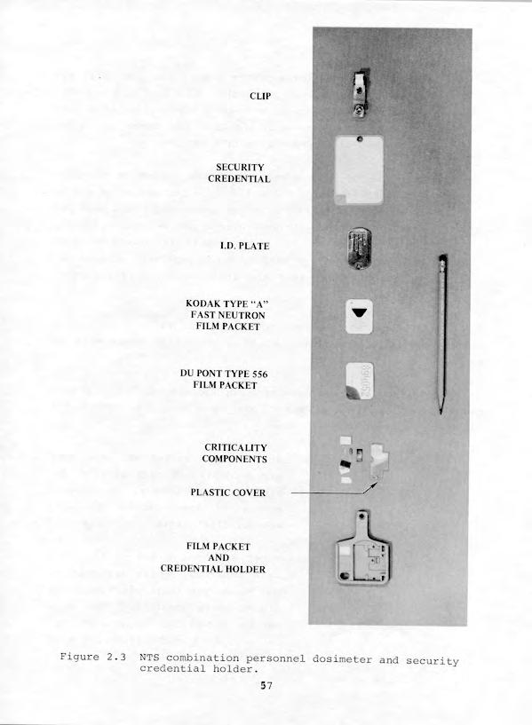
60 D. Monitoring of Personnel Exoosures The Du Pont type film packet was replaced with the NTS combination personnel dosimeter and security credential holder in 1966 to provide increased personnel dosimetry capability necessary to meet the radiation exposure problems associated with nuclear rocket testing and underground nuclear detonations. The holder, designed to accommodate a Du Pont type 556 film packet, a fast neutron packet, an identification plate, criticality accident components, the security credential, and a snaptype clip, had capabilities for determining beta, gamma, X-ray, thermal neutron, fast neutron, high range gamma, and high range neutron doses. Components for criticality accidents (unintentional or accidental nuclear fissioning of device critical materials) included materials which could detect and measure neutron and gamma radiation exposures above the ranges of the film packets. The Du Pont 556 film packet contained two component films, type 519 (low range) and type 834 (high range). Gamma exposure ranges of the two components were 30 mr to 10 R and 10 R to 800 R, respectively. The NTS combination personnel dosimeter and security credential holder is shown in Figure 2.3. Film badges were exchanged routinely each month for all individuals, and upon exit from a radex area when it was suspected that an individual had received 100 mr or more of exposure. Personnel entering radex areas also were issued selfreading pocket dosimeters which indicated accumulated exposure. Upon exit, pocket dosimeter readings were entered on Area Access Registers and added to the yearly and quarterly accumulated exposures from the automated 56
61
62 daily NTS radiation exposure report for use until results of film packet processing were included. Pocket dosimeter readings were only estimates because such readings were less accurate than the doses of record determined after processing film packets. This use of Area Access Registers helped to maintain personnel exposures below the whole-body exposure guides in Chapter 0524: 3000 mrem per quarter and 5000 mrem per year. Personnel with exposures from the report plus any dosimeter reading since the report in excess of 2500 mrem per quarter or 4500 mrem per year were advised not to enter radex areas and their supervisory personnel were so notified Additional methods used for control of radex areas and to prevent spread of contamination to uncontrolled areas were as follows: A daily log book was maintained by Radsafe monitors for each radex area location. These logs were used to record the following information: A. Work accomplished: Where people worked and what work was accomplished were briefly described. Any unusual conditions, such as equipment failure and operational difficulties, were listed. B. Visitors: First and last names of visitors were entered. Their destination and reason for their visit were included where possible. Time they entered and exited the area and results of personnel monitoring were recorded. 58
63 C. Unusual occurrences: Any unusual events which occurred during the shift were recorded. ncluded in this entry were accidents, high-volume water seepage, or any other occurrence of an unusual nature. D. Surveys and samples: nformation collected was recorded as follows: Survey type - Routine or Special* Sample type - Routine or Special* *ndicate requester's name for Special type. E. Date and signature: The date and shift were entered at the beginning of the work period and the log book was signed before leaving the shift. Personnel leaving radex areas removed anticontamination clothing and equipment and placed them in special containers for later laundering or disposal at the designated NTS burial site. Personnel then were monitored to assure radiation levels were below those listed in Part of Appendix D, AEC NTSO-SOP Chapter 0524, Radiological Safety. Personnel decontamination was accomplished if radiation levels were above specified limits. Decontamination usually was accomplished by vacuuming, removing radioactive particles with masking tape patches, washing hands or localized skin areas with soap and water, or showering with soap and water. Vehicles and equipment removed from radex areas were monitored to assure that they met acceptable radiation levels for release on the NTS. Limits for release of vehicles and equipment off the NTS were 0.3 mrad/h beta plus gamma radiation at contact and no detectable alpha acti vity. Vehicles and equipment normally 59
64 were decontaminated by vacuuming and steam cleaning with water or detergent solutions. 2.8 TELEMETERED MEASUREMENTS OF RADATON LEVELS Beginning in the early 1960's, various applications of radiation measurement telemetry were developed at the NTS to determine radiation levels at critical underground and surface areas following nuclear detonations. Multi-detector systems with range capabilities from 0.5 mr/h to 500 R/h and from 10 mr/h to 10,000 R/h, continuously monitored locations of concern after being emplaced and calibrated prior to each test event. on chamber detectors were hard-wire-linked by telephone trunk lines to exposure rate meters at a central console in CP-2. Detector locations were as far as thirty-five miles from this console. These remote radiation monitoring systems provided data for reentry personnel participating in radiation surveys and recovery operations after a nuclear device detonation. The systems aided in substantially reducing radiation exposure of personnel involved in reentry programs, and were useful in detecting any venting or leaking of radioactive effluent to the atmosphere from an underground detonation Telemetry Systems in Use The radiation telemetry systems developed and used had specific applications depending upon distance, terrain, environment, and operational needs. The detection units, systems, and components being studied and developed or in use in 1967 were the following: 60
65 A. Remote Area Monitoring Svstem (RAMS) The principal piece of equipment used to form a RAMS was the RAMP-4. The RAMP-4 was a multi-channel, hardwirelinked, remote area gamma radiation monitoring (telemetry) system, designed and modified by Radsafe and produced by Victoreen nstrument Corporation. t consisted of a probe which used a Neher-White radiation sensing element, hardwire communication to the readout console (up to 35 miles), and components of Victoreen Radector instruments with recorders for readout. The readout covered six logarithmic decades (two threedecade scales) to provide a usual range of 1 mr/h to 1,000 R/h with a relative accuracy of + 15 percent over the temperature range of -loof to 150 F. A permanent array of 21 telemetry stations throughout the NTS as designated by the AEC was maintained and operated continuously. Temporary telemetry arrays for DOD events varied between 20 and 50 stations depending upon the area or tunnel event location. B. Diqital Data System The Digital Data System was a multi-channel, radiolinked, remote gamma radiation monitoring system. The detection unit and communications consisted of a RAMP-4 probe hardwire-linked to a field trailer where signal data was digitized and transmitted via UHF to a trailer at the CP. The readout consisted of a typewriter, a punched tape, and a digital printer, and all three operated simultaneously to provide current operational data, permanent records, and the capability for reproduction of data at any future time. 61
66 This system was used primarily in remote areas where hardwire communication did not exist. Communications between the field trailer and the CP were accomplished via NTS radio net 3 and a UHF net assigned prior to each event for use during installation and checkout, in addition to use during and after the event. C. Well Loqqinq Unit This unit was a Jordan ion chamber gamma detector with a glass-head thermister capable of obtaining gamma radiation or temperature measurements either separately or simultaneously, and was used at drill sites for postevent hole radiation and temperature measurements. Radiation detection ranges were from 0.5 mr/h to 500 R/h and temperature measurement ranges were from OOF to 350 F Remote Area Radiation Detection Monitoring Support Approximately two hundred remote radiation detector channels were available to continuously monitor radiological conditions and assess exposure rates before the test area was entered after detonation. Approximately 20 detector units were positioned in the test area before a shaft-type event. Detectors were placed in circular arrays at appropriate distances from SGZ which varied with device yield and predicted wind direction (see Figures 2.4 and 2.5). Variable numbers of detectors were used aboveground and underground during tunnel-type events. An additional 20 to 35 permanently established remote radiation detector stations operated continuously at living areas, work areas, and other locations throughout NTS (Figure 2.6). The large number of remaining channels was available for additional detector locations and substitute channels. Event-related telemetry detectors operated from zero time until it was determined that release of 62
67 Figure 2.4 Typical remote radiation detection monitoring system for shaft type emplacement site. 63
68 PROBE PLACED ON RM OF MESAABOVEBTUNNEL PORTAL / 1 i G-TUNNEL (U12G) \ \ ~0,000 FT. / \ \ A REMOTE RADATON DETECTOR Figure 2.5 Typical remote radiation detection monitoring system for tunnel-type emplacement site. 64
69 0 PE RMANENT TELEMETRY STATONS Figure 2.6 Typical permanently es tablished remote radiation detector stations operated continuously throughout the NTS. 65
70 radioactivity probably would not occur, or until any released radioactivity had decayed to near-background levels at the telemetry stations. For some events, readout locations were positioned near the FCP or at locations where telephone lines were available, in addition to those events where readouts were located at CP-2. Radiation telemetry data were supplemented with information collected by a mobile air sampling program. Model 102 air sampling units were used to obtain samples of any radioactive effluent released at event time or during the postevent drilling operations. Test groups used an average of 21 units during each test event. Prior to each nuclear detonation experiment, these samplers were placed at specified locations around the test area and units remained in position until drillback operations were completed or the Test Group Director authorized removal of the units. 2.9 AR SUPPORT REQUREMENTS The AFSWC provided direct support to NTSO for DOD underground tests, and other Air Force organizations provided support under AFSWC control as described in section of this report. However, less air support was required as the probability of venting radioactive effluent to the atmosphere decreased with development of more effective containment techniques Changes in Air Support Requirements After 1962, Air Force cloud sampling and cloud tracking aircraft generally were not required, except for AEC cratering events where radioactive effluent clouds were anticipated. Passage of the radioactive effluent through variable amounts and temperatures of rock and other media selectively retained some radi- 66
71 onuclides underground, and changed known ratios of fission prod- ucts previously used during analysis of atmospheric detonation cloud samples. The value of analyzing particulate and gaseous cloud samples to determine characteristics of a detonation decreased. The first change in cloud sampling and tracking support was to a lighter Air Force aircraft, the U-3A, with an Air Force pilot and PHS monitor. The PHS monitor also performed aerial monitoring of selected locations near surface ground zero and along the path of any effluent cloud. This air support later was performed by PHS and contractor personnel in their own aircraft. Perimeter sweeps continued to be conducted daily by Air Force and Security personnel, during reasonable flying weather, to assure that unauthorized vehicles were not entering the NTS over rough terrain or around security barricades on secondary roads. L-20 aircraft used prior to 1968 were replaced with helicopters and other aircraft thereafter. Air security sweeps of the immediate test area were conducted for a few hours before each detonation to assist in clearing the test area and to assure that unauthorized vehicles were not approaching it from directions not controlled by manned security stations. Air support for photography missions during test events and initial radiation surveys after each event did not change. Helicopters with Air Force pilots generally were used with contractor photographers and Radsafe monitors. 2i9.2 Radsafe Support for ndian Springs Air Force Auxiliary Field (SAFAF) Radsafe support facilities had been established about 20 miles southeast of Mercury at SAFAF during atmospheric nuclear device testing series. During 1962 tests, and subsequent DOD 67
72 underground tests requiring support aircraft staged from SAFB (which became SAFAF in 19681, REECo provided all radsafe support functions available at the NTS. This included monitors stationed at the SAFAF radsafe quonset facility and a complete stock of film dosimeters (badges), radiation detection instruments, and anticontamination clothing and equipment for use by aircrews and ground crews. Radsafe monitors issued and exchanged film dosimeters (badges), issued self-reading pocket dosimeters, provided anticontamination clothing and respiratory protection equipment, monitored aircraft and personnel after events, decontaminated personnel, and assisted ground crew personnel with decontamination of aircraft. Figures 2.7 through 2.9 show decontamination and monitoring of typical B-57 cloud sampling aircraft used from 1962 until the type of sampling aircraft was changed. Aircrews departing from contaminated aircraft removed anticontamination clothing and equipment at the radsafe facility, showered, and were monitored to assure complete decontamination before they dressed in regulation clothing and were released. Ground crew personnel who removed particulate and gaseous cloud sample collection media from aircraft or who participated in aircraft decontamination were subject to the same personnel decontamination procedures Radsafe Support for Helicopters Although SAFAF radsafe support extended to all participating aircraft, special helicopter radsafe procedures were implemented because these aircraft landed at NTS and staged from helicopter pads located east of Mercury Highway at the CP area and near a Test Director's FCP established for a particular under- 68
73

74
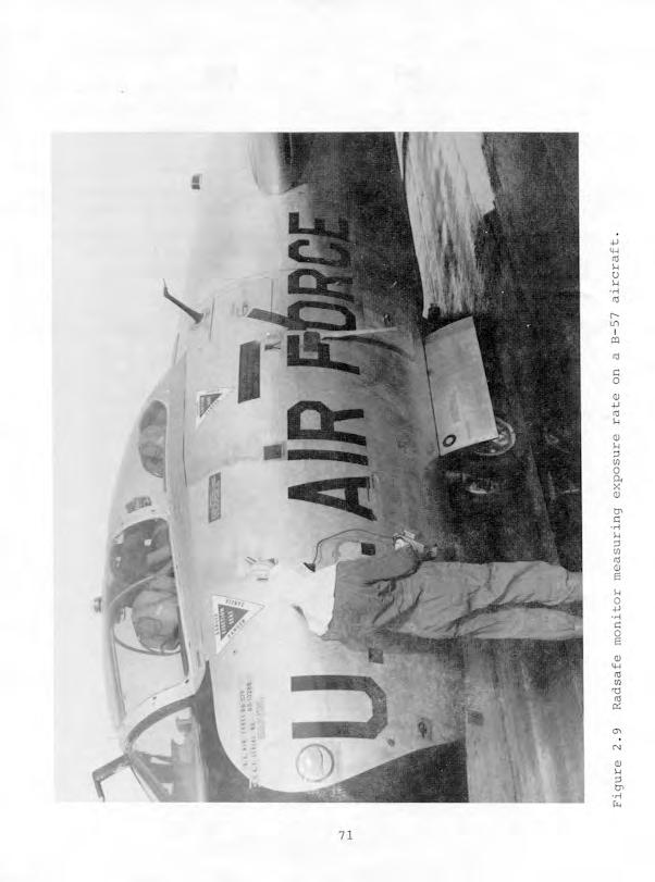
75
76 ground event. Helicopter pilots usually landed at these loca- tions, and were briefed at the CP or particular FCP regarding their scheduled missions or other operational missions. f the mission involved possible contamination of the aircraft, Radsafe monitors lined the floor of the aircraft with plastic, or kraft paper, and masking tape to facilitate decontamination. Pilots and crew members were dressed in anticontamination clothing and provided with film badges, pocket dosimeters, and respiratory protection equipment if airborne radioactive material was anticipated and oxygen masks were not worn. Upon completion of missions, helicopters returned to the landing pads where they were decontaminated by Radsafe monitors. Pilots and crew members were decontaminated at an adjacent forward Radsafe base station, or at CP-2, where the pocket dosimeters were collected and read, and film badges were exchanged if exposures of 100 mr or more were indicated by pocket dosimeters. 72
77 CHAPTER 3 DOOR MST EVENT 3.1 EVENT SUMMARY DOOR MST was a DOD-sponsored underground test detonated at 0930 hours Pacific Daylight Time (PDT) on 31 August 1967 with a yield less than 20 kt. The device was detonated in tunnel U12g.07 at a vertical depth of 1,463 feet and approximately 5,655 feet in from the portal (Figure 3.1). The objective of this test was to determine the response of materials and equipment to a nuclear detonation environment. Government agencies and contractors conducted 11 projects to obtain the desired weapons effects information. Stemming and containment failures occurred and resulted in damage to, and contamination of, the experiments. Effluent was released to the atmosphere, and minor levels of radioactive effluent were detected offsite. 3.2 PREEVENT ACTVTES Responsibilities Safe conduct of all DOOR MST project activities in Area 12 was the responsibility of the DOD Test Group Director. Responsibilities of AEC and AEC contractor personnel were in accordance with established AEC/DOD agreements or were the subject of separate action between Test Command, DASA, and the AEC Nevada Operations Office. Project agencies were responsible for designing, preparing, 73
78 DooR Y ST,~EMMN. ZERO PONT12g.07 (S f 62) AREAS uizg.07 DRFT ( ) 5170 PL CABLE HOLE ASTER CONSOLE ALCOVE u12g.os DRFT AS SEAL DOOR SCALE: 1 NCH = 800 FEET Ul2g TUNNEL PORTAL Figure 3.1 DOOR MST event - tunnel layout.
79 and installing their experiments, or delivering them to the installation contractor. After the event, these agencies were responsible for removing samples, analyzing instrument and sample data, and preparing project reports on experiment results. Because LASL fielded the device, the LASL Test Group Director was responsible for radiological safety within a 6,000-foot radius of ground zero (GZ). This responsibility was in effect from device emplacement until the device was detonated. At that time, the Test Manager relieved the LASL Test Group Director of responsibility and delegated responsibility to the DOD Test Group Director. Device safety and security procedures in the GZ area and the timing and firing control room were in accordance with AEC Manual Chapter 0560, "Program to Prevent Accidental or Unauthorized Nuclear Explosive Detonations." Planning and Preparations A. Tunnel Facilities Construction The DOOR MST experimental facility was installed as designed. t consisted of an 800-foot-long vacuum pipe with two test chambers. Test chamber No. 1 was installed at the end of the pipe 800 feet from the device, while test chamber No. 2 was located 565 feet from the device. B. Radiological Safety Support Procedures for radiation exposure and contamination control during this event were in accordance with requirements of responsible DOD and SC representatives. Radsafe provided monitoring and equipment support, air sampling, and telemetry. Detailed radiological safety reentry plans were given to 75
80 participating agencies prior to the test event. Reference markers and air sampling equipment were positioned in the test area. Radsafe monitors were briefed regarding surface reentry, manned stations, and security station requirements. All RAMS units and air sampling units were installed a minimum of five days prior to scheduled device detonation. Radsafe monitoring teams and supervisory personnel were provided to perform initial surface radiation surveys, perform aerial surveys by helicopter, and participate in reentry parties, as needed. Radsafe personnel also were standing by at the FCP prior to detonation to perform surveys and provide emergency support as directed; provide and issue anticontamination equipment and material, portable instruments, and dosimeters; operate area control check stations; and perform personnel, equipment, and vehicle decontamination, as required. Available anticontamination materials and equipment included head covers, coveralls, shoe covers, full-face masks, supplied-air breathing apparatus, plastic suits, plastic bags, gloves, and masking tape. C. Telemetry and Air Sampling Support Thirty-seven remote telemetry radiation monitoring sys- tem units provided aboveground and underground coverage for the DOOR MST event as shown in Table 3.1. Eleven air sampling units were located as shown in Table
81 Table 3.1. DOOR MST event RATEi unit locations. Station Location (distances are from portal) ABOVEGROUND 1 38 feet at 311"23' azimuth feet at 160'45' azimuth feet at 160"45' azimuth feet at 31"23' azimuth feet at 71"34' azimuth feet at 123"30' azimuth feet at 163'07' azimuth a 223 feet at 245'55' azimuth feet at 334'00' azimuth 10 1,374 feet at 14"56' azimuth 11 1,565 feet at 50"40' azimuth 12 1,445 feet at 81 40' azimuth 13 1,446 feet at 113"30' azimuth 14 1,235 feet at 195"Ol' azimuth 15 1,778 feet at 253"15' azimuth 16 2,687 feet at 28S"O08 azimuth 17 2,048 feet at 330"32' azimuth ia 3,779 feet at 264O41' azimuth 19 4,470 feet at 279O59' azimuth 20 4,795 feet at 293'01' azimuth 21 4,635 feet at 300'44' azimuth 22 4,732 feet at 3Ol"OS' azimuth 23 4,672 feet at 301"35' azimuth 24 4,611 feet at 302"06' azimuth 25 4,709 feet at 302'22' azimuth 26 5,811 feet at 304"29' azimuth 26a 5,378 feet at 308O31' azimuth UNDERGROUND 27 5,098 feet in the 07 drift 28 4,888 feet in the 07 drift 29 4,458 feet in the 07 drift 30 4,358 feet in the 07 drift 31 3,800 feet in the reentry drift 32 2,500 feet in the main drift 33 2,400 feet in the main drift 34 1,200 feet in the main drift feet in the i,.ain drift 36 4,676 feet in t!e 08 drift 77
82 Table 3.2. Air sampling unit locations. Station Number Distance and Azimuth from Portal 1 50 feet at 111" feet at 31"23' feet at 74O13' feet at 123'30' feet at 163'7' feet at 160'45' feet at 304"30' 8 4,635 feet at 300"44' 9 4,732 feet at 301"5' 10 4,611 feet at 302'6' 11 4,709 feet at 302'22' D. Security Coverage Device security procedures in the zero point area and the timing and firing control room were in accordance with AEC Manual Chapter 0560, "Program to Prevent Accidental or Unauthorized Nuclear Explosive Detonations." All personnel entering or exiting the controlled test area were required to stop at muster or control stations for issue of stay-in badges, and issue or return of muster badges. After area control was established, all through traffic was diverted around the controlled area by use of screening stations. n accordance with the "Test Manager's Schedule of Events," contractors and agencies were to have all personnel not connected with this event out of the closed area before the final security sweep began. E. Air Support Event photo documentation was performed by Army Pictori- 78
83 al Service (APS) personnel in a USAF UH-1F aircraft. An additional USAF UH-1F and crew provided dual support coverage by performing aerial security sweeps prior to the event and then being put on emergency standby for the Test Manager's use if needed. Cloud sampling was provided by PHS personnel in a Turbo-Beechcraft with an additional Turbo-Beechcraft on standby at McCarran Airport in Las Vegas. A USAF U-3A aircraft with USAF crew and PHS technical personnel, the EG&G/Nevada Aerial Tracking System (NATS) aircraft, and the EG&G/Aerial Remote Monitoring System (ARMS) aircraft were used for cloud tracking Late Preevent Activities Because this event was originally scheduled for 30 August. 1967, the first security sweep was conducted between 1905 and 2230 hours on 29 August. Shortly after this sweep was completed, early in the morning hours of 30 August, personnel from SC, Stanford Research nstitute (SR), EG&G, LASL, and DOD made final instrumentation checks at the portal, in the tunnel, and at the Rainier Mesa trailer park. They loaded film and checked closed circuit television cameras. A security sweep was conducted between 0100 and 0149 hours on 30 August. Permission to arm the device was granted at 0740 hours and arming was complete by 0840 hours. However, at 0852, zero time was rescheduled for 0930 hours because a storm between Mercury and Las Vegas was causing problems with power lines. At 0925 hours, the decision was made to postpone the test for 24 hours, and a readiness briefing was scheduled for 1500 hours on 30 August. The arming party was given permission to disarm the device at 0930 hours, and completed this task by 1012 hours. August. A security sweep was conducted from 1930 to 2100 hours on 30 79
84 3.3 EVENT-DAY AND CONTNUNG ACTVTES The final security sweep began at 0030 hours on 31 August 1967, and was completed at 0115 hours. All projects were rechecked to assure that instruments were functioning properly. The arming party entered the area at 0610 hours. Permission to arm the device was granted at 0737 hours, arming procedures were completed, and the arming party was clear of the area by 0815 hours. DOOR MST zero time was 0930 hours PDT on 31 August Telemetry and Radioactive Effluent Release Situations At approximately 0945 hours an uncontrolled release began through instrumentation cables. The first telemetry reading outside the underground complex was 0.5 mr/h at 0945 hours at the surface cable hole, which increased to a maximum of 30 R/h at 1105 hours, and then decreased to 3 R/h by 1530 hours. This release consisted primarily of noble gases. A second uncontrolled release, this time from the tunnel portal, started at 1045 hours when a reading of 0.1 mr/h was recorded. This reading increased gradually until a maximum of 40 R/h was reached at 1217 hours. This release consisted of noble gases and radioisotopes of iodine and ruthenium. At 1300 hours, a controlled release took place when tunnel ventilation was turned on and effluent was passed through a filter system. This controlled release situation continued until 1500 hours. Shortly after 1530 hours, a third uncontrolled release occurred from the tunnel portal. t, too, consisted of noble 80
85 gases, iodines, and radioisotopes of ruthenium. At 1730 hours, the tunnel ventilation system again was turned on and effluent was released through the filter system until H+72 hours. Radiation readings continued to decrease steadily thereafter nitial Radiation Survey and Reentry Activities The initial radiation survey of Rainier Mesa trailer park was performed from 1036 hours to 1117 hours on D-day. When radiation readings reached 15 mrad/h and 9 mr/h at Stake 12R-6 (1110 hours) about 2 miles southwest of the portal, the reentry team members put on respiratory protection equipment and completed the survey. Film, magnetic tape, and instrument recovery from Rainier Mesa trailer park was conducted between 1130 and 1220 hours. The reentry teams were dressed in anticontamination clothing and had appropriate respiratory protection equipment available if needed. The maximum exposure rate detected was 500 mr/h at the trailer park approximately 500 feet south from the downhole cables at 1150 hours. A second radiation survey team accompanied the recovery party. Venting prohibited immediate tunnel reentry. Therefore, the initial survey of U12g access roads and tunnel was postponed un- til 1 September Cloud Tracking and Sampling A. PHS Aircraft Mission A USAF U-3A aircraft flown by a USAF pilot with two PHS monitors on board tracked the effluent. Winds on D-day were light and variable, moving the radioactive effluent slowly to the north-northwest. By the time the cloud 81
86 had moved to offsite populated areas, it was diffused over a large area and most of the short-lived radio- nuclides were not detectable. 0. ARMS Aircraft Mission At 1450 hours, a request was made for the ARMS aircraft to perform a cloud tracking and sampling mission. The aircraft departed Las Vegas at 1506 hours and intercepted the effluent cloud over Kawich Valley at 1600 hours. Perimeter tracking was successful, resulting in two complete circumnavigations of the cloud. The maximum count rate was greater than 100,000 cps at 10,000 feet MSL over the portal. The mission was terminated at 1940 hours. C. NATS Cloud Tracking Mission No. 1 The NATS aircraft departed Las Vegas, Nevada, at 0610 hours on 1 September nitial contact with the cloud occurred at 0715 over Railroad Valley. Spotty and intermittent count rates prevented complete circumnavigation and good cloud edge delineations. Upon mission completion at 1130 hours, the aircraft landed at Reno, Nevada. D. NATS Cloud Tracking Mission No. 2 The NATS aircraft departed Reno, Nevada, at 1302 hours on 1 September nitial contact with the cloud was made at 1350 hours over Austin, Nevada. ntensity levels were weak and occasionally intermittent: however, count rates greater than 100,000 cps were detected at 9,500 feet MSL over the DOOR MST portal. The aircraft landed at Las Vegas at 1730 hours after completing its mission. 82
87 3.4 POSTEVENT ACTVTES Portal Survey The initial survey of the U12g access roads and portal area was conducted from 1040 to 1300 hours on 1 September The maximum reading at the portal was 1000 mr/h. After this survey, no further attempts were made to reenter U12g.07 until 5 September. The ventilation system to the 07 drift was not working; however, ventilation was remotely activated to the 08 drift. The 08 drift was a mined but unused drift past the 07 drift entrance in the U12g tunnel complex. Ventilation through the tunnel to the 08 drift would allow access to the 07 drift entrance Tunnel Reentry On 5 September at 1655 hours, a team dressed out in appropriate anticontamination clothing and respiratory protection equipment entered the tunnel to the gas seal door. No tunnel damage was noted to this point. This team then began opening the manway door in the gas seal door, with successful completion of the task occurring at 1802 hours. When the door was opened, team members observed water approximately one foot deep extending 75 to 100 feet beyond the door to the curve in the main drift. A maximum radiation intensity of 10 R/h was detected at the gas seal door. After obtaining radiation measurements, and checking for toxic gases and explosive mixtures, the team exited the tunnel at 1812 hours. On 6 September at 1015 hours, a team (appropriately dressed for entry into a radex area) entered the tunnel to remove bolts from the gas seal door and set up a pump to remove water from the area. They exited the tunnel at 1037 hours. Some problems with 83
88 a ventilation fan occurred later in the day, but an auxiliary fan was started in order to maintain continuity. The primary ventilation fan was back in operation on 8 September. No tunnel entries were allowed on 9 and 10 September. A reentry party attempted to reach the overburden plug on 12 September. They were dressed in anticontamination clothing and provided with respiratory protection equipment as on previous reentries. They entered the tunnel at 1405 hours and proceeded toward the overburden plug, measuring radiation intensities, toxic gases, and explosive mixtures as they traveled. Approximately 550 feet into the 07 drift, they obtained a radiation reading of 20 R/h. The party immediately withdrew from the area and exited the tunnel at 1435 hours. No further reentries were made until 19 September when a reentry team walked out the 08 drift, which was found to be in good condition. On 20 September at 1030 hours, team members dressed in full anticontamination clothing and wearing McCaa-supplied air breathing apparatus proceeded toward the overburden plug. Approximately five feet before reaching the plug, their radiation detection instruments measured 12 R/h. The floor of the 07 drift had become crusty and very soft. Considerable steam was present and bubbles were coming from the manway door. The team exited the tunnel at 1130 hours without proceeding further into the drift. Between 20 September and 3 October, various work parties performed tasks necessary to open the overburden plug door. These reentry operations were generally for extremely short periods of time. The manway door was opened at 0930 hours on 3 October. At that time, a contact reading of 6 R/h was measured at the door, as well as a personnel exposure rate of 1.5 R/h, 500 ppm carbon dioxide, and 200 ppm carbon monoxide. No explosive mixtures were detected. 84
89 The first reentry beyond the overburden plug began at 1025 hours on 5 October. Upon exiting the tunnel at 1110 hours, the team reported the following conditions as recorded in the "Field Support Report:" 1. Radiation intensity was approximately 5 R/h at the over- burden plug manway door. 2. There were eight inches of water on the tunnel floor. 3. Fifty feet beyond the plug, the radiation intensity was 3 R/h and carbon monoxide was 1200 ppm. 4. Debris was estimated to be four feet deep across the tunnel floor. 5. All the lagging was burned out beyond the overburden plug. 6. The temperature was in excess of 130'F. The reentry team aborted the reentry mission because of the condition of the tunnel. At this time, all reentry and experiment recovery operations became concentrated on mining through from the U12e.04 drift Postevent Mining (U12e.04 Drift to U12g.07 Drift) Numerous reentries made into the G tunnel complex after the DOOR MST event indicated that the tunnel was extensively damaged on the zero point side of the overburden plug. No lagging remained between the sets, rubble and spalled rock were on the tunnel floor, and high temperatures were encountered. Explosive mixtures, toxic gases, and hi;jh radiation fields were encountered as well. Even after partial ventilation of the tunnel, it was 85
90 determined that the presence of debris and existence of sub- stantial radiation levels precluded experiment recovery through the g.07 drift. n order to effect experiment recovery, the decision was made to mine a reentry tunnel from the existing U12e.04 personnel drift to the U12g.07 drift (Figure 3.2). Rehabilitation of the e.04 drift was conducted between 15 and 27 September, with mining toward U12g.07 beginning on 28 September. This recovery drift intersected the DOOR MST drift at the Tunnel and Pipe Seal (TAPS) No. 1. Two branch drifts, the containment assessment drift and the experiment recovery drift, were mined paralleling the DOOR MST drift. Crosscut drifts were mined at appropriate stations of interest (Figure 3.3). On 1 November 1967, the concrete plug surrounding TAPS No. 1 became visible in the working face. Contact readings at this location were 1 R/h with a personnel exposure rate of 25 mr/h. After the round was mucked out, the exposure rate increased to 50 mr/h at the face. During graveyard shift on 3 November, the reentry heading broke into the 9.07 drift on the portal side of the TAPS No. 1 plug. Considerable steam was observed coming from the g.07 drift, and work in the heading was stopped until a procedure could be developed for continuing. A survey of the muckpile indicated an exposure rate of mr/h and a temperature of 130 F. After the round was mucked out on 6 November, the exposure rate in the 9.07 drift was found to be 4 R/h. Crosscut No. 2, mined from the containment assessment drift to the zero point side of TAPS No. 2, broke into the g.07 LOS drift on 8 November. Contaminated water was noted seeping through the muck pile into the containment assessment drift. A nauseat- ing odor also was noted, but could not be identified. Work was 86

91
OPERATIONS NOUGAT AND WHETSTONE
 MHOLD 1. BRODE DNA 632OF OPERATIONS NOUGAT AND WHETSTONE EVENTS HARD HAT, DANNY BOY, MARSHMALLOW, MUDPACK, WISHBONE, GUMDROP, DILUTED WATERS, AND TINY TOT 15 February 1962-17 June 1965 United States Underground
Operation DOMINIC II
 Operation DOMINIC II Note: For information related to claims, call the Department of Veterans Affairs (VA) at 800-827-1000 or the Department of Justice (DOJ) at 800-729-7327. For all other information,
Operation BUSTER-JANGLE
 Operation BUSTER-JANGLE Note: For information related to claims, call the Department of Veterans Affairs (VA) at 800-827-1000 or the Department of Justice (DOJ) at 800-729-7327. For all other information,
Operation HARDTACK II
 Operation HARDTACK II Note: For information related to claims, call the Department of Veterans Affairs (VA) at 800-827-1000 or the Department of Justice (DOJ) at 800-729-7327. For all other information,
Operation TUMBLER-SNAPPER
 Operation TUMBLER-SNAPPER Note: For information related to claims, call the Department of Veterans Affairs (VA) at 800-827-1000 or the Department of Justice (DOJ) at 800-729-7327. For all other information,
Operation PLUMBBOB. Historical Background
 Operation PLUMBBOB Note: For information related to claims, call the Department of Veterans Affairs (VA) at 800-827-1000 or the Department of Justice (DOJ) at 800-729-7327. For all other information, call
Projects GNOME and SEDAN The PLOWSHARE Program
 Projects GNOME and SEDAN The PLOWSHARE Program Note: For information related to claims, call the Department of Veterans Affairs (VA) at 800-827-1000 or the Department of Justice (DOJ) at 800-729-7327.
Operation UPSHOT-KNOTHOLE
 Operation UPSHOT-KNOTHOLE Note: For information related to claims, call the Department of Veterans Affairs (VA) at 800-827-1000 or the Department of Justice (DOJ) at 800-729-7327. For all other information,
OPERATION TUMBLER-SNAPPER 1952
 , DNA 6019F OPERATION TUMBLER-SNAPPER 1952 United States Atmospheric Nuclear Weapons Tests Nuclear Test Personnel Review Prepared by the Defense Nuclear Agency as Executive Agency for the Department of
OPERATION BUSTER-JANGLE 1951
 DNA 6023F OPERATION BUSTER-JANGLE 1951 United States Atmospheric Nuclear Weapons Tests Nuclear Test Personnel Review Prepared by the Defense Nuclear Agency as Executive Agency for the Department of Defense
SHOTS ABLE, BAKER, CHARLIE, AND DOG. TUMBLER-SNAPPER Series 1 APRIL - 1 MAY 1952
 DNA 6020F SHOTS ABLE, BAKER, CHARLIE, AND DOG The First Tests of the TUMBLER-SNAPPER Series 1 APRIL - 1 MAY 1952 United States Atmospheric Nuclear Weapons Testa Nuclear Test Personnel Review Prepared by
OPERATION DOMINIC3I. Shots LITTLE FELLER I[, JOHNIE BOY, SMALL BOY, LITTLE FELLER I 7 JULY-17 JULY 1962
 DNA 6027F OPERATION DOMINIC3I Shots LITTLE FELLER I[, JOHNIE BOY, SMALL BOY, LITTLE FELLER I 7 JULY-17 JULY 1962 " MAY 1 9 18._ I,s A % STATESOt - United States Atmospheric Nuclear Weapons Tests >" Nuclear
EIhIIIIIIIIu. EIIIIIIIIIIIIu
 AD-Ai22 243 SHOTS SUGAR AND UNCLE THE FINAL TESTS OF THE1/ EIhIIIIIIIIu BUSTER-JANGLE SERIES 19 NOVE..(U) JRB ASSOCIATES INC MCLEAN VR J PONTON ET AL. 23 JUN 82 DNA-6825F UNCLASSIFIED DNAeSi-79-C-8473
Destroy this report when it is no longer needed. Do not return to sender.
 Destroy this report when it is no longer needed. Do not return to sender. PLEASE NOTIFY THE DEFENSE NUCLEAR AGENCY, ATTN: STTI, WASHINGTON, D.C. 20305, IF YOUR ADDRESS IS INCORRECT, IF YOU WISH TO BE DELETED
SHOTS. WHEELER TO MORGAN The Final Eight Tests of the PLUMBBOB Series 6 SEPTEMBER - 7 OCTOBER 1957
 DNA 6007F SHOTS WHEELER TO MORGAN The Final Eight Tests of the PLUMBBOB Series 6 SEPTEMBER - 7 OCTOBER 1957 United States Atmospheric Nuclear Weapons Tests Nuclear Test Personnel Review llili bookbelongs
BUSTER-JANGLE OPERATION. 4- Prepared by the Defense Nuclear Agency as Executive Agency DNA 6023F
 DNA 6023F OPERATION BUSTER-JANGLE 1951 United States Atmospheric Nuclear Weapons Tests Nuclear Test Personnel Review 4- Prepared by the Defense Nuclear Agency as Executive Agency - for the Department of
Operations Praetorian, Phalanx, Fusileer, and Grenadier
 Defense Nuclear Agency Alexandria, VA 22310-3398 JUL 23 1993 DAAC Operations Praetorian, Phalanx, Fusileer, and Grenadier DNA 6327F Events HURON LANDNG/DAMOND ACE, MN JADE, TOMME/MDNGHT ZEPHYR, MDA MYTH/MLAGRO,
A Test ~:of the r--l > 31 AUGUST Nuclear Test Persannef Review
 DNA 6004F A Test ~:of the r--l > PLU MBBCB., Series 31 AUGUST 1957 United States Atmospheric N,uclear We!apons Tests Nuclear Test Persannef Review Prepared by the Defense Nucle&Agency as Executive Agency,~._
OPERATBON UPSHOT-KNOTHOLE 1953
 DNA 64F OPERATBON UPSHOTKNOTHOLE 953 United States Atmospheric Nuclear Weapons Tests Nuclear Test Personnel Review Prepared by the Defense Nuclear Agency as Executive Agency for the Department of Defense
A Brief Synopsis of Army Contributions to Early Health Physics and Nuclear Engineering
 A Brief Synopsis of Army Contributions to Early Health Physics and Nuclear Engineering Gregory R. Komp, CHP Class of 92 The views presented are those of the speaker and do not necessarily represent the
Guide to the William Geagley Collection on Nuclear Safety
 Guide to the William Geagley Collection on Nuclear Safety This finding aid was created by Lindsay Oden and Sarah Jones on April 27, 2018. Persistent URL for this finding aid: http://n2t.net/ark:/62930/f1n602
Defense Threat Reduction Agency s. Defense Threat Reduction Information Analysis Center
 Defense Threat Reduction Agency s Defense Threat Reduction Information Analysis Center 19 November 2008 Approved for Public Release U.S. Government Work (17 USC 105) Not copyrighted in the U.S. Report
POLICY AND GLOBAL AFFAIRS The National Academies Press Washington, DC March 30, /30/2012 1
 POLICY AND GLOBAL AFFAIRS The National Academies Press Washington, DC www.nap.edu March 30, 2012 3/30/2012 1 The Study Committee ELLEN D. WILLIAMS, Chair, BP MARVIN L. ADAMS, Texas A&M University LINTON
SEC J - Appendix G Modifications to Applicable Directives
 DOE O 110.3A DOE O 130.1 DOE M 140.1-1B DOE O 142.1 DOE M 142.2-1, DOE O 142.2A, DOE O 142.3A Conference Management Budget Formulation Interface with the Defense Nuclear Facilities Safety Board Classified
DEPARTMENT OF THE NAVY OFFICE OF THE CHIEF OF NAVAL OPERATIONS 2000 NAVY PENTAGON WASHINGTON, D,C,
 -= DEPARTMENT OF THE NAVY OFFICE OF THE CHIEF OF NAVAL OPERATIONS 2000 NAVY PENTAGON WASHINGTON, D,C, 20350-2000 IN REPLY REFER TO 5211 Ser DNS-36/6U833273 7 Sep 06 From: Subj: Chief of Naval Operations
SHOTS DIABLO TO FRANKLIN PRIME
 SHOTS DNA 6006F DIABLO TO FRANKLIN PRIME The Mid-Series Tests of the PLUMBBOB Series 15 JULY - 30 AUGUST 1957 United States Atmospheric Nuclear Weapons Tests Nuclear Test Personnel Review Prepared by the
SHOT PRISCILLA A Test of the PLUMBBOB Series 24 JUNE 1957
 DNA 6003F SHOT PRISCILLA A Test of the PLUMBBOB Series 24 JUNE 1957 This is the DASIAC FILE COPY Please DO NOT REMOVE from Reading Area. United States Atmospheric Nuclear Weapons Tests Nuclear Test Personnel
GNOME AND SEDAN The PLOWSHARE POgra
 PROJ ECTSNF GNOME AND SEDAN The PLOWSHARE POgra I' jul 6 1983 United States Atmospheric Nuclear Weapons Tests Nuclear Test Personnel Review CL.dis Thi. -docuament has =ben ppoved for puhu'i reeae iand
STATEMENT OF DR. STEPHEN YOUNGER DIRECTOR, DEFENSE THREAT REDUCTION AGENCY BEFORE THE SENATE ARMED SERVICES COMMITTEE
 FOR OFFICIAL USE ONLY UNTIL RELEASED BY THE SENATE ARMED SERVICES COMMITTEE STATEMENT OF DR. STEPHEN YOUNGER DIRECTOR, DEFENSE THREAT REDUCTION AGENCY BEFORE THE SENATE ARMED SERVICES COMMITTEE EMERGING
F/6 18/3 SHOT SMOKY, A TEST MAY AS1 P 5 HARRIS, C LOWERY, A G NELSON DNAOOI-7A-C-0311 UNCLASSIFIED JAYCOR DNA-6004F NL
 F/6 18/3 SHOT SMOKY, A TEST 7 AA103 828 JAYCOR ALEXANDRIA VA OF THE PLUMBBOR SERIES, 31 AUGUST 1957.(U) MAY AS1 P 5 HARRIS, C LOWERY, A G NELSON DNAOOI-7A-C-0311 UNCLASSIFIED JAYCOR-2087-79-01 DNA-6004F
Public Lands Committee Briefing
 Hawthorne Army Depot Public Lands Committee Briefing LTC John Summers Commander DSN: 830-7001 Email: johnny.summers@us.army.mil Hawthorne Will Always Deliver EXHIBIT C - LANDS Meeting Date: 03-24-06 Document
Radiological Consequence Management
 Radiological Consequence Management David Bowman, Ph.D., CHP Consequence Management Program Manager Office of Emergency Response (NA-42) National Nuclear Security Administration U.S. Department of Energy
CHAPTER 20 SUMMARY OF SPECIALIZED CAPABILITIES
 DoD 51 OO.52-M CHAPTER 20 SUMMARY OF SPECIALIZED CAPABILITIES 20-1 GENERAL Numerous units and organizations with specialized capabilities are discussed throughout this document. This chapter summarizes
COMPLIANCE WITH THIS PUBLICATION IS MANDATORY
 BY ORDER OF THE SECRETARY OF THE AIR FORCE AIR FORCE INSTRUCTION 91-110 13 JANUARY 2015 Safety NUCLEAR SAFETY REVIEW AND LAUNCH APPROVAL FOR SPACE OR MISSILE USE OF RADIOACTIVE MATERIAL AND NUCLEAR SYSTEMS
Joint Electronics Type Designation Automated System
 Army Regulation 70 76 SECNAVINST 2830.1 AFI 60 105 Research, Development, and Acquisition Joint Electronics Type Designation Automated System Headquarters Departments of the Army, the Navy, and the Air
Department of Defense DIRECTIVE
 Department of Defense DIRECTIVE NUMBER 5105.68 December 19, 2008 DA&M SUBJECT: Pentagon Force Protection Agency (PFPA) References: See Enclosure 1 1. PURPOSE. This Directive, under the authority vested
4677 th DEFENSE SYSTEMS EVALUATION SQUADRON
 4677 th DEFENSE SYSTEMS EVALUATION SQUADRON Evaluation Flight, a Hill AFB tenant organization. 18 Mar 1954 Air Defense Command redesignated its 4677th Radar Evaluation Squadron as the 4677th Defense Systems
Lawrence Livermore National Lab Perspective
 Lawrence Livermore National Lab Perspective Building a Strong Partnership with DoD and DoD Industry for National Security 41 st Air Armament Symposium, Ft. Walton Beach, Florida November 3, 2015 Lara D.
Quality Assurance Specialist (Ammunition Surveillance)
") Army Regulation 702 12 Product Assurance Quality Assurance Specialist (Ammunition Surveillance) Headquarters Department of the Army Washington, DC 20 March 2002 UNCLASSIFIED Report Documentation Page Report
Army Regulation 702 12 Product Assurance Quality Assurance Specialist (Ammunition Surveillance) Headquarters Department of the Army Washington, DC 20 March 2002 UNCLASSIFIED Report Documentation Page Report
The Army Proponent System
 Army Regulation 5 22 Management The Army Proponent System Headquarters Department of the Army Washington, DC 3 October 1986 UNCLASSIFIED Report Documentation Page Report Date 03 Oct 1986 Report Type N/A
Dr. Mohamed Mughal. Homeland Defense Business Unit U.S. Army Soldier and Biological Chemical Command Department of Defense
 Dr. Mohamed Mughal Homeland Defense Business Unit Department of Defense Telephone: 410-436-4921 Email: mohamed.mughal@sbccom.apgea.army.mil Report Documentation Page Report Date 30Apr2001 Report Type N/A
FIG 18/3. S EP A C MAAG J PoNToN ONAD O1-79-C-0473 UNCLSSIFED ONA-600F N
 FIG 18/3 SHOTS OIAB 0 To AD-AIM 683 J RB ASSOCIATES INC FRANKLIN MCLEAN PRIME, VA THE mro-series TESTS OF THE PLU--ETC(U) S EP A C MAAG J PoNToN ONAD O1-79-C-0473 UNCLSSIFED ONA-600F N 00 - AI UNCLASSIFIED
Training and Evaluation Outline Report
 Training and Evaluation Outline Report Task Number: 01-6-0416 Task Title: Conduct Aviation Missions as part of an Area Defense Supporting Reference(s): Step Number Reference ID Reference Name Required
DoD Countermine and Improvised Explosive Device Defeat Systems Contracts for the Vehicle Optics Sensor System
 Report No. DODIG-2012-005 October 28, 2011 DoD Countermine and Improvised Explosive Device Defeat Systems Contracts for the Vehicle Optics Sensor System Report Documentation Page Form Approved OMB No.
THE VIEWS AND ISSUES OF AMERICA S ATOMIC VETERANS N-001
 THE VIEWS AND ISSUES OF AMERICA S ATOMIC VETERANS N-001 TRINITY SITE - NEW MEXICO THE FIRST ATOMIC BOMB TEST JULY 16, 1945 ATOMIC BOMB DROPPED OVER HIROSHIMA, JAPAN AUGUST 6, 1945 ATOMIC BOMB DROPPED OVER
Office of Intelligence
 Office of Intelligence Executive Budget Summary Mission The Intelligence mission is to provide the Department, other U.S. Government policy makers, and the Intelligence Community with timely, accurate,
Department of Defense INSTRUCTION
 Department of Defense INSTRUCTION NUMBER 6055.8 March 31, 1989 SUBJECT: Occupational Radiation Protection Program Administrative Reissuance Incorporating Change 1, May 6, 1996 USD(A&T) References: (a)
Training and Evaluation Outline Report
 Training and Evaluation Outline Report Task : 71-8-5702 Task Title: Determine Integrated Airspace User Requirements (Brigade-Corps) Distribution Restriction: for public release; distribution is unlimited.
DOD INSTRUCTION DOD LOW-LEVEL RADIOACTIVE WASTE (LLRW) PROGRAM
 PROGRAM") DOD INSTRUCTION 4715.27 DOD LOW-LEVEL RADIOACTIVE WASTE (LLRW) PROGRAM Originating Component: Office of the Under Secretary of Defense for Acquisition, Technology, and Logistics Effective: July 7, 2017
DOD INSTRUCTION 4715.27 DOD LOW-LEVEL RADIOACTIVE WASTE (LLRW) PROGRAM Originating Component: Office of the Under Secretary of Defense for Acquisition, Technology, and Logistics Effective: July 7, 2017
BY ORDER OF THE SECRETARY OF THE AIR FORCE AIR FORCE HEADQUARTERS OPERATING INSTRUCTION APRIL Security
 BY ORDER OF THE SECRETARY OF THE AIR FORCE AIR FORCE HEADQUARTERS OPERATING INSTRUCTION 31-2 1 APRIL 1998 Security POLICY AND PROCEDURES FOR HANDLING AND SAFEGUARDING NORTH ATLANTIC TREATY ORGANIZATION
COMPLIANCE WITH THIS PUBLICATION IS MANDATORY
 BY ORDER OF THE SECRETARY OF THE AIR FORCE AIR FORCE INSTRUCTION 91-104 23 APRIL 2013 Safety NUCLEAR SURETY TAMPER CONTROL AND DETECTION PROGRAMS COMPLIANCE WITH THIS PUBLICATION IS MANDATORY ACCESSIBILITY:
Subj: NUCLEAR SURVIVABILITY POLICY FOR NAVY AND MARINE CORPS SYSTEMS
 DEPARTMENT OF THE NAVY OFFICE OF THE CHIEF OF NAVAL OPERATIONS 2000 NAVY PENTAGON WASHINGTON, DC 20350-2000 OPNAVINST 3401.3B N9 OPNAV INSTRUCTION 3401.3B From: Chief of Naval Operations Subj: NUCLEAR
National Nuclear Security Administration
 National Nuclear Security Administration Presentation to Workshop on Risk Assessment and Safety Decision-Making Under Uncertainly By Jim McConnell, Assistant Deputy Administrator for Nuclear Safety, Nuclear
Department of Defense INSTRUCTION
 Department of Defense INSTRUCTION NUMBER 5230.16 October 6, 2015 ATSD(PA) SUBJECT: Nuclear-Radiological Incident Public Affairs (PA) Guidance References: See Enclosure 1 1. PURPOSE. This instruction reissues
SERIES 1300 DIRECTOR, DEFENSE RESEARCH AND ENGINEERING (DDR&E) DEFENSE RESEARCH AND ENGINEERING (NC )
 DEFENSE RESEARCH AND ENGINEERING (NC )") SERIES 1300 DIRECTOR, DEFENSE RESEARCH AND ENGINEERING (DDR&E) 1300. DEFENSE RESEARCH AND ENGINEERING (NC1-330-77-15) These files relate to research and engineering (R&E) and pertain to: Scientific and
SERIES 1300 DIRECTOR, DEFENSE RESEARCH AND ENGINEERING (DDR&E) 1300. DEFENSE RESEARCH AND ENGINEERING (NC1-330-77-15) These files relate to research and engineering (R&E) and pertain to: Scientific and
Military Radar Applications
 Military Radar Applications The Concept of the Operational Military Radar The need arises during the times of the hostilities on the tactical, operational and strategic levels. General importance defensive
REGULATORY DOCUMENTS. The main classes of regulatory documents developed by the CNSC are:
 Canadian Nuclear Safety Commission Commission canadienne de sûreté nucléaire REGULATORY GUIDE Emergency Planning at Class I Nuclear Facilities and Uranium Mines and Mills G-225 August 2001 REGULATORY DOCUMENTS
STOCKTON POLICE DEPARTMENT GENERAL ORDER DOWNED AIRPLANES SUBJECT
 STOCKTON POLICE DEPARTMENT GENERAL ORDER DOWNED AIRPLANES SUBJECT DATE: March 1, 2005 NO: FROM: CHIEF ERIC JONES TO: ALL PERSONNEL INDEX: Airplane Crashes Procedure for Plane Crashes Landing of Aircraft
Subj: AVIATION-SERIES NAVAL TACTICS, TECHNIQUES AND PROCEDURES MANUALS AND NAVAL AVIATION TECHNICAL INFORMATION PRODUCT PROGRAM
 DEPARTMENT OF THE NAVY OFFCE OF THE CHEF OF NAVAL OPERATONS 2000 NAVY PENTAGON WASHNGTON, D.C. 203502000 N REPLY REFER TO OPNAVNST 3510.15A N88 OPNAV NSTRUCTON 3510.15A From: Chief of Naval Operations
Department of Defense DIRECTIVE
 Department of Defense DIRECTIVE NUMBER 5105.72 April 26, 2016 DCMO SUBJECT: Defense Technology Security Administration (DTSA) References: See Enclosure 1 1. PURPOSE. This directive reissues DoD Directive
Training and Evaluation Outline Report
 Training and Evaluation Outline Report Status: Approved 20 Mar 2015 Effective Date: 15 Sep 2016 Task Number: 71-8-5715 Task Title: Control Tactical Airspace (Brigade - Corps) Distribution Restriction:
Security of Unclassified Army Property (Sensitive and Nonsensitive)
") Army Regulation 190 51 Military Police Security of Unclassified Army Property (Sensitive and Nonsensitive) Headquarters Department of the Army Washington, DC 30 September 1993 UNCLASSIFIED SUMMARY of CHANGE
Army Regulation 190 51 Military Police Security of Unclassified Army Property (Sensitive and Nonsensitive) Headquarters Department of the Army Washington, DC 30 September 1993 UNCLASSIFIED SUMMARY of CHANGE
National Nuclear Security Administration. November 2015
 National Nuclear Security Administration November 2015 NNSA Leadership Lieutenant General Frank Klotz Undersecretary for Nuclear Security and NNSA Administrator Madelyn Creedon Principal Deputy Administrator
Munitions Support for Joint Operations
 Army Regulation 700 100 MCO 8012.1 Logistics Munitions Support for Joint Operations Headquarters Departments of the Army, and the Marines Washington, DC 26 March 2014 UNCLASSIFIED SUMMARY of CHANGE AR
Department of Defense DIRECTIVE
 Department of Defense DIRECTIVE NUMBER 1015.14 July 16, 2003 Certified Current as of November 21, 2003 SUBJECT: Establishment, Management, and Control of Nonappropriated Fund Instrumentalities and Financial
EOD Courses ATOM Training Ltd Courses 2018
 ATOM EOD Courses Catalogue 2018 Published: Jan 2018 Version: V1.1 Publisher: ATOM Training Limited Alford House Epson Square White Horse Business Park Trowbridge Wiltshire BA14 0XG United Kingdom The courses
Department of Defense INSTRUCTION
 Department of Defense INSTRUCTION NUMBER 5230.27 November 18, 2016 Incorporating Change 1, September 15, 2017 USD(AT&L) SUBJECT: Presentation of DoD-Related Scientific and Technical Papers at Meetings
Procedural Guidance for Conducting DoD Classified Conferences
 Procedural Guidance for Conducting DoD Classified Conferences Prepared By July 2008 Security professionals may find this guidance useful when they are involved in hosting/coordinating DoD classified conferences.
April 01, 1986 New Evidence on 1986 US Air Raid on Libya
 Digital Archive International History Declassified digitalarchive.wilsoncenter.org April 01, 1986 New Evidence on 1986 US Air Raid on Libya Citation: New Evidence on 1986 US Air Raid on Libya, April 01,
DANGER WARNING CAUTION
 Training and Evaluation Outline Report Task Number: 01-6-0447 Task Title: Coordinate Intra-Theater Lift Supporting Reference(s): Step Number Reference ID Reference Name Required Primary ATTP 4-0.1 Army
COMPLIANCE WITH THIS PUBLICATION IS MANDATORY
 BY ORDER OF THE COMMANDER MACDILL AIR FORCE BASE MACDILL AIR FORCE BASE INSTRUCTION 48-100 23 JANUARY 2015 Aerospace Medicine INSTALLATION RADIATION SAFETY PROGRAM COMPLIANCE WITH THIS PUBLICATION IS MANDATORY
COMPLIANCE WITH THIS PUBLICATION IS MANDATORY
 BY ORDER OF THE COMMANDER HILL AIR FORCE BASE HILL AIR FORCE BASE INSTRUCTION 21-202 6 APRIL 2017 Maintenance CONSOLIDATED MUNITIONS CONTROL CENTER COMPLIANCE WITH THIS PUBLICATION IS MANDATORY ACCESSIBILITY:
MAINTAINING GLOBAL VIGILANCE
 SU PR A E T ULTR A MAINTAINING GLOBAL The National Reconnaissance Office (NRO) is a joint Department of Defense (DoD)-Intelligence Community (IC) organization responsible for developing, launching, and
Department of Defense DIRECTIVE
 Department of Defense DIRECTIVE NUMBER 5105.68 May 3, 2002 Certified Current as of November 21, 2003 SUBJECT: Pentagon Force Protection Agency DA&M References: (a) Title 10, United States Code (b) DoD
Department of Defense MANUAL
 Department of Defense MANUAL NUMBER 3200.14, Volume 2 January 5, 2015 Incorporating Change 1, November 21, 2017 USD(AT&L) SUBJECT: Principles and Operational Parameters of the DoD Scientific and Technical
Department of Defense DIRECTIVE
 Department of Defense DIRECTIVE NUMBER 1300.22 October 30, 2015 USD(P&R) SUBJECT: Mortuary Affairs Policy References: See Enclosure 1 1. PURPOSE. This directive: a. Reissues DoD Directive (DoDD) 1300.22E
THE CTBT AND ON-SITE INSPECTIONS
 THE CTBT AND ON-SITE INSPECTIONS The Preparatory Commission for the Comprehensive Nuclear-Test-Ban Treaty Organization is mandated to carry out the necessary preparations for the effective implementation
Center for National Response
 Research The Planning, Inc. Center for National Response The West Virginia WMD Memorial Tunnel Project Presented by: CSM (R) Mel Wick Report Documentation Page Report Date 09Jul2001 Report Type N/A Dates
Overview of the History of Nuclear Testing 1945 until today
 Overview of the History of Nuclear Testing 1945 until today Presented at the Vienna Conference on the Humanitarian Impact of Nuclear Weapons 8 and 9 December 2014 in the Hofburg Palace Vienna, Austria
Student Guide: North Atlantic Treaty Organization
 Length Two (2) Hours Description This course provides the student with a basic understanding of NATO information security procedures, access requirements, personnel and facility security requirements,
Joint Task Force. significant. supporting. the event
 Joint Task Force RNC The 2008 Republican National Convention showcased the Minnesota National Guard s capability to support civil authorities. With augmentation from all branches of military service, the
DOE Response to a Nuclear or Radiological Incident. Alan Remick Consequence Management Programs Manager
 DOE Response to a Nuclear or Radiological Incident Alan Remick Consequence Management Programs Manager NA-42 Mission & Authorities Provide a versatile, capable, nuclear or radiological emergency response
DEC CCO 3571.lA 3B. COMBAT CENTER ORDER 3571.lA. From: To: Commanding General Distribution List. Subj: EXPLOSIVE ORDNANCE DISPOSAL
 UNITED STATES MARINE CORPS MARINE AIR GROUND TASK FORCE TRAINING COMMAND MARINE CORPS AIR GROUND COMBAT CENTER BOX 788100 TWENTYNINE PALMS, CALIFORNIA 92278-8100 COMBAT CENTER ORDER 3571.lA CCO 3571.lA
Remote Sensor Operations
 MCRP 2-24B Remote Sensor Operations U.S. Marine Corps PCN 144 000153 00 MCCDC (C 42) 13 Jul 2004 E R R A T U M to MCRP 2-24B REMOTE SENSOR OPERATIONS 1. Change the publication short title to read MCRP
H. R IN THE HOUSE OF REPRESENTATIVES
 I TH CONGRESS 1ST SESSION H. R. To preserve the cooperative, peaceful uses of space for the benefit of all humankind by permanently prohibiting the basing of weapons in space by the United States, and
Yucca Mountain and Interim Storage Proposed Appropriation Language
 Proposed Appropriation Language NUCLEAR WASTE DISPOSAL For Department of Energy expenses necessary for nuclear waste disposal activities to carry out the purposes of the Nuclear Waste Policy Act of 1982,
FM MILITARY POLICE LEADERS HANDBOOK. (Formerly FM 19-4) HEADQUARTERS, DEPARTMENT OF THE ARMY
 HEADQUARTERS, DEPARTMENT OF THE ARMY") (Formerly FM 19-4) MILITARY POLICE LEADERS HANDBOOK HEADQUARTERS, DEPARTMENT OF THE ARMY DISTRIBUTION RESTRICTION: distribution is unlimited. Approved for public release; (FM 19-4) Field Manual No. 3-19.4
(Formerly FM 19-4) MILITARY POLICE LEADERS HANDBOOK HEADQUARTERS, DEPARTMENT OF THE ARMY DISTRIBUTION RESTRICTION: distribution is unlimited. Approved for public release; (FM 19-4) Field Manual No. 3-19.4
The 1969 ACDA Study on Warhead Dismantlement Frank von Hippel
 OCCASIONAL REPORT The 1969 ACDA Study on Warhead Dismantlement Frank von Hippel In response to a Freedom of Information request, the US Arms Control and Disarmament Agency (ACDA) has just unearthed from
Temporary Cross-Border Movement of Land Forces Between the United States and Canada
 Army Regulation 525 16 Military Operations Temporary Cross-Border Movement of Land Forces Between the United States and Canada Headquarters Department of the Army Washington, DC 05 July 1973 UNCLASSIFIED
Nuclear Weapons Data Management
 LA-UR-12-25112 Approved for public release; distribution is unlimited. Title: Nuclear Weapons Data Management Author(s): Garcia, Manuel A. Intended for: Meeting with Federal Managers to discuss current
Training and Evaluation Outline Report
 Training and Evaluation Outline Report Task Number: 12-1-1212 Task Title: Perform Transient Personnel Accountability Distribution Restriction: Approved for public release; distribution is unlimited. Destruction
Department of Defense DIRECTIVE
 Department of Defense DIRECTIVE SUBJECT: Defense Security Service (DSS) References: See Enclosure 1 NUMBER 5105.42 August 3, 2010 Incorporating Change 1, March 31, 2011 DA&M 1. PURPOSE. Pursuant to the
Safety FORT SILL GROUND PRE-ACCIDENT PLAN
 Department of the Army *Fort Sill Regulation 385-4 Headquarters, U.S. Army Garrison 462 Hamilton Road, Suite 120 Fort Sill, Oklahoma 73503 17 December 2015 Safety FORT SILL GROUND PRE-ACCIDENT PLAN Summary.
Commercial Space: Questions Regarding the Legal and Regulatory Environment
 Commercial Space: Questions Regarding the Legal and Regulatory Environment Franceska O. Schroeder Principal, Fish & Richardson P.C. Legal Counsel, American Astronautical Society Washington, D.C. Dupont
Naval Support Facility. Indian Head. Supporting Our Military and Our Nation INSTALLATION OVERVIEW JULY 2010 APPROVED FOR PUBLIC RELEASE
 Naval Support Facility Indian Head Supporting Our Military and Our Nation INSTALLATION OVERVIEW JULY 2010 APPROVED FOR PUBLIC RELEASE Indian Head A Unique Naval Heritage Indian Head Naval Proving Ground
Edited extract from: Department of the Army Historical Summary, FY 1979 (Washington, D.C.: U.S. Army Center of Military History, 1982, pp
 Edited extract from: Department of the Army Historical Summary, FY 1979 (Washington, D.C.: U.S. Army Center of Military History, 1982, pp. 179-186.) Ballistic Missile Defense The Ballistic Missile Defense
OFFICE OF THE INSPECTOR GENERAL FUNCTIONAL AND PHYSICAL CONFIGURATION AUDITS OF THE ARMY PALADIN PROGRAM
 w m. OFFICE OF THE INSPECTOR GENERAL FUNCTIONAL AND PHYSICAL CONFIGURATION AUDITS OF THE ARMY PALADIN PROGRAM Report No. 96-130 May 24, 1996 1111111 Li 1.111111111iiiiiwy» HUH iwh i tttjj^ji i ii 11111'wrw
World War II Invasion and Conquests. Pacific
 World War II Invasion and Conquests Pacific Douglas Macarthur General in charge of the Pacific Theater. Accepted Japan s surrender on September 2, 1945. Macarthur oversaw the occupation of Japan from 1945
IMAS Second Edition 01 October 2008 Amendment 4, June 2013
 IMAS 09.30 01 October 2008 Amendment 4, June 2013 Explosive ordnance disposal Director, United Nations Mine Action Service (UNMAS), 380 Madison Avenue, M11023 New York, NY 10017 USA Email: mineaction@un.org
THE MEDICAL COMPANY FM (FM ) AUGUST 2002 TACTICS, TECHNIQUES, AND PROCEDURES HEADQUARTERS, DEPARTMENT OF THE ARMY
 AUGUST 2002 TACTICS, TECHNIQUES, AND PROCEDURES HEADQUARTERS, DEPARTMENT OF THE ARMY") (FM 8-10-1) THE MEDICAL COMPANY TACTICS, TECHNIQUES, AND PROCEDURES AUGUST 2002 HEADQUARTERS, DEPARTMENT OF THE ARMY DISTRIBUTION RESTRICTION: Approved for public release; distribution is unlimited. *FM
(FM 8-10-1) THE MEDICAL COMPANY TACTICS, TECHNIQUES, AND PROCEDURES AUGUST 2002 HEADQUARTERS, DEPARTMENT OF THE ARMY DISTRIBUTION RESTRICTION: Approved for public release; distribution is unlimited. *FM