OPERATIONS NOUGAT AND WHETSTONE
|
|
|
- Aron Dean
- 6 years ago
- Views:
Transcription
1 MHOLD 1. BRODE DNA 632OF OPERATIONS NOUGAT AND WHETSTONE EVENTS HARD HAT, DANNY BOY, MARSHMALLOW, MUDPACK, WISHBONE, GUMDROP, DILUTED WATERS, AND TINY TOT 15 February June 1965 United States Underground Nuclear Weapons Tests Underground Nuclear Test Personnel Review Prepared by Field Command, Defense Nuclear Agency DWLEA a3b37
2 Destroy this report when it is no longer needed. Do not return to sender. PLEASE NOTIFY THE DEFENSE NUCLEAR AGENCY, ATTN: STTI, WASHINGTON, D.C , IF YOUR ADDRESS IS INCORRECT, IF YOU WISH TO BE DELETED FROM THE DISTRIBUTION LIST, OR IF THE ADDRESSEE IS NO LONGER EMPLOYED BY YOUR ORGANIZATION.
3 UNCLASSIFIED SECURITY CLASSIFICATION OF TWIS PAGE (When Data EnfsrsdJ REPORT DOCUMENTATION PAGE READ INSTRUCTIONS BEFORE COMPLETING FORM 1. REPORT NUMBER 2. GOVT ACCESSION NO. 3. RECIPIENT S CATALOG NUMBER DNA 6320F I 4. TITLE (and Subtitle) 5. TYPE OF REPORT 6 PERIOD COVERED OPERATIONS NOUGAT AND WHETSTONE Final Report for Period EVENTS: HARD HAT, DANNY BOY, MARSHMALLOW, MUDPACK,15 Feb 62-1g Jun 68 WISHBONE, GUMDROP, DILUTED WATERS, AND TINY TOT. 15 February June AUTHOR(s) 8. CONTRACT OR GRANT NUMBER(s) William 3. Brady Karen K. Horton Bernard F. Eubank 3. PERFORMING ORGANIZATION NAME AND ADDRESS Reynolds Electrical & Engineering Co., Inc. P.O. Box Las Vegas, Nevada I 11. CONTROLLING OFFICE NAME AND ADDRESS Field Command, Defense Nuclear Agency FCLS (Major J. A. Stinson) 6. PERFORMING ORG. REPORT NUMBER 10. PROGRAM ELEMENT. PROJECT, TASK AREA & WORK UNIT NUMBERS 12. REPORT DATE 31 January NUMBER OF PAGES Kirtland AFB, New Mexico MONITORING AGENCY NAME b ADDRESS(if dffferenr from Conlroffing Office) IS. SECURITY CLASS (of this report) I 16. DISTRIBUTION STATEMENT (of this ROPOHJ UNCLASSIFIED 15a. DECLASSIFICATION~DOWNGRADING SCHEDULE N/A since Unclassified Approved for public release; distribution unlimited, 20 December I 7. DISTRIEUTION STATEMENT (of the abstract entered in Block 20, if different from Report) I 18. SUPPLEMENTARY NOTES 9. KEY WORDS (Conlinus on reverse aide if rieces.wry and identify by black number) Underground Nuclear Test Personnel Review (UNTPR) DILUTED WATERS WISHBONE Field Command, Defense Nuclear Agency (FCDNA) MARSHMALLOW TINY TOT Defense Nuclear Agency (DNA) WHETSTONE MUDPACK Nevada Test Site (NTS) DANNY BOY GUMDROP Underground Test (UGT) HARD HAT NOUGAT 0. ABSTRACT (Conrlnue on reverse side If necessary and idenlrfy by block number) -his report is a personnel oriented history of DOD participation in underground nuclear weapons testing during Operations NOUGAT and WHETSTONE, test events 1ARD HAT, DANNY BOY, MARSHMALLOW, MUDPACK, WISHBONE, GUMDROP, DILUTED WATERS, ind TINY TOT. It is the first in a series of historical reports which will include all DOD underground-nuclear weapons tests and DOE underground nuclear Jeapons tests with significant DOD participation from 1962 forward. In addi- Lion to these volumes presenting a history of the underground nuclear test DD I::;? EDITION OF 1 NOV 65 IS OBSOLETE UNCLASSIFIED SECURITY CLASSIFICATION OF THIS PAGE!!+?~then Data Entered)
4 UNCLASSIFIED SECURITY CLASSIFICATION OF THIS PAGEWhen Data Enlered) 20. ABSTRACT (Continued) 1 program, a later restricted volume will identify all DOD participants, (military, civilian, and their contractors) and will list their dosimetry data. 4 UNCLASSIFIED SECURITY CLASSIFICATION OF THIS PAGEfWhen Data Entered)
5 SUMMARY Eight Department of Defense (DOD)-sponsored underground test events were conducted to study weapons effects from 15 February 1962 to 17 June tfour were shaft-type, three were tunneltype, and one was a crater-type nuclear test. The following table summarizes data on these events: OPERATION T NOUGAT i- WHETSTONE TEST EVENT DATE I5 FEE 62 5 MAR JUN 62 6 DEC 64 IS FEE APR 65 6 JUN 65 7 JUN 6! LOCAL TIME (hours) 1000 PST 1015 PST 000 POT 1210 PST 0819 PST 1400 PST )930 PDT 1000 PDl NTS LOCATION AREA 15 AREA IS AREA 16 AREA IO AREA 5 AREA I6 AREA 5 AREA 15 TYPE SHAFT CRATER TUNNEL SHAFT TUNNEL SHAFT TUNNEL 3EPTH (feet) YIELD (kilotons) Low* Low* Low* *LOW INDICATES LESS THAN 20 KILOTONS
6 Releases of radioactivity to the atmosphere were detected both onsite and offsite after DANNY BOY, the crater-type event, and after DILUTED WATERS, a shaft-type event. Releases of radioactivity were detected only within the confines of the Nevada Test Site (NTS) after the HARD HAT, MARSHMALLOW, WISHBONE, and TINY TOT events. No release of radioactivity was detected onsite or offsite after the MUDPACK and GUMDROP test events. As recorded on Area Access Registers, 12,152 individual entries to radiation exclusion areas were made after the above DOD test events. Of this number, 1,031 were by DOD-affiliated personnel (including military personnel, DOD civil servants, and DOD contractor personnel). The remainder were United States Atomic Energy Commission (AEC), other government agency, and contractor personnel. The average gamma radiation exposure per entry for all personnel was 22 mr. The average gamma radiation exposure per entry for DOD-affiliated personnel was 32 mr. The maximum exposure of a non-dod individual during an entry was 1295 mr. The maximum exposure of a DOD-affiliated individual was 1780 mr. This exposure occurred on 5 March 1962 during reentry and recovery operations after the DANNY BOY event. Exposures of Indian Springs Air Force Base (ISAFB) personnel providing air support were not recorded on Area Access Registers, but were recorded on separate exposure reports, and their exposures are discussed separately. Considering support of DOD underground test events only, most of the exposures of Air Force personnel staging from ISAFB occurred in support of the DANNY BOY event. The maximum exposure for helicopter pilots supporting this event was 1700 mr, and the maximum exposure for sampling aircraft pilots during DANNY BOY was 295 mr.
7 PREFACE The United States Government conducted 194 nuclear device tests from 1945 through 1958 during atmospheric test series at sites in the United States and in the Atlantic and Pacific oceans. The United States Army Manhattan Engineer District implemented the testing program in 1945, and its successor agency, the AEC, administered the program from 1947 until testing was suspended by the United States on 1 November Of the 194 nuclear device tests conducted, 161 were for weapons development or effects purposes, and 33 were safety experiments. An additional 22 nuclear experiments were conducted from December 1954 to February 1956 in Nevada. These experiments were physics studies using small quantities of fissionable material and conventional explosives. President Eisenhower had proposed that test ban negotiations begin on 31 October 1958, and had pledged a one-year moratorium on United States testing to commence after the negotiations began. The Conference on Discontinuance of Nuclear Weapons Tests began at Geneva on 31 October 1958; the U.S. moratorium began on 1 November, and the AEC detected the final Soviet nuclear test of their fall series on 3 November Negotiations continued until May 1960 without final agreement. No nuclear tests were conducted by either nation until 1 September 1961, when the Soviet Union resumed nuclear testing in the atmosphere. The United States began a series of underground tests in Nevada on 15 September 1961, and U.S. atmospheric tests were resumed on 25 April 1962 in the Pacific. The United States conducted several atmospheric tests in 3
8 Nevada during July 1962, and the last United States atmospheric nuclear test was in the Pacific on 4 November The Limited Test Ban Treaty, which prohibited tests in the atmosphere, in outer space, and underwater was signed in Moscow on 5 August From resumption of United States atmospheric testing on 25 April 1962 until the last atmospheric test on 4 November 1962, 40 weapons development and weapons effects tests were conducted as part of the Pacific and Nevada atmospheric test operations. The underground tests, resumed on 15 September 1961, have continued on a year-round basis through the present time. In 1977, 15 years after atmospheric testing stopped, the Center for Disease Control (CDC)* noted a possible leukemia cluster within the group of soldiers who were present at the SMOKY test event, one of the Nevada tests in the 1957 PLUMBBOB test series. After that CDC report, the Veterans Administration (VA) received a number of claims for medical benefits filed by former military personnel who believed their health may have been affected by their participation in the nuclear weapons testing program. In late 1977, the DOD began a study to provide data for both the CDC and the VA on radiation exposures of DOD military and civilian participants in atmospheric testing. That study has progressed to the point where a number of volumes describing DOD participation in atmospheric tests have been published by the Defense Nuclear Agency (DNA) as the executive agency for the DOD. On 20 June 1979, the United States Senate Committee on Veterans' Affairs began hearings on Veterans' Claims for Dis- *The Center for Disease Control was part of the U.S. Department of Health, Education, and Welfare (now ;he U.S. Department of Health and Human Services). 4
9 abilities from Nuclear Weapons Testing. In addition to requesting and receiving information on DOD personnel participation and radiation exposures during atmospheric testing, the Chairman of the Senate Committee expressed concern regarding exposures of DOD participants in DOD-sponsored and Department of Energy (DOE)" underground test events. The Chairman requested and received information in an exchange of letters through 15 October 1979 regarding research on underground testing radiation exposures. In early 1980, the DNA initiated a program to acquire and consolidate underground testing radiation exposure data in a set of published volumes similar to the program underway on atmospheric testing data. This volume is the first of several volumes regarding the participation and' radiation exposures of DOD military and civilian personnel in underground nuclear test events. SERIES OF VOLUMES Each volume of this series will discuss DOD-sponsored underground test events, in chronological order, after presenting introductory and general information. The volumes will cover all underground test events identified as DOD-sponsored in Announced United States Nuclear Tests, published each year by the DOE Nevada Operations Office, Office of Public Affairs, except events conducted as nuclear test detection experiments where reentries and, subsequently, exposure of participants to radiation did not occur. *The U.S. Department of Energy succeeded the U.S. Energy Research and Development Administration (ERDA) in October ERDA had succeeded the U.S. Atomic Energy Commission on 19 January
10 An additional volume will discuss general participation of DOD personnel in DOE-sponsored underground test events, with specific information on those events which released radioactive effluent to the atmosphere and where exposures of DOD personnel were involved. A separate volume will be a census of DOD personnel and their radiation exposure data. Distribution of this volume will necessarily be limited by provisions of the Privacy Act. METHODS AND SOURCES USED TO PREPARE THE VOLUMES Information for these volumes was obtained from several locations. Security-classified documents were researched at Headquarters, DNA, Washington, DC. Additional documents were researched at Field Command, DNA, the Air Force Weapons Laboratory Technical Library, and Sandia National Laboratories (SNL) in Albuquerque, New Mexico. Most of the radiation measurement data were obtained at the DOE, Nevada Operations Office (DOE/NV), and its support contractor, the Reynolds Electrical & Engineering Company, Inc. (REECo), in Las Vegas, Nevada. Unclassified records were used to document underground testing activities when possible, but, when necessary, unclassified information was extracted from security-classified documents. Both unclassified and classified documents are cited in the List of References at the end of each volume. Locations of the reference documents also are shown. Copies of most of the unclassified references have been entered in the records of the Coordination and Information Center (CIC), a DOE facility located in Las Vegas, Nevada. Radiation measurements, exposure data, event data, and off- site reports generally are maintained at REECo facilities adja- 6
11 cent to the CIC as hard copy or microfilm, or as original hard copy at the Federal Archives and Records Center, Laguna Niguel, California. A master file of all available personnel exposure data for nuclear testing programs on the continent and in the Pacific from 1945 to the present also is maintained by REECo for DOD and DOE. ORGANIZATION OF THIS VOLUME A Summary of this test event volume appears before this Preface and includes general objectives of the test events, characteristics of each test event, and data regarding DOD participants and their radiation exposures. An Introduction following this Preface discusses reasons for conducting nuclear test events underground, the testing organiza- tion, the NTS, and locations of NTS underground testing areas. A chapter entitled underground testing procedures explains the basic mechanics of underground testing, purposes of effects experiments, containment features and early containment problems, tunnel and shaft area access requirements, industrial safety and radiological safety procedures, telemetered radiation exposure rate measurements, and air support for underground tests. A chapter on each test event covered by the volume follows in chronological order. Each test event chapter contains an event summary, a discussion of preparations and event operations, an explanation of safety procedures implemented, and listings of monitoring, sampling, and exposure results. Following the event chapters are a Reference List and appen- dices to the text including a Glossary of Terms and a list of Abbreviations and Acronyms. 7
12 TABLE OF CONTENTS CHAPTER SUMMARY... PREFACE... Series of Volumes... Methods and Sources Used to Prepare Volumes... Organization of this Volume... TABLE OF CONTENTS... LIST OF ILLUSTRATIONS... LIST OF TABLES... CHAPTER ONE - INTRODUCTION HISTORICAL BACKGROUND UNDERGROUND TESTING OBJECTIVES TEST EVENTS IN THIS VOLUME DOD TESTING ORGANIZATION AND RESPONSIBILITIES Responsibilities of the Defense Atomic Support Agency Nevada Test Site Organization Air Force Special Weapons Center Support. 1.5 RELATIONSHIP OF THE DOD, THE AEC, AND CONTRACTOR ORGANIZATIONS Weapons Test Division (STWT, DASA) and the Nevada Operations Office (AEC/NVOO) Test Organizations Support Contractors THE NEVADA TEST SITE... CHAPTER TWO - UNDERGROUND TESTING PROCEDURES EMPLACEMENT TYPES Shaft-Type Crater-Type Tunnel-Type DIAGNOSTIC TECHNIQUES Radiation Measurements Radiochemical Measurements... PAGE
13 TABLE OF CONTENTS (Continued) CHAPTER Line-of-Site (LOS) Pipe EFFECTS EXPERIMENTS CONTAINMENT FEATURES AND PROBLEMS Shaft Containment Tunnel Containment TUNNEL AND DRILLING AREA ACCESS REQUIREMENTS Tunnel Access Control Drilling Area Access Control INDUSTRIAL SAFETY CONSIDERATIONS RADIOLOGICAL SAFETY PROCEDURES U.S. Atomic Energy Commission Nevada Test Site Organization - Standard Operating Procedure, Chapter 0524, Radiological Safety Standard Operating Procedures for the Radiological Safety Division, REECo, dated January REECo Radiological Safety Division Information Bulletins Detailed Procedures as Outlined in REECo Radiological Safety Division Branch Operating Guides Implementation of Radiological Procedures Required Equipment, Devices and Capabilities for Monitoring Radiation Levels in the Environment, and Monitoring External and Internal Exposures of Personnel A. Portable Radiation Detection Equipment B. Air Sampling Equipment C. Laboratory Analysis Capability.... D. Monitoring of Personnel Exposures... PAGE
14 TABLE OF CONTENTS (Continued) CHAPTER CHAPTER Additional Methods Used for Control of Radex Area TELEMETERED MEASUREMENTS OF RADIATION LEVELS Evaluation and Development of Telemetry Systems A. Remote Data Station (RDS) B. Area Remote Monitoring Station (ARMS). C. Radector Monitoring Station (RMS)... D. Radio-Link Telemetry E. Well Logging Unit Use of Telemetry Systems at NTS AIR SUPPORT REQUIREMENTS Changes In Air Support Requirements Radsafe Support for Indian Springs AFB Radsafe Support for Helicopters... THREE - HARD HAT EVENT EVENT SUMMARY PREEVENT ACTIVITIES Responsibilities Planning and Preparations A. Radiological Safety Support... B. Telemetry Support C. Security Coverage... D. Air Support Late Preevent Activities... EVENT-DAY AND CONTINUING ACTIVITIES... POSTEVENT ACTIVITIES Postevent Drilling Shaft Reentry Tunnel Reentry Cavity Mining and Drilling... RESULTS AND CONCLUSIONS... PAGE
15 TABLE OF CONTENTS (Continued) CHAPTER PAGE CHAPTER FOUR - DANNY BOY EVENT EVENT SUMMARY PREEVENT ACTIVITIES Responsibilities Planning and Preparations... A. Radiological Safety Support... B. Telemetry Support... C. Security Coverage... D. Air Support Late Preevent Activities EVENT-DAY ACTIVITIES Cloud Sampling and Tracking Test Area Monitoring Other Project Activities Radsafe Activities POSTEVENT AND CONTINUING ACTIVITIES Continued Recovery Operations Postevent Drilling RESULTS AND CONCLUSIONS CHAPTER FIVE - MARSHMALLOW EVENT EVENT SUMMARY PREEVENT ACTIVITIES Responsibilities Planning and Preparations... A. Radiological Safety Support... B. Telemetry Support... C. Security Coverage... D. Air Support Late Preevent Activities EVENT-DAY ACTIVITIES Test Area Monitoring Surface Reentry and Recoveries
16 TABLE OF CONTENTS (Continued) CHAPTER CHAPTER CHAPTER POSTEVENT ACTIVITIES Tunnel Reentry Sample Recovery, Mining and Drilling Operations... RESULTS AND CONCLUSIONS... SIX - MUDPACK EVENT... EVENT SUMMARY... PREEVENT ACTIVITIES Responsibilities Planning and Preparations... A. Radiological Safety Support... B. Telemetry and Air Sampling Support.. C. Security Coverage... D. Air Support Late Preevent Activities... EVENT-DAY ACTIVITIES... POSTEVENT ACTIVITIES Postevent Drilling Industrial Safety... RESULTS AND CONCLUSIONS... SEVEN - WISHBONE EVENT... EVENT SUMMARY... PREEVENT ACTIVITIES Responsibilities Planning and Preparations... A. Radiological Safety Support... B. Telemetry and Air Sampling Support.. C. Security Coverage... D. Air Support... EVENT-DAY ACTIVITIES Aerial Radiation Surveys PAGE
17 TABLE OF CONTENTS (Continued) CHAPTER CHAPTER CHAPTER Test Area Radiation Surveys and Reentry Activities... POSTEVENT ACTIVITIES... RESULTS AND CONCLUSIONS... EIGHT - GUMDROP EVENT... EVENT SUMMARY... PREEVENT ACTIVITIES Responsibilities Planning and Preparations... A. Tunnel Structural Conditions... B. Tunnel Environmental Conditions... C. Telemetry, Air Sampling, and Radiological Safety Support... D. Security Coverage... E. Air Support Late Preevent Activities... EVENT-DAY AND CONTINUING ACTIVITIES Tunnel Structural Conditions Tunnel Environmental Conditions Radiation Surveys and Surface Reentry Controlled Radioactivity Release Tunnel Reentry... POSTEVENT ACTIVITIES Experiment Recoveries Postevent Drilling... RESULTS AND CONCLUSIONS... NINE - DILUTED WATERS EVENT... EVENT SUMMARY... PREEVENT ACTIVITIES Responsibilities PLANNING AND PREPARATIONS... A. Radiological Safety Support... PAGE
18 TABLE OF CONTENTS (Continued) CHAPTER CHAPTER B. Telemetry and Air Sampling Support.. C. Security Coverage... D. Air Support Late Preevent Activities... EVENT-DAY ACTIVITIES Cloud Tracking and Monitoring Test Area Monitoring Reentry Activities... POSTEVENT ACTIVITIES Experiment Recovery Postevent Drilling and Mining Industrial Safety... RESULTS AND CONCLUSIONS... TEN - TINY TOT EVENT... EVENT SUMMARY... PREEVENT ACTIVITIES Responsibilities Planning and Preparations... A. Radiological Safety Support... B. Security Coverage... C. Air Support... EVENT-DAY ACTIVITIES Telemetry Measurements Radiation Surveys Experiment Recovery... POSTEVENT ACTIVITIES Postevent Drilling Shaft Reentry Tunnel Reentry Industrial Safety... RESULTS AND CONCLUSIONS... PAGE
19 TABLE OF CONTENTS (Concluded) CHAPTER REFERENCE LIST APPENDICES A. Glossary of Terms B. Abbreviations and Acronyms C. General Tunnel Reentry Procedures for Department of Defense and Sandia Laboratory Nuclear Tests. D. U.S. Atomic Energy Commission Nevada Test Site Organization Standard Operating Procedure Chapter Radiological Safety...., PAGE
20 LIST OF ILLUSTRATIONS FIGURE Federal Government Structure for Continental Nuclear Tests (During 1962)... Nevada Test Site Organization (In 1962)... Continental Test Organization (In 1962)... Nellis Air Force Range and NTS in Nevada... The Nevada Test Site... A Typical Subsidence Crater and Postevent Drilling Operation... ;... DANNY BOY Excavation Crater... Portal of Typical DOD Tunnel Complex... Typical Permanently Established Remote Radiation Detector Stations Operated Continuously Throughout TheNTS... Typical Remote Radiation Detection Monitoring System for Shaft-Type Emplacement Site... Typical Remote Radiation Detection Monitoring System for Tunnel-Type Emplacement Site... Air Force Personnel Decontaminating a B-57 Cloud Sampling Aircraft... Air Force and Radsafe Personnel Monitoring a B-57 after Decontamination... Radsafe Monitor Measuring Exposure Rate on a B-57 Aircraft... HARD HAT Access Shaft Headframe... HARD HAT Underground Complex... DANNY BOY Crater... DANNY BOY Contours of Gamma Radiation in mr/h Normalized to H+l Hour from USGS Aerial Survey Data... DANNY BOY Close-In Exposure Rate Contours in R/h Normalized to H+l Hour... PAGE
21 LIST OF ILLUSTRATIONS (Concluded) FIGURE PAGE 4.4 DANNY BOY Intermediate Range Exposure Rate Contours in R/h Normalized to H+l Hour DANNY BOY D-Plus-One DANNY BOY D-Plus-Two DANNY BOY D-Plus-Three Airview of MARSHMALLOW Portal Area Plan and Section Views, MARSHMALLOW Event U16a Portal Area-MARSHMALLOW Event Helicopter Crash in DANNY BOY Crater WISHBONE Test Configuration GUMDROP Tunnel DILUTED WATERS Test Configuration P?an and Elevation of TINY TOT Excavations
22 LIST OF TABLES TABLE PAGE 2.1 DOD Test Events 15 February June HARD HAT Event Telemetry Measurements Inside of Tunnel DANNY BOY Event Telemetry Measurements in Test Area MARSHMALLOW Event PHS Aerial Radiation Survey Results MUDPACK Event Initial Radiation Survey Data Radiation Survey of Sleds - 18 February GUMDROP Event RAMS Unit Locations GUMDROP Event Telemetry Measurements Inside of Tunnel GUMDROP Event Initial Tunnel Reentry Radiation Survey Data Event-Day Preevent Experiment Preparations DILUTED WATERS Event Initial Radiation Survey Data TINY TOT Event Telemetry Measurements Underground TINY TOT Event Initial Radiation Survey Data TINY TOT Event Cavity Radiation Readings
23 CHAPTER 1 INTRODUCTION The first United States nuclear detonation designed to be fully contained underground was the RAINIER tunnel event conducted in Nevada on 19 September This was a weapons development experiment with a relatively low yield of 1.7 kilotons (kt). The second tunnel event was a safety experiment on 22 February 1958 also conducted in Nevada. This experiment, the VENUS event, resulted in a yield less than one ton. These two tests were the beginning of a United States underground program that is currently the only method of testing permitted by treaty. 1.1 HISTORICAL BACKGROUND While technical conferences between the United States and the Soviet Union on banning nuclear detonation tests continued, and concern regarding further increases in worldwide fallout mounted, a number of nuclear tests were conducted underground during 1958 in Nevada. Prior to the United States testing moratorium, six safety experiments in shafts, five safety experiments in tunnels, and four weapons development tests in tunnels were conducted. However, radioactive products from several of these tests were not completely contained underground. Containment of nuclear detonations was a new engineering challenge. Fully understanding and solving containment problems would require years of underground testing experience. When the United States resumed testing 15 September 1961, 32 of the first 33 test events were underground and the other was a 19
24 cratering experiment with the device emplaced 110 feet below the surface. The DOMINIC I test series in the Pacific and the DOMINIC II test series in Nevada during 1962 were the last atmospheric nuclear detonation tests by the United States. The commitment of the United States to reduce levels of worldwide fallout by refraining from conducting nuclear tests in the atmosphere, in outer space, and underwater was finalized when the Limited Test Ban Treaty with the Soviet Union was signed on 5 August UNDERGROUND TESTING OBJECTIVES The majority of United States underground tests have been for weapons development purposes. New designs were tested to improve efficiency and deliverability characteristics of nuclear explosive devices before they entered the military stockpile as components of nuclear weapons. Safety experiments with nuclear devices were conducted in addition to weapons development tests. These experiments tested nuclear devices by simulating detonation of the conventional high explosives in a manner which might occur in an accident during transportation or storage of weapons. Weapons effects tests utilized device types equivalent to weapons, or actually to be used in weapons, to determine the effects of weapon detonations on structures, materials, and equipment. The devices generally were provided by one of the weapons development laboratories. However, the DOD sponsored weapons effects tests, and such tests usually involved greater numbers of participants and were more complex than the other categories of tests previously mentioned. 20
25 Effects of shock waves on rock formations, buildings, other structures, materials, and equipment have been tested. Effects of other detonation characteristics such as heat and radiation have been studied in the same manner. The most complex weapons effects tests have been those simulating high altitude detonations by using very large evacuated pipes hundreds of feet in length containing experiments. 1.3 TEST EVENTS IN THIS VOLUME Weapons effects tests conducted from 15 February 1962 to 17 June 1965 during Operation NOUGAT and Operation WHETSTONE are discussed in this volume. Test events and objectives are listed below. 1. HARD HAT, 15 February 1962, to test capability of under- ground structures to withstand strong motions generated by an underground nuclear detonation in hard rock. 2. DANNY BOY, 5 March 1962, to produce information on cratering mechanism, ground shock, earth motion, propagation of energy, and other effects related to a cratering-type nuclear detonation in basalt. 3. MARSHMALLOW, 28 June 1962, to study effects of a nuclear detonation environment on equipment and materials at a simulated high altitude. 4. MUDPACK, 16 December 1964, to obtain information con- cerning ground shock. 5. WISHBONE, 18 February 1965, to determine response of equipment and materials in a nuclear detonation environ- ment. 21
26 6. GUMDROP, 21 April 1965, to investigate response of equipment and materials to a nuclear detonation environ- ment. 7. DILUTED WATERS, 16 June 1965, to provide information on response of equipment and materials in a nuclear detona- tion environment. a. TINY TOT, 17 June 1965, to obtain information on trans- mission of ground shock from a nuclear detonation on a rock surface within an underground cavity. 1.4 DOD TESTING ORGANIZATION AND RESPONSIBILITIES Administering the underground nuclear testing program at NTS was a joint AEC-DOD responsibility. The parallel nature of the AEC-DOD organizational structure is shown in Figure Responsibilities of the Defense Atomic Support Agency The Armed Forces Special Weapons Project (AFSWP) was activated on 1 January 1947 (when the Atomic Energy Commission was activated) to assume residual functions of the Manhattan Engineer District. The DOD nuclear weapons testing organization was within AFSWP until 1959 when AFSWP became the Defense Atomic Support Agency (DASA).* The responsibilities of Headquarters, DASA, in Washington, DC, included providing consolidated management and direction for the DOD nuclear weapons effects and nuclear weapons testing program. The techncial direction and coordination of DOD nuclear weapons testing activities was delegated to Field Command, DASA (FCDASA), headquartered in Albuquerque, New Mexico. *DASA became the Defense Nuclear Agency (DNA) on 3 November
27 r 1 AEC Commissioners --_ Mlllm-y Llalson CommItlee I Secrerav Of Defense Commander. Field Command, DASA - Command --_ Liduon and COordinarlon Figure 1.1 Federal Government Structure for Continental Nuclear Tests (During 1962) 23
28 weapons The responsibilities of FCDASA in 1962 regarding DOD nuclear testing activities were: 1. exercising technical direction of nuclear weapons effects tests of primary concern to the Armed Forces and the weapons effects phases of developmental or other tests of nuclear weapons involving detonations within the continental United States and overseas; 2. coordinating and supporting all DOD activities and assisting in the support of the AEC in the conduct of joint tests involving nuclear detonations within the continental United States; 3. completing detailed plans, preparing for and conducting the technical programs, and assisting in the preparation of technical and operational reports on tests; and 4. coordinating military operational training, troop participation, the troop observer program, and the DOD aspects of official visitor and public information programs. (Underground testing did not include troop participation and troop observers. The official visitor and public information programs were integrated with the AEC organization during joint AEC-DOD continental tests). These missions were accomplished for DOD underground nuclear tests through the Field Command Weapons Effects and Tests Group (FCWT) and its Continental Test Organization (CTO). The FCWT testing organization included Task Unit for Pacific operations; administrative operations at Sandia Base in Albuquerque, New Mexico; and operations at the Nevada Test Site. The CT0 conducted DOD underground nuclear tests in conjunction with the AEC weapons development laboratory test groups. 24
29 1.4.2 Nevada Test Site Organization In the joint AEC-DOD testing program, FCWT and CT0 were a part of the Nevada Test Site Organization (NTSO) as shown in Figure 1.2. The Military Deputy to the Test Manager was the Deputy Chief of Staff, FCWT, and FCWT personnel provided DOD coordination and support. CT0 was a Test Group along with Los Alamos Scientific Laboratory (LASL), Lawrence Radiation Laboratory (LRL), Sandia Corporation (SC), and Civil Effects Test Organization (CETO). The CT0 is shown in Figure 1.3. In addition to his position as Military Deputy to the Test Manager, the Deputy Chief of Staff, FCWT, also was the CT0 Test Group Director. The Programs Division was responsible for scientific programs conducted by the CTO. Engineering and construction of test facilities and experiment installations were administered by the Support Division. The Operations Division was responsible for preparing technical and operations plans, and coordinating air support operations with the Air Force Special Weapons Center (AFSWC), the Tactical Air Command, and the AEC Air Force Special Weapons Center Support The commander of AFSWC was requested by FCDASA to provide air support to the NTSO during nuclear tests at NTS. Direct support was provided by the Nuclear Test Directorate, the Special Projects Division, and the 4900th Air Base Group of AFSWC. The 4900th Air Base Group provided C-47 aircraft for shuttle service between Kirtland AFB, New Mexico, and Indian Springs AFB (ISAFB). The 4900th also provided U-3A aircraft and crews to perform lowaltitude cloud tracking, and C-47 aircraft and crews for radio relay and courier missions. 25
30 Test Manager. Deputy Test hlanager Military Deputy Advisory Panel _ Predlction Group -_I - 1 -L-1 Test Aamlnistrative Liaison information Staff Staff Staff Technical Stati I Technical support Agencies Engineering AEC DOD and supporr support Construction Division Division 4 c I Figure 1.2 Nevada Test Site Organization (In 1962) --- Ccmand _--- Liaison and Coordination 26
31 I Deputy Chief of Staff, Weapons Elfccls Tests Assistant Deputy Chief of Staff, Weapons Effects Tests Technical Information Branch Medical Section Chaplain Operations Division I 7 Programs Division Support Division I I I I I I I I Program 1 Program 2 Program 3 Program 4 Program 5 Program 6 Program 7 Program 8, I Figure 1.3 Continental Test Organization (In 1962)
32 Other Air Force organizations providing support to the NTSO under AFSWC control on a temporary basis were as follows: 1. Elements of the 1211th Test Squadron (Sampling), Military Air Transport Service, McClellan AFB, were detached to ISAFB. Their primary task was cloud sampling. This included maintaining the B-57 sampling aircraft, conducting cloud sampling, removing sample filters, and packaging and loading samples onto courier aircraft. Personnel from this unit also assisted NTSO radiological safety personnel in providing support at ISAFB, including decontamination of aircraft, crews, and equipment. 2. Elements of the 4520th Combat Crew Training Wing, Tactical Air Command, Nellis AFB, provided support functions, such as housing, food, and logistics, to the units operating from ISAFB and Nellis AFB. In addition, they conducted security sweep flights over NTS, and control tower operations, fire-fighting, and crash rescue services at ISAFB. They also maintained and provided equipment for the helicopter pad at the NTS Control Point and other helicopter pads at Forward Control Points. 3. The 55th Weather Reconnaissance Squadron, Military Air Transport Service, McClellan AFB, supplied one aircraft and a crew to perform high-altitude cloud tracking. 4. The Aeronautical Systems Division, Air Force Systems Command, Wright-Patterson AFB, provided aircraft and crews to perform technical projects. Complete Air Force support as described in this section was available for the DOD cratering event, DANNY BOY, discussed in Chapter 4 of this report, and during the last atmospheric nuclear weapons tests at NTS in July As the DOD underground 28
33 testing program continued, and the probability of venting radioactive effluent to the atmosphere decreased, less cloud sampling and tracking support was required. However, air support for security sweeps of areas surrounding test locations and for photography missions during events was a continuing requirement. 1.5 RELATIONSHIP OF THE DOD, THE AEC, AND CONTRACTOR ORGANIZA- TIONS The DOD was responsible for establishing nuclear weapons criteria, developing and producing delivery vehicles, obtaining military effects data, and defending against nuclear attack. The AEC was responsible for development, production, and supply of nuclear weapons to the Armed Forces in quantities and types specified by the Joint Chiefs of Staff (JCS). The AEC, in association with the DOD, also was responsible for providing field nuclear test facilities in the continental United States and overseas The Weapons Test Division (STWT, DASA) and the Nevada Operations Office (AEC/NVOO) The principal points of field coordination between the AEC and the DOD were at Las Vegas and the Nevada Test Site. The STWT, DASA, represented the Director, DASA, and DOD: and the AEC/NVOO represented the AEC in the field for continental tests. Each of these organizations' primary interest was field testing of nuclear weapons. Daily close liaison was maintained between the STWT, DASA, and the AEC/NVOO during planning phases for field test programs of primary interest to the DOD. During test operations, military and AEC personnel were combined into a single test organization. Normally, the senior member of the combined test organization was the Manager, NVOO. 29
34 His deputy was the Director, Weapons Test Division, DASA. Other personnel in this joint test organization were selected from those available on a best-qualified basis. In accomplishing this, personnel were drawn not only from STWT and NV00 but from other agencies of DASA, the Armed Forces, military laboratories, military contractors, universities, civilian laboratories, AEC laboratories, AEC contractors, other government agencies, and from other sources when special qualifications or knowledge were required. The Nevada Test Site was an AEC installation. The Manager, NVOO, was responsible for operation of this installation. The DOD and AEC laboratories were the principal users of the Test Site. The Weapons Test Division, DASA, was the single military agency and point of contact for the Manager, NVOO, for all matters pertaining to DOD field test programs, and supported all DOD agencies operating at the Test Site. To accomplish these two major responsibilities, STWT, DASA, had an office, the Nevada Operations Branch (NOB), in the AEC Building in Las Vegas. The Nevada Operations Branch, STWT, DASA, maintained daily liaison with NV00 at the top management level on all DOD matters pertaining to field operations and had under its control the Nevada Test Site Section to support DOD agencies at the site. For DOD agencies, the office also provided a point of contact to assist in matters of interest with NV00 and to provide transportation and quarters in Las Vegas. All DOD personnel and DOD contractor personnel connected with nuclear field tests were under administrative control of this office while in Las Vegas and at the Nevada Test Site. The Nevada Test Site Section, with 47 permanently assigned personnel in 1962, coordinated DOD activities and supported DOD agencies operating at the Test Site. This section was located at the DOD Compound in Mercury (see section 1.5) and provided office 30
35 and laboratory space, transportation, test equipment, and logis- tical and administrative support Test Organizations Before 1957, the Test Director for each series had been a representative of the Los Alamos Scientific Laboratory. For the 1957 PLUMBBOB series, a staff member of the Lawrence Radiation Laboratory was appointed to the position, reflecting the growing participation by the Lawrence Radiation Laboratory in test operations. After 1961, the Test Director for events of primary interest to the DOD was an officer from one of the Services. The Test Director was responsible for overall coordination and scientific support for the entire scientific test program; for planning and coordination; and for positioning, arming, and detonating test devices. Generally, the AEC weapons laboratories provided the nuclear devices for DOD test events. Other officials of the joint test organization were responsible for various functions, such as logistical support, weather prediction, fallout prediction, blast prediction, air support, public information, radiological safety, industrial safety, and fire'protection. LOS ALAMOS SCIENTIFIC LABORATORY was established early in 1943 at Los Alamos, New Mexico, for the specific purpose of developing an atomic bomb. Los Alamos scientists supervised the test detonation of the world's first atomic weapon in July 1945 at the TRINITY site in New Mexico. The Laboratory's continuing assignment was to conceive, design, test, and develop nuclear components of atomic weapons. The Laboratory was operated by the University of California. LAWRENCE RADIATION LABORATORY was established as a second AEC weapons laboratory at Livermore, California, in The 31
36 Laboratory's responsibilities were essentially parallel to those of the Los Alamos Scientific Laboratory. Devices developed by LRL were first tested in Nevada in 1953, and they have been tested in each continental and Pacific series since. The contract under which the LRL performed work for the AEC was administered by the Commission's San Francisco Operations Office. This Laboratory also was operated by the University of California. SANDIA LABORATORY (later Sandia Laboratories) at Sandia Base, Albuquerque, New Mexico, was the AEC's other weapons laboratory. It was established in 1946 as a branch of the Los Alamos Scientific Laboratory, but in 1949 it assumed its identity as a full-fledged weapons research institution operated by the Sandia Corporation, a non-profit subsidiary of Western Electric. Sandia Laboratory's role was to conceive, design, test, and develop the non-nuclear phases of atomic weapons and to do other work in related fields. In 1956, a Livermore Branch of the Laboratory was established to provide closer support to developmental work of the LRL. Sandia Corporation also operated ballistic test facilities for the AEC at the Tonopah Ballistics Range near Tonopah, Nevada. DEFENSE ATOMIC SUPPORT AGENCY was located in Washington, D.C. and was composed of personnel of the Armed Services and civilian DOD employees. It was activated on 1 January 1947 to assume certain residual functions of the Manhattan Engineer District and to assure continuity of technical military interest in nuclear weapons. The broad mission of DASA was planning specified technical services to the Army, Navy, Air Force, and Marine Corps in the military application of nuclear energy. Among the services performed were maintaining liaison with the AEC laboratories in the development of nuclear weapons, planning and supervising the conduct of weapons effects tests and other field exercises, providing nuclear weapons training to military personnel, and storing and maintaining nuclear weapons. Early in the pro- 32
37 gram for testing nuclear devices and weapons, DASA was charged with the responsibility for planning and integrating with the AEC for military participation in full scale tests. After the Nevada Test Site was activated, this planning responsibility was broadened to include conducting experimental programs of primary concern to the Armed Forces and coordinating other phases of military participation including assistance to the AEC. The Director, DASA, was responsible to the Joint Chiefs of Staff and the Secretary of Defense. Weapons Test Division (STWT) at Sandia Base, New Mexico, carried out the weapon field testing responsibilities and seismic research responsibilities (VELA-UNIFORM) for the Director, DASA. This organization maintained close liaison with the AEC Nevada Operations Office. Personnel from the STWT became the military members of the Joint AEC-DOD test organization at the Nevada Test Site and other continental United States test areas. All participation of DOD agencies and their contractors in nuclear field tests was coordinated and supported by STWT. Nevada Operations Branch (NOB) located in Las Vegas, Nevada, maintained daily liaison with the AEC/NVOO, and supervised the STWT Test Site Section at the Nevada Test Site. In addition to the continental test responsibilities, STWT provided key personnel for the military scientific test unit, and managed the technical and scientific programs for DOD agencies and contractors during overseas tests Support Contractors In keeping with its policy, the Atomic Energy Commission utilized private contractors for maintenance, operation, and construction (including military and civil defense construction) at the Nevada Test Site. Personnel of the Nevada Operations Office administered all housekeeping, construction, and related 33
38 services activity, but performance was by contractors. The major contractors were the following: Reynolds Electrical & Engineering Company (REECo) was the principal AEC operational and support contractor for the NTS, performing community operations, housing, feeding, maintenance, construction, and scientific structures support services. REECo maintained offices in Las Vegas and extensive facilities at the NTS. Edgerton, Germeshausen & Grier, Inc., (EG&G) of Boston, Massachusetts, was the principal technical contractor, providing control point functions such as timing and firing, and diagnostic functions such as scientific photography and measurement of detonation characteristics. EG&G facilities were maintained in Las Vegas and at the NTS. Holmes & Narver, Inc., (H&N) performed architect-engineer services for the NTS and was the principal support contractor for the Commission's off-continent operations. H&N had a home office in Los Angeles, and also maintained offices in Las Vegas and at the NTS. Fenix & Scisson (F&S) of Tulsa, Oklahoma, was the consultant for NTS drilling activities. Numerous other contractors, selected on the basis of lump- sum competitive bids, performed various construction and other support functions for the AEC and the DOD. 1.6 THE NEVADA TEST SITE An on-continent location was selected for conducting nuclear weapons tests: construction began at the Nevada Proving Ground 34
39 (NPG) in December 1950; and testing began in January This testing area was renamed the Nevada Test Site in The original NPG boundaries were expanded as new projects and testing areas were added. Figure 1.4 shows the present NTS location bounded on three sides by the Nellis Air Force Range. The area of NTS is about 1,350 square miles. The testing location was selected for both safety and security reasons. The arid climate, lack of industrialization, and exclusion of the public from Nellis Air Force Range combined to result in a very low population density in the area around the NTS. The only paved roads within the NTS and Air Force Range complex were those constructed by the government for access purposes. The NTS testing areas were physically protected by surrounding rugged topography. The few mountain passes and dry washes where four-wheel-drive vehicles might enter were posted with warning signs and barricades. NTS security force personnel patrolled perimeter and barricade areas in aircraft and vehicles. Thus, unauthorized entry to NTS was difficult, and the possibility of a member of the public inadvertently entering an NTS testing area was extremely remote. Figure 1.5 shows the NTS, its various area designations, and locations of the eight test events covered by this volume. Generally, the "U" means an underground location, the number the area, and the "a" the first test location in an area. In addition, for underground tunnels, the "a.02" indicates the second drift in a tunnel complex, as U16a.02 in Figure 1.5. A low mountain range separates the base camp, Mercury, from the location of early DOD atmospheric weapons effects tests on Frenchman Flat in Area 5. A few shaft-type underground tests also were conducted in this area. The elevation of Frenchman Dry Lake in the middle of the Flat is about 3,100 feet. 35
40 \ \. NELLIS AIR FORCE RASGE \ WELLS MAP ARf Figure 1.4 Nellis Air Force Range and NTS in Nevada 35
41 DANNY SOY (LsSd s-i 1 I - : MARSHMALLOW (U16a GUMDROP (U18f~O2) _.--_--- - I_ AREA 4od I AREA 401. /!I WISHbONE / qj5a) AREd i VREAIP I I_-_~ -_ k I Figure 1.5 The Nevada Test Site 37
42 A mountain pass separates Frenchman Flat from Yucca Flat testing areas. The pass overlooks both Frenchman and Yucca Flats and contains the control point complex of buildings including Control Point Building 1 (CP-1) where timing and firing for most atmospheric tests was performed, and Control Point Building 2 (CP-2) where radiological safety support was based. Yucca Flat testing areas include Areas 1, 2, 3, 4, 7, 8, 9, and 10. Underground tests have been conducted in some of these areas and generally were shaft emplacement types. The elevation of Yucca Dry Lake at the south end of Yucca Flat is about 4,300 feet. To the west of Yucca Flat, in another basin, is the Area 18 testing location. Some DOD atmospheric tests were conducted in Area 18, and one DOD cratering event, DANNY BOY, was conducted on Buckboard Mesa in this area at an elevation of about 5,500 feet. Area 16 is in the mountains west of Yucca Flat toward Area 18. The single Area 16 tunnel complex at an elevation of about 5,400 feet was a DOD underground testing location. Rainier Mesa is in Area 12 northwest of Yucca Flat, and the top of the Mesa is at an elevation of about 7,500 feet. All tunnel-emplacement type events on NTS that were not in the Area 16 tunnel complex or the Area 15 shaft and tunnel complex were in Rainier Mesa. The major Rainier Mesa tunnel complexes were B, E, G, N, and T tunnels. Area 15 is in the foothills at the north end of Yucca Flat. An access shaft drops 1,500 feet below the surface elevation of 5,100 feet. Two DOD events were conducted in Area 15 during the period covered by this report. The first detonation was in an emplacement shaft drilled north of an access shaft and instrumentation tunnel complex. The other detonation was at the end of a tunnel constructed from another access shaft. 38
43 CHAPTER 2 UNDERGROUND TESTING PROCEDURES Underground tests conducted at NTS prior to 15 February 1962 primarily were for weapons development or safety experiment purposes. The experience gained contributed substantially to the DOD weapons effects underground testing program. However, these later DOD underground tests generally were of greater complexity than previous underground tests. Also, a number of technical problems remained to be solved. Obtaining satisfactory test data was an important objective, but equally important was the objective of assuring safety of test participants and the public. This chapter discusses underground testing methods, problems encountered, and safety procedures used during DOD underground weapons effects tests conducted from 15 February 1962 to 17 June EMPLACEMENT TYPES The DOD conducted eight underground nuclear test events during this period. Table 2.1 lists these events and pertinent data including emplacement type. There were four shaft, one crater, and three tunnel types. Each of these is discussed in this section Shaft-Type A shaft-type nuclear detonation is intended to be contained underground. The shaft is usually drilled, but sometimes mined, and it may be lined with a steel casing or be uncased. The nuclear device is emplaced at a depth established to contain the explosion. This depth also is selected to allow formation of a 39
44 TABLE 2.1 DOD TEST EVENTS 15 FEBRUARY JUNE 1965 DATE 15 FEE 62 5 MAR JUN 62 I6 DEC 64 I8 FEE APR 65 I6 JUN JUN 65 LOCAL TIME (hours> 1000 PST 1015 PST 1000 PDT 1210 PST 0819 PST 1400 PST 0930 PDT 1000 PDT VTS LOCATION ARtA I5 AREA 18 AREA I6 AREA IO AREA 5 AREA 16 AREA 5 AREA 15 TYPE SHAFT CRATER TUNNEL SHAFT SHAFT TUNNEL SHAFT TUNNEL DEPTH (feet) 943 II field (kilotons) Low* 2.7 LOW* LOWS Low* LOW, *LOW INDICATES LESS THAN 20 KILOTONS 40
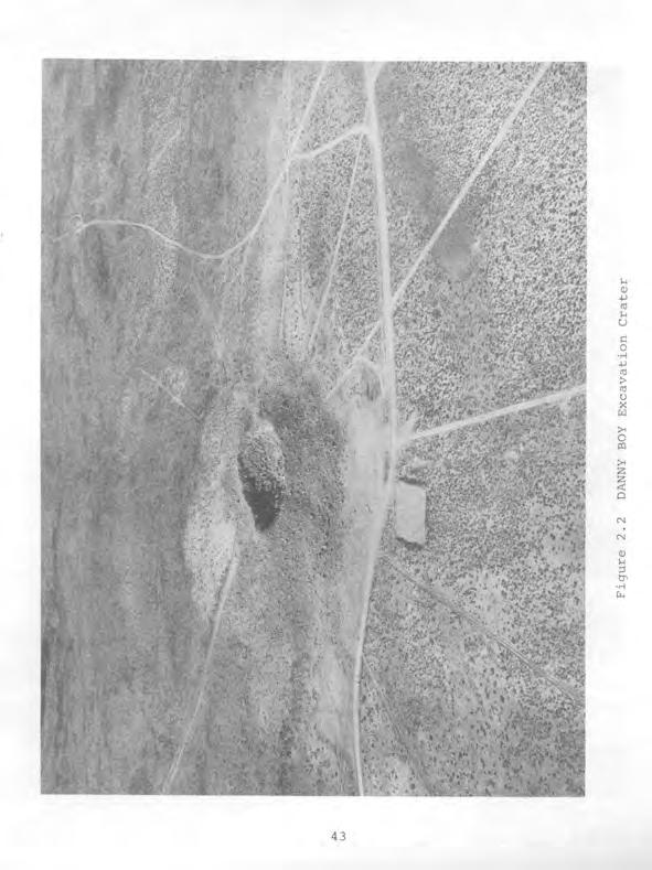
45 subsidence crater. At detonation time, a cavity is formed by vaporized rock under pressure which holds surrounding broken rock in place until the cavity cools sufficiently to decrease pressure. As broken rock falls into the cavity formed by the detona- tion, the chimney of falling rock reaches the surface and a sidence crater forms. Figure 2.1 shows a typical subsidence crater and postevent drilling operation. sub Crater-Type A crater-type nuclear detonation is intended to produce a crater excavated by the nuclear explosion. The nuclear device is emplaced in a shaft at a depth calculated to allow the explosion to eject broken rock from the crater. Some of the material ejected from the crater falls back, resulting in a shallower crater than the original depth of emplacement, and trapping much of the residual radioactivity underground. Figure 2.2 shows the DANNY BOY excavation crater discussed in Chapter Tunnel-Type A tunnel-type nuclear detonation is intended to be completely contained. The nuclear device is emplaced in a mined opening at a depth which usually does not allow chimneying of broken rock to the surface. A tunnel emplacement may be at the end of a single horizontal tunnel into a mountain or mesa, in one tunnel of a complex of horizontal tunnels used for experiments and other nuclear detonations, in a horizontal tunnel from the bottom of a vertical shaft, or in an opening of variable size and shape mined from a tunnel or the bottom of a shaft. Figure 2.3 shows the portal of a typical DOD tunnel complex. 2.2 DIAGNOSTIC TECHNIQUES The major advantage of underground testing was containment 41

46
47

48
49 of radioactive material. One of the major disadvantages was increased difficulty in determining characteristics of a detonation. Photographing a fireball growing in the atmosphere was no longer possible. Samples of a radioactive cloud for analysis no longer could be obtained by sampling aircraft. Measurements of thermal radiation, nuclear radiation, and blast were complicated by the confining underground structures. These disadvantages were overcome by developing new diagnostic techniques, some of which are discussed below Radiation Measurements Measurements of radiations from an underground detonation were made possible by developing a system of remote detectors and cabling to send signals to recording facilities located on the surface. Detectors utilizing various physical characteristics of the radiations to be measured were installed near the nuclear device. High-specification coaxial cable and connectors carried the measurement signals to the surface where electronic equipment recorded the signals. The detector signals were on the way to recording equipment in billionths of a second after a detonation, before detectors were destroyed. These measurement systems required the most advanced electronic technology available. Indeed, considerable research and development was necessary to acquire and refine these capabilities Radiochemical Measurements Because clouds from atmospheric detonations no longer were available to sample, techniques were developed to obtain samples of debris from underground detonations for radiochemical analyses and subsequent yield determinations. The first systems were radiochemical sampling pipes leading directly from the device em- 45
50 placements to filtering equipment on the surface. These pipes required fast-closure systems to prevent overpressure from venting radioactive effluent to the atmosphere after samples were collected. While these systems functioned as intended for most detonations, the systems did not function properly during some tests, and radioactive effluent was released to the atmosphere. Subsequently, the use of radiochemical sampling pipes to the surface was discontinued. The major radiochemistry sampling method which continued in use for shaft detonations was postevent core drilling. The objective of this drilling was to obtain samples of solidified radioactive debris which had collected in a molten pool at the bottom of the cavity produced by the detonation. This method required and resulted in development of precise directional drilling techniques and several advancements in the science of core drilling Line-of-Sight (LOS) Pipes Most of the DOD shaft-type detonations included LOS pipes from the device emplacement to the surface. These pipes allowed effects experiments to be conducted as well as measurement of radiations from the detonations. However, the LOS pipes to the surface required fast-closure systems as did the radiochemical sampling pipes, and use of LOS pipes to the surface also resulted in some releases of radioactive effluent to the atmosphere. Thus, the frequency of DOD shaft-type events, including use of these pipes to the surface, decreased, but the use of horizontal LOS pipes in underground tunnel complexes became frequent and a valuable weapons effects testing system. 46
51 2.3 EFFECTS EXPERIMENTS Weapons effects experiments were the primary reason for conducting DOD underground nuclear detonations. The effects of blast, heat, and radiation from a nuclear detonation in the atmosphere had been studied extensively. Structures, equipment, and materials had been exposed to atmospheric detonations, and military hardware also had been exposed to underwater detonations. Underground testing provided an opportunity to study effects of ground shock and motion, and, of particular importance, the effects of a nuclear detonation environment on equipment and materials at a simulated high altitude. The simulation of a high-altitude detonation was made possible by enlargement and improvement of the LOS pipe system discussed in section Large-diameter pipes hundreds of feet long were constructed underground. The device was emplaced at the end of the pipe. An access tunnel sometimes was constructed parallel to the LOS tunnel, and short tunnels connected the two at intervals. Hatches allowed access to the LOS pipe and sealing of the pipe. Equipment and materials were installed at locations within the LOS pipe. The atmosphere in the LOS pipe was reduced in pressure by vacuum pumps, to simulate a high altitude, before the detonation. Thus, testing of weapons effects was extended from atmospheric and underwater to underground and at simulated high altitudes. 2.4 CONTAINMENT FEATURES AND PROBLEMS Completely containing radioactive material underground while accomplishing diagnostic measurements and effects tests proved to be a major engineering challenge. Original efforts considered only detonation containment in competent rock formations. It was necessary to modify the original efforts to consider zones of 47
52 weakness in rock caused by faults and containment failures caused by diagnostic and experiment structures. In addition, decreased compressibility of rock caused by high water content with subsequent greater ground motion and stress toward the surface caused containment failure. Failures also were caused by unanticipated additional overpressure of secondary gas expansion or steam pressure. The major containment features and problems that evolved are discussed below Shaft Containment Some of the first shaft-type safety experiments were in open shafts. When nuclear yields were produced, open shafts did little to contain the radioactive debris. The first method used to contain detonations in shafts was stemming, or filling the shaft with aggregate and sand after device emplacement. Later, stemming was used that had ground-matching characteristics, such as transmission of shock waves and other properties that would not contribute to containment failure. Keyed concrete plugs at different depths in the shaft stemming sometimes were used. The shaft diameter was enlarged at the plug construction location so the poured concrete plug would key into the ground surrounding the shaft and provide more strength against containment failure. Combinations of concrete and epoxy were used later, and epoxy has replaced concrete as a plug material for some shaft-type emplacements. Radiochemical sampling pipes, LOS pipes, and other openings in stemming and plug containment features had to be closed rapidly after the detonation to prevent venting of radioactive effluent to the atmosphere. Fast-gate closure systems driven by high explosives or compressed air were developed to seal openings. After some of these systems did not prevent releases of effluent to the atmosphere, use of openings to the surface for 48
53 diagnostic or experiment purposes was discontinued for several years until technology improved. Scientific and other cables from the device emplacement to the surface were another source of containment problems. While cables could be imbedded in concrete and epoxy, which effectively prevented leakage along the outside of the cables, radioactive gases under high pressure traveled along the inside of cables as a conduit to the surface. This problem was solved by imbedding the inner components of cables in epoxy at convenient locations or intervals, such as at connectors, in a technique called gas blocking. The most serious containment problems were caused by unanticipated geologic and hydrologic conditions at particular test locations. Even careful and rigorous calculations, engineering, construction, and preparations were inadequate when the presence of a geologic zone of weakness near the detonation point and toward the surface was unknown. Another similar problem was the presence of higher water content than anticipated in rock formations surrounding or near the detonation point. This problem caused (1) greater shock transmission and ground movement by decreasing rock compressibility, (2) additional secondary gas expansion when the water turned to steam, (3) a much higher and longer-sustained pressure from the detonation point toward the surface, and (4) subsequent failure of the geologic or constructed containment mechanisms. Recognizing and understanding geologic and hydrologic conditions at each test location was necessary before these containment problems could be solved. As additional information became available through drilling and intensive geologic studies, these problems were resolved by investigations of proposed detonation locations and application of detailed site selection criteria. 49
54 2.4.2 Tunnel Containment As with shaft-type detonations, containment methods used for tunnel events were designed using basic characteristics of the nuclear detonation. Tunnel configurations were constructed with device emplacements strategically located to cause sealing of the access tunnel by force of the detonation. Additional containment features were used to contain radioactive debris. A short distance from the projected self-sealing location toward the tunnel entrance (portal), one or more sandbag plugs were installed. Two plugs, each about 60 feet in length, were a typical installation. Farther toward the portal, and before entering the main tunnel in a complex with more than one test location, a keyed concrete plug with a metal blast door was constructed. The blast door was designed to contain any gases, with pressures up to 75 pounds per square inch (psi), that might penetrate the plugs. Also as with shaft-type detonations, the unknown presence of undesirable geologic and hydrologic conditions sometimes caused venting of radioactive effluent either through the overburden (ground above the tunnel) to the surface, through fissures opened between the detonation point and the main tunnel, or through the plugs and blast door to the main tunnel vent holes and portal. More substantial containment features evolved as containment problems became better understood and tunnel events became more complex. Generally, the sandbag plugs became solid sand backfill hundreds of feet long, and the blast door evolved into a massive overburden (equivalent) plug separating the test location tunnels from the main tunnel. The plug typically was 20 to 30 feet of keyed concrete with a large steel door containing a smaller ac- 50
55 cess hatch, and was designed to withstand overpressure up to 1000 psi. Use of the LOS pipe in tunnel events necessitated development of additional containment and closure systems. The LOS pipe tunnel and its access tunnels were separated from the main tunnel by the overburden plug. Additional containment and closure systems were for protection of the LOS pipe and its experiments as well as preventing release of effluent to the surface. Generally, the tunnel volume outside of the pipe was filled with stemming, grouting, or by other means to facilitate containment, while the inside of the pipe and its experiments were protected by fast-closure systems. Various systems were in use including compressed air or explosive-driven gates and doors which closed off the LOS pipe from the detonation within a small fraction of a second after detonation time. The same gas blocking techniques as used in shaft events were used to prevent leakage of radioactive gases along or through cables from the diagnostic and experiment locations to the surface. Additionally, a gas seal door usually was installed in the main drift nearer the portal than the overburden plug. Utility pipes, such as for compressed air, that passed through stemming and plugs also were sealed by closure systems. Containment systems evolved to the point that release of detectable radioactivity to the atmosphere seldom occurred. 2.5 TUNNEL AND DRILLING AREA ACCESS REQUIREMENTS Access to underground workings and drilling sites was con- trollcil for a number of reasons. During construction, safety of both workers and visitors in these locations could have been 51
56 jeopardized by carelessness or seemingly harmless activities of untrained and uncontrolled visitors. When security-classified material was in these locations, only personnel with appropriate security clearances were permitted access. The presence, or anticipated presence, of radioactive material in these locations required access control for radiological safety purposes. Access requirements established for the above purposes are discussed below Tunnel Access Control During construction and preparations for a DOD event in a tunnel or other underground working, the tunnel superintendent was responsible to the project manager for safety of personnel underground. All persons going underground, or the supervisors of working groups, were required to enter appropriate information in the tunnel log book. Visitors and other personnel not assigned to work in the tunnel obtained permission for entry from the superintendent, or his representative, and were apprised of tunnel conditions and safety regulations. In the event of an accident or other emergency condition underground, the log book provided information on numbers of personnel and their locations underground. When classified material was in the tunnel, and during initial reentry after an event, the DOD Test Group Director, or his representative, was responsible for entry and safety of personnel underground. Security personnel checked for proper security and entry clearances, and maintained records of all personnel entering the tunnel. Control of tunnel access reverted to tunnel management per- sonnel after tunnel reentry and recoveries. Entry procedures and use of the tunnel log book were then as discussed above. 52
57 Additional access controls were instituted for radiological safety purposes after an event or during construction and event preparations when radioactivity from a previous event could be encountered. Part or all of a tunnel complex would be established as a radiation exclusion (radex) area. All persons entering radex areas were logged on Area Access Registers by radiological safety personnel. Names and organizations represented were listed. Radiation exposures for the year were listed upon entry and added to with self-reading pocket dosimeter measurements upon exit. This was to assure that personnel approaching radiation exposure guide limits would not be allowed to enter radex areas and accumulate exposures above guide amounts. Before entry, personnel were dressed in anticontamination clothing and respiratory protection as needed for the particular radiological conditions in the tunnel. Upon exit, anticontamination clothing was removed, personnel were monitored for radioactive contamination, and decontamination was accomplished, if necessary Drilling Area Access Control Access to drilling areas was controlled by the drilling superintendent and the DOD Test Group Director for the same reasons as controlling access to underground workings. During drilling of an emplacement shaft, and during postevent drillback operations to recover radioactive core samples, personnel safety and compliance with safety regulations were emphasized continuously. During preevent drilling activities, all visitors were required to contact the drilling superintendent before entry to the drilling site. Names of visitors and purposes of visits were entered in the daily drilling report, and it was assured that vi- 53
58 sitors had hard hats and understood safety regulations. When classified materials, including the nuclear device, were brought into the area for emplacement, the DOD Test Group Director controlled access to the area with assistance from security force personnel as in similar tunnel operations. After the event, when the drill site was a radex area, during classified material removal, or during postevent drilling, both security and radiological safety access controls were in effect as discussed under Tunnel Access Control. 2.6 INDUSTRIAL SAFETY CONSIDERATIONS Implementation of an effective industrial safety program was an important part of any heavy construction operation. Mining and drilling operations had a particularly high accident potential. These operations at the NTS involved additional safety problems resulting from detonation-induced unstable ground conditions and potential for encountering toxic gases and mixtures, and radioactivity. Tens of miles of underground workings were constructed. More depth of big holes (three-foot diameter or larger) were drilled than the total drilled in the rest of the world. Directional and core drilling to recover radioactive debris samples after underground nuclear detonations advanced the science of these drilling techniques. These operations were accomplished under unusual conditions with accompanying difficult safety problems. However, the lost-time accident frequency for the NTS support contractor employing most of the NTS personnel (REECO) was only one-tenth of the frequency for the heavy construction industry at large (as determined by annual surveys and reports for 300 heavy construction corporations). This excellent safety 54
59 record was attained by continuing attention to indoctrinating and training NTS personnel, investigating and determining causes of accidents at the NTS, implementing and enforcing safety regulations, and, most important, maintaining the safety awareness of NTS personnel. This was a joint effort by the DOE and DNA, and their predecessors, and by the many other government agencies and contractors at the NTS. Administered by REECo, the safety program enjoined all NTS personnel to conduct operations safely, and was exemplified by the signs on the portal of a typical DOD tunnel complex as shown in Figure 2.3, including "Safety With Production Is Our Goal." The safety procedures for all NTS operations are voluminous and cannot be included in this report. Appendix C of this report is an example of pertinent safety procedures; General Tunnel Reentry Procedures for Department of Defense and Sandia Laboratory Tests. As these procedures indicate, several aspects of industrial safety are interrelated. Information on monitoring levels of radioactivity and personnel exposures to radiation is presented in the next section, 2.7 Radiological Safety Procedures. Monitoring of toxic gases and explosive mixtures was an important aspect of safety in underground workings, on drill rigs, and in drillhole cellars (enlarged first part of drillhole for valving and other equipment). Toxic gases and explosive mixtures were created by both the nuclear detonations and the mining and drilling operations. The Draeger multi-gas detector and the MSA explosimeter were used to detect such gases. The Fyrite or J&W oxygen indicators were used to determine the oxygen content of the working atmosphere. Requirements were that tunnel and drill rig breathing atmosphere contain at least 19.5 percent oxygen. During the period covered by this volume, it was required that breathing air contain less than the following 55
60 levels of toxic gases and explosive mixtures: Gases Maximum Concentration Carbon monoxide, CO Carbon dioxide, CO2 Nitric oxide plus nitrogen dioxide, NO + NO2 Nitrogen dioxide, NO2 Explosive mixtures 50 ppm 5000 ppm 25 ppm 5 ppm 10% of LEL (lower explosive limit) Procedures for controlling explosive mixtures and toxic gases after each test event are discussed in event chapters as appropriate. 2.7 RADIOLOGICAL SAFETY PROCEDURES Procedures were developed in an effort to evaluate radiological, toxic, and other hazards, and protect workers and the public from unnecessary exposures. The following were primary written procedures and implementation methods used at the NTS from 1962 through U.S. Atomic Energy Commission Nevada tion - Standard Operating Procedure, logical Safety Test Site Organiza- Chapter 0524, Radio- Chapter 0524, which appears as Appendi x D to this volume, defined responsibility, and established criteria and general procedures for radiological safety associated with NTS programs. Some but not all of the major areas discussed are film badge procedures, radiation surveys, entry into controlled areas and radiation exposure guides. Roles of the onsite REECo Radiological 56
61 Safety Division (Radsafe) and the offsite United States Public Health Service (PHS) also are defined in NTSO-SOP Chapter Standard Operating Procedures for the Radiological Safety Division, REECo, dated January 1961 These procedures were prepared to address in more detail the radsafe aspects discussed in the latest revision of NTSO-SOP Chapter The same major areas were discussed but in a more specific manner REECo Radiological Safety Division Information Bulletins The Information Bulletins were formalized instructions for performing specific radiological safety and industrial hygiene tasks. They defined a situation, delineated responsibility, and described methods to be used in performing the task Detailed procedures as outlined in REECo Radiological Safety Division Branch Operating Guides These were informal internal procedures written to address a particular known or anticipated operational activity Implementation of radiological procedures required equipment, devices, and capabilities for monitoring radiation levels in the environment, and monitoring external and internal exposures of personnel. Equipment and devices used for these purposes, and necessary capabilities were as follows: A. Portable Radiation Detection Equipment Eberline PAC 3G (alpha) 57
62 Eberline PAC 1SA (alpha) Technical Associates Juno SR-3 (medium range alpha, beta, gamma) Floor Monitor (alpha) Floor Monitor (low range beta, gamma) Portal Monitors (low range beta, gamma) Beckman MX-5 (low range beta, gamma) Eberline E-112 (low range beta, gamma) Precision 111 (low range gamma) Eberline E-500 (high range gamma) Victoreen Radector (high range gamma) Jordan AGB 10 KG SR Rad Gun (high range gamma) uw-1, underwater (gamma) Gateway Monitor (gamma alarm) Nuclear-Chicago 2715 Nemo (neutron) PNC-1 (neutron) FN-la (fast neutron) B. Air Sampling Equipment High-volume air samplers (Staplex) Low-volume air samplers (Gelman) Continuous and sequential samplers Fallout and resuspension trays C. Laboratory Analysis Capability The radiological safety laboratory analyzed air, soil, water, surface swipe, fallout tray, nasal swab, urine, and wound swab samples for some or all of the following activities: gross alpha and beta, gross fission products, tritium, strontium-90, plutonium-239, and spectrographic analysis of specific gamma-emitting radionuclides. The laboratory also analyzed some of the above samples for nonradioactive materials, such as be- 58
63 ryllium, through use of an emission spectrograph and by wet chemistry procedures. A spectrophotometer was used to analyze other materials. D. Monitoring of Personnel Exposures A DuPont type film packet with a type 508 low range component and a type 834 high range component was used as the personnel dosimeter of record. Ranges of the two components were 30 mr to 10 R, and 10 R to 1000 R, respectively. The packet was wrapped with a 28-milthick lead strip covering an area one-half inch by one inch on each side. The packet was in a four-mil-thick plastic bag. A colored tape across the top of the bag indicated validity for a given month. The bag was attached to the security badge with a clip, and security guards assured that all personnel entering NTS wore a valid film dosimeter. Film badges were exchanged routinely each month for all individuals, and upon exit from a radex area when it was suspected that an individual had received 100 mr or more of exposure. Personnel entering radex areas also were issued selfreading pocket dosimeters which indicated accumulated exposure upon exit. Pocket dosimeter readings were entered on Area Access Registers and added to yearly and quarterly accumulated exposures from the automated daily NTS radiation exposure report. Pocket dosimeter readings were only estimates because several factors caused these readings to be less accurate than the doses of record determined after processing of film packets. This use of Area Access Registers helped to maintain 59
64 personnel exposures below the whole-body exposure guides in Chapter 0524, 3000 mrem per quarter and 5000 mrem per year. Personnel with exposures from the report plus any dosimeter reading since the report in excess of 2500 mrem per quarter or 4500 mrem per year were advised not to enter radex areas and their supervisory personnel were so notified Additional methods used for control of radex areas and prevent spread of contamination to uncontrolled areas were follows: to as A daily log book was maintained by Radsafe monitors for each of the radex area locations. These log books were used to record the following information: A. Work accomplished: Where people worked and what work was accomplished were briefly described. Any unusual conditions, such as equipment failure and operational difficulties, were listed. B. Visitors: First and last names of visitors were entered. Their destination and reason for their visit were included where possible. Time they exited the area and results of personnel monitoring were recorded. C. Unusual occurrences: Any unusual events which occurred during the shift were recorded. This entry included accidents, high-volume water seepage, or any other occurrence of an unusual nature. 60
65 D. Surveys and samples: Information collected was recorded as follows: Survey type - Routine or Special* Sample type - Routine or Special* *Indicate requester's name for Special type. E. Date and signature: The date and shift were entered at the beginning of each work period and the log book was signed before leaving the shift. Personnel leaving radex areas removed anticontamination clothing and equipment and placed them in special containers for later laundering or disposal at the designated NTS burial site. Personnel then were monitored to assure radiation levels were below those listed on page 284 of Appendix D, NTSO-SOP Chapter 0524, Radiological Safety. Personnel decontamination was accomplished if radiation levels were above specified limits. Decontamination usually was accomplished by vacuuming, removing radioactive particles with masking tape patches, washing hands or localized skin areas with soap and water, or showering with soap and water. Vehicles and equipment removed from radex areas were monitored to assure radiation levels were below those listed on pages 284 and 285 of Appendix D for release on the NTS. Limits for release of vehicles and equipment off the NTS were 0.3 mrad/h beta plus gamma radiation at contact and no detectable alpha activity. Vehicles and equipment normally were decontaminated by vacuuming and steam cleaning with water or detergent solutions. 2.8 TELEMETERED MEASUREMENTS OF RADIATION LEVELS Beginning in the early 1960's, various applications of radi- 61
66 ation measurement telemetry were developed at the NTS to determine radiation levels at critical underground and surface areas following nuclear detonations. Multi-detector systems with range capabilities from 0.5 mr/h to 500 R/h and from 10 mr/h to 10,000 R/h, continuously monitored locations of concern after being emplaced and calibrated prior to each test event. Ion chamber detectors were hard-wire-linked by telephone trunk lines to exposure rate meters at a central console in Control Point Building 2. Detector locations were as far as thirty-five miles from the console. These remote radiation monitoring systems provided data for reentry personnel participating in radiation surveys and recovery operations after detonation of a nuclear device. The systems aided in substantially reducing radiation exposure of personnel involved in reentry programs, and were useful in detecting any venting or leaking of radioactive effluent to the atmosphere from an underground detonation Evaluation and Development of Telemetry Systems The radiation telemetry systems developed and used had specific applications depending upon distance, terrain, environment, and operational needs. The detection units, systems, and components being studied and developed in 1962 were the following: A. Remote Data Station (RDS) The RDS unit was built by the National Bureau of Standards. The unit used a Geiger tube as the detecting element, and the signal was transmitted by hard wire. The DC current from the GM tube was converted to frequency by running it through an oscillator circuit, and was read out as cycles per second which could be equated to roentgen rate readings. The range of the RDS was 10 62
67 mr/h to 10 R/h. This unit was very efficient for transmitting long distances, but had limited exposure rate range and shock resistance capability. The unit was modified for use at NTS, but its use was discontinued later because the measurement range was inadequate. The application of RDS units to a telemetry system at NTS is discussed in Chapter 3. B. Area Remote Monitorina Station (ARMS) These units consisted of Tracerlab TA-6 (GM tube) gamma detectors with Model 261 direct readout meters. The meter had a two-range scale, 0 to 10 R/h and 0 to 100 R/h. The hard-wire system had a 35-mile transmission range, and had limited shock resistance capability. Ground shock caused failure of the units (see Chapter 31, and their use was discontinued. C. Radector Monitoring Station (RMS) These units had Radector portable detector electronics including the Neher-White ionization chamber used for remote radiation detection. The stations were the most versatile telemetry detectors, could transmit signals 35 miles by hard wire, afforded direct readout, and ranked highest in shock resistance. Descendants of these units were part of the Remote Area Monitoring System (RAMS) later used for most DOD underground test events. D. Radio-Link Telemetrv This EG&G-developed system was a line-of-sight radiolinked system, transmitting the desired information on VHF frequencies from a field unit to a main control console. The ionizing radiation-induced signal was then 63
68 read out as cycles per second on a signal event-perunit-time meter. The system did not have desired range or battery life for all applications but was valuable in areas where there were no hard wires available. E. Well Logging Unit This unit was a Jordan ion chamber gamma detector with a glass-head thermister capable of obtaining gamma radiation measurements or temperature either separately or simultaneously, and was used at drill sites for postevent hole radiation and temperature measurements. Radiation detection ranges were from 0.5 mr/h to 500 R/h and temperature measurement ranges were from 0 F to 350'F Use of Telemetry Systems at NTS Permanently establ ished remote radiation detector stations could be monitored continuously at living areas, work areas, and other locations throughout the NTS after each test event. Figure 2.4 shows a typical arrangement of permanent remote detector stations located throughout NTS. Some changes in location were made when activities in some areas ceased or were renewed. For shaft-type events, a typical array of remote detectors installed for the event is shown in Figure 2.5. Eight or more detectors were installed in circular patterns at two or more distances from surface ground zero. Detectors sometimes were concentrated in the predicted wind direction, and the distances of circular arrays from surface ground zero could be varied with the predicted yield and wind velocity. Remote detector placement on the surface for tunnel-type events was determined by the location of stations of interest to 64
69 R5 0 _!! 0 IO ,OOOFT 0 PERMANENT TELEMENTRY STATIONS Figure 2.4 Typical Permanently Established Remote Kaalaclorl Detector Stations Operated Continuously Throughout the NTS 65
70 Figure 2.5 Typical Remote Radiation Detection Monitoring System for Shaft-Type Emplacement Site. 66
71 surface reentry personnel and accessible installation locations at greater distances from the tunnels. Figure 2.6 shows a typical surface remote detector array for a tunnel event. Additional detectors were located within the tunnels to provide information for tunnel reentry. Approximately 200 detector channels were available for the permanent, shaft-type, and tunnel-type arrays. Readings from event-related and permanent telemetry detectors were recorded from zero time until it was determined that no release of radioactivity had occurred, or until any released radioactive effluent had decayed to near-background levels at telemetry detector stations. 2.9 AIR SUPPORT REQUIREMENTS The AFSWC provided direct support to the NTSO for DOD underground tests, and other Air Force organizations provided support under AFSWC control as described in section of this report. Complete Air Force support was available for the DANNY BOY event, a DOD cratering event discussed in Chapter 4 of this report, and during the remainder of However, less air support was required as the probability of venting radioactive effluent to the atmosphere decreased with development of more effective containment techniques Changes in Air Support Requirements After 1962, Air Force cloud sampling and cloud tracking aircraft generally were not required, except for AEC cratering events where radioactive effluent clouds were anticipated. The value of analyzing particulate and gaseous cloud samples to determine characteristics of a detonation decreased. Passage of the radioactive effluent through variable amounts and tempera- 67
72 PROBE PLACED ON RIM (JUNCTION OF MERCURY HWY AND AREA I2 A 30 IN LINE FROM A REMOTE RADIATION DETECTOR Figure 2.6 Typical Remote Radiation Detection Monitoring System for Tunnel-Type Emplacement Site 68
73 tures of rock and other media selectively retained some radio- nucl ides underground, and changed the known ratios of fission products previously used during analysis of atmospheric detonation cloud samples. The first change in cloud sampling and tracking support was to a lighter Air Force aircraft, the U-3A, with an Air Force pilot and PHS monitor. The PHS monitor also performed aerial monitoring of selected locations near surface ground zero and along the path of any effluent cloud. This air support later was performed by PHS and contractor personnel in their own aircraft. The Air Force L-20 aircraft, with an Air Force pilot and a security guard from the NTS security force, continued to provide security sweep coverage of the NTS perimeter and test areas until 1968, when the type of aircraft used was changed to a helicopter. Perimeter sweeps were conducted daily, during reasonable flying weather, to assure that unauthorized. vehicles were not entering the NTS over rough terrain or around security barricades on secondary roads. Air security sweeps of the immediate test area were conducted for a few hours before each detonation to assist in clearing the test area and to assure that unauthorized vehicles were not approaching it from directions not controlled by manned security stations. Air support for photography missions during test events and initial radiation surveys after each event did not change. Helicopters and Air Force pilots generally were used with contractor photographers and Radsafe monitors Radsafe Support for Indian Springs AFB Radsafe support facilities had been established at ISAFB during atmospheric nuclear device testing series. During 1962 tests, and subsequent DOD underground tests requiring support 69
74 aircraft staged from ISAFB, REECo provided all radsafe support functions available at the NTS. This included monitors stationed at the ISAFB radsafe quonset facility, and a complete stock of film dosimeters (badges), radiation detection instruments, and anticontamination clothing and equipment for use by aircrews and ground crews. Radsafe monitors issued and exchanged film dosimeters (badges), issued self-reading pocket dosimeters, dressed Air Force personnel in anticontamination clothing, provided respiratory protection equipment, monitored aircraft and personnel after events, decontaminated personnel, and assisted ground crew personnel with decontamination of aircraft. Figures 2.7 through 2.9 show decontamination and monitoring of typical B-57 cloud sampling aircraft used from 1962 until the type of sampling aircraft was changed. Aircrews departing from contaminated aircraft removed anticontamination clothing and equipment at the radsafe facility, showered, and were monitored to assure complete decontamination before they dressed in regulation clothing and were released. Ground crews who removed particulate and gaseous cloud sample collection media from aircraft or who participated in aircraft decontamination were subject to the same personnel decontamination procedures Radsafe Support for Helicopters Although ISAFB radsafe support extended to all participating aircraft, special helicopter radsafe procedures were implemented because these aircraft landed at NTS and staged from helicopter pads located east of Mercury Highway at the Control Point area and near a Test Director's Forward Control Point (FCP) established for a particular underground event. Helicopter pilots 70

75

76
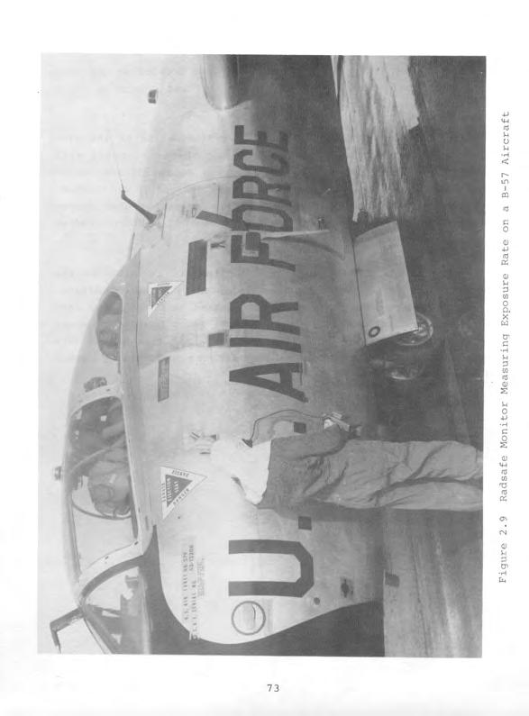
77
78 usually landed at these locations, and were briefed at the Con- trol Point or particular Forward Control Point regarding their scheduled missions or other operational missions. If the mission involved possible contamination of the aircraft, Radsafe monitors lined the floor of the aircraft with plastic, or kraft paper, and masking tape to facilitate decontamination. Pilots and crew members were dressed in anticontamination clothing and provided with film badges, pocket dosimeters, and respiratory protection equipment if airborne radioactive material was anticipated. Upon completion of missions, helicopters returned to the landing pads where they were decontaminated by Radsafe monitors. Pilots and crew members were decontaminated at an adjacent forward Radsafe base station, or at Control Point Building 2 where pocket dosimeters were collected and read, and film badges were exchanged if exposures of 100 mr or more were indicated by pocket dosimeters. 74
79 CHAPTER 3 HARD HAT EVENT 3.1 EVENT SUMMARY The HARD HAT event was a DOD underground nuclear detonation with a yield of 5.7 kt conducted at 1000 hours Pacific Standard Time (PST) on 15 February 1962 at shaft site U15a in Area 15 of the NTS. The device was emplaced in a 36-inch diameter shaft drilled in granite at a depth of 943 feet below the surface elevation of 5,114 feet Mean Sea Level (MSL). Cavity collapse occurred approximately eleven hours after device detonation. Minor amounts of radioactive effluent were released after cavity collapse and were detected onsite only. HARD HAT was primarily an underground structures program with instrumentation in a nearby access shaft and tunnel complex. The purpose of the HARD HAT event was to test capability of underground structures to withstand strong motions generated by an underground nuclear detonation in hard rock. There were 25 DOD scientific projects conducted by government agencies and contractors. Work necessary to conduct these projects included constructing an 800-foot-deep access shaft 800 feet southeast from the device emplacement shaft; constructing a 600-foot tunnel leading from the access shaft toward the emplacement shaft; constructing three arcuate test drifts intersecting the tunnel; drilling 21 holes from the underground complex; and drilling eight holes about 1,000 feet deep from the surface. Figure 3.1 is a photo of the access shaft headframe and surrounding structures, and Figure 3.2 is a sketch of the underground complex. 75
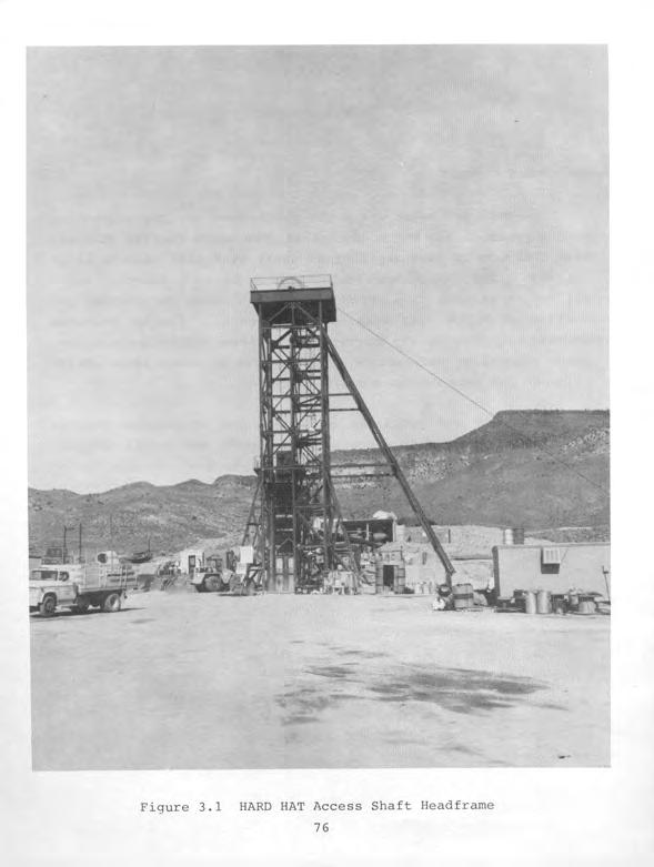
80
81 SGZ -N STATION 15 SHAFT COLLAR 784 FT. 800 FT. 2 I /, /, 943 FT. TEST DRIFT TEST DRIFT A B ZERO POINT STATION U15a Figure 3.2 HARD HAT Underground Complex 77
82 3.2 PREEVENT ACTIVITIES Responsibilities The DOD Test Group Director was responsible for safe.conduct of all HARD HAT project activities in Area 15. Responsibilities of AEC and AEC contractor personnel were in accordance with established AEC/DOD agreements or were the subject of separate action between Field Command, DASA, and the AEC Albuquerque Operations Office. SC was responsible for providing, emplacing, and arming the device, and stemming and installation of necessary measuring devices and equipment. SC and LASL were responsible for radiochemical analysis to determine yield. EG&G was responsible for providing and installing timing and firing circuits. The DOD was responsible for preevent installation and postevent removal of equipment necessary for its project activities Planning and Preparations Project materials and equipment installed included 48 structural test sections and 450 gauges in the underground complex, instruments in 21 underground and eight surface holes, and numerous seismic and other scientific stations on the surface. The majority of measurements had to be obtained or recovered during several weeks of postevent access to the structures. These experiments were not radiation sensitive, but reentry had to be accomplished within five weeks to prevent losses due to corrosion. The "HARD HAT Reentry Plan" described preevent preparations and postevent procedures used to assure safe and economical reentry within the desired five-week period. Stemming design in access tunnels incorporated necessary provisions to maximize safety of reentry. Geophones were installed to monitor cavity activity and assure collapse before reentry. 78
83 There were to be five separate reentry teams, each of which had a separate and specific mission: Team 1 - Surface Radiation Survey Party Team 2 - Shaft Collar Group Team 3 - Shaft and Tunnel Reentry Party Team 4 - Rescue Team Team 5 - Working Party Recall of the reentry teams could be made for any of the following circumstances: 1. any break in communications between Team 2 and Team 3, 2. by request of the Test Group Director or Reentry Chief, 3. upon decision of the Chief of Shaft and Tunnel Party, and/or 4. when any member of Team 3 indicated a McCaa (breathing apparatus) oxygen supply of less than 30 atmospheres.' Reentry was not to be made before the ventilation system had been turned on and samples of air monitored at the remote blower, or later at the shaft collar. Reentry was not to be made beyond the ventilated area in the shaft. A remotely-controlled blower was installed on the surface during preevent button up at a distance of approximately one-half mile from the shaft, and a line run along the ground to the shaft collar. This line was connected by a flexible coupling to the vent pipe at the shaft collar. Remote controls for the blower were located in the Forward Control Point. A single line was run from a single blower in the shaft collar area down the shaft and tunnel, with junctions at the "A","B", and "C" arcuate drifts for short branches into the wings of the drifts. Air sampling pipes were installed through both the sandbag 79
84 plugs and the gas seal door prior to the event. These were to be used during reentry to determine breathing atmosphere conditions just forward of the plugs and door. A two-inch diameter flexible hose was installed and anchored in the "B" and "C" arcuate drifts. Compressed air was to be pumped through these drifts to clear any gases before tunnel reentry. The hose was designed for simple connection to compressed air lines. A. Radiological Safety Support Detailed radiological safety reentry plans were submitted to participating agencies prior to the event. Test area maps with appropriate reference points were prepared. Reference stakes, fallout trays, radiation decay recorders, air sampling equipment, film dosimeter packets, and other dosimetric devices were positioned in the test area. Reentry routes into the test area were established during "dry runs." Party monitors were briefed regarding reentry, sample recovery, manned stations, and security station requirements. Radsafe had 12 personnel stationed at the DOD Test Group Director's FCP prior to the HARD HAT detonation to perform surveys and provide emergency support as directed; provide and issue anticontamination equipment, portable instruments, and self-reading dosimeters; operate area control check stations; and perform personnel, equipment, and vehicle decontamination as required. All personnel at manned stations were provided with appropriate anticontamination clothing and equipment, and Radsafe monitors Were in attendance. Anticontamination materials available included cover- alls, head covers, shoe covers, full-face masks, sup- 80
85 plied-air breathing apparatus, plastic suits, gloves, plastic bags, and masking tape. B. Telemetry Support A radiation telemetry system was installed with the readout located in CP-2. Telemetry readout data were to be relayed to CP-1 and the FCP by telephone and network (net) 3 radio. SC and Radsafe personnel placed five ARMS units at the following surface locations: feet north of Surface Ground Zero (SGZ) 2. Radiochemical sampling pot number 1 (25 feet northeast of SGZ) feet east of shaft collar 4. Trailer number 82 (about 3,000 feet southeast of SGZ) 5. Stake L-67 (about 2,000 feet southeast of SGZ) Radsafe personnel installed five RDS units underground and on the surface as follows: 1. In the B6A section of "B" drift 2. Station 4+65 (465 feet from shaft) in the main tunnel (at the intersection with "B" drift) 3. Station 0+40 (inner side of gas seal door) 4. Station 0+35 (outer side of gas seal door) 5. West of shaft collar on the surface c. Securitv Coveraue At six hours prior to device detonation, security personnel established test area control and muster stations. The Forward Control Point and muster station for Area 15 were establ ished about four miles southwest of 81
86 SGZ on the Circle Road between Area 8 and Area 10 (see Figure 1.5). In addition, four security stations were established to control roads leading to Area 15. A screening station was set up near the FCP at the observer area. The final security sweep of all closed areas was completed three hours prior to device detonation. U.S. Air Force (USAF) and security personnel completed a final sweep of Areas 8, 10 and 15 by 45 minutes before zero time. D. Air Support An Air Force U-3A aircraft, pilot, and co-pilot were made available to a PHS Aerial Monitoring Team for cloud tracking purposes. According to the PHS offsite report for HARD HAT, the principal instrument used was a Precision Model 111 scintillator, with an added transistorized amplifier feeding an Esterline-Angus strip-chart recorder, and having a maximum range of 5 mr/h in six scales. Approximately one hour prior to device detonation, USAF and LRL personnel in an Air Force H-21 helicopter took an upwind position from SGZ in readiness for event photography coverage. In addition, approximately 15 minutes prior to device detonation, the U-3A aircraft departed from ISAFB to orbit over Frenchman Lake (Area 5) in readiness for cloud tracking, if required Late Preevent Activities On 14 February 1962 (D-l day), U.S. Coast & Geodetic Survey (USC&GS) personnel made final adjustments to instruments at eleven seismic stations. These were located at distances ranging from 2,400 to 8,400 feet from SGZ. LRL personnel checked elec- 82
87 tronic recording instruments and performed dry runs at Trailer 39 which was located about 2,000 feet from SGZ. SC personnel checked out instrumentation in their diagnostic trailers located about 3,000 feet from SGZ. Four DOD personnel calibrated equipment in the area from SGZ out to approximately 2,000 feet in all directions, and participated in dry runs. DOD personnel also calibrated equipment and participated in dry runs in the tunnel complexes and at SGZ. SC personnel emplaced high explosives (HE) for microbarograph calibration shots. A Test Manager's weather briefing was conducted at 2200 hours on 14 February At this briefing, panels of administrators and experts reviewed weather forecasts, studied the projected path of any radioactive effluent, and decided that conditions were favorable for conducting the event as scheduled. 3.3 EVENT-DAY AND CONTINUING ACTIVITIES On D-day, from midnight to three hours before scheduled device detonation, DOD personnel activated recording station equipment, checked moisture probes, started magnetic tapes, and assured operation of surface telemetry units. During this same time period SC personnel activated equipment, armed microbarograph calibration shots, and proceeded to U15a for device arming. The final weather briefing for the Test Manager and Advisory Panel was conducted two hours prior to planned device detonation. At this time, SC personnel requested and received permission from the Test Group Director to arm the device. Required countdowns began on radio nets 1, 2, 6, and 8. At ten minutes prior to device detonation the siren on the CP-1 building ran for 30 seconds, and the red lights on top of the building were turned on until after detonation time. 83
88 HARD HAT zero time was 1000 hours on 15 February Underground telemetry units in the "B" drift and in the main tunnel 465 feet from the shaft failed to respond after zero time because lines were damaged. Remaining telemetry units underground and on the surface did not detect radiation intensities above background from device detonation through 1630 hours when telemetry readouts were secured. Two microbarograph calibration shots were scheduled to be fired at five and eight minutes, respectively, after zero time. One microbarograph shot misfired but the problem was corrected and the shot was fired two hours after device detonation. A USAF/PHS aerial monitoring team entered the area 40 minutes after device detonation. Aerial monitoring was conducted from one mile to 15 miles downwind for the next 45 minutes. Results of aerial monitoring indicated no measurable release of activity immediately following the event. Two Radsafe initial survey teams in vehicles were released by the DOD Control Officer at 1200 hours after the second microbarograph shot. Ground radiation surveys were made both at fixed locations and during sweeps through the area. One of the sweeps was a 360-degree circuit of SGZ at a radius of 100 feet. No measurement indicated radiation above background. The three radiochemistry sample collection pots on the sampling pipe from SGZ to 50 feet northeast of SGZ read background, and survey monitors reported the lids were off the pots. Apparently, the detonation or pipe closure devices closed the pipe before effluent samples were obtained. Industrial hygiene sampling measurements made during the radiation surveys indicated no detectable concentrations of explosive mixtures or toxic gases. At approximately 1315 hours, the DOD Control Officer pro- 84
89 ceeded into Area 15 and established an FCP approximately 200 feet southeast of the shaft collar. At this time, the Radsafe check station trailer was moved to within 150 feet of the shaft on the east. The two Radsafe survey teams were left at the newly established FCP to act as monitors for recovery parties, with instructions that no personnel were to enter within 100 feet of the SGZ area unless specifically authorized by the DOD Control Officer or a delegated representative. Recovery of experiment data on the surface in the test area continued for several hours. Radiation measurements made by party monitors were not above background, radex areas were not established, and film badges were not exchanged upon exit from the test area. At 1600 hours, after statements by test personnel that the detonation apparently was contained, the DOD Control Officer delegated area control to security force and Radsafe personnel with no special instructions. Telemetry readouts were secured by Radsafe at 1630 hours. All recovery personnel were clear of the test area by 1800 hours, and the Radsafe monitor in the SGZ area moved back to the security roadblock at the junction of the shaft and SGZ access roads about 700 feet south of the shaft. Also at this time, the monitor at the Radsafe checkpoint secured the trailer and left the area. The Radsafe monitor at the security roadblock drove to the shaft to make a survey at 1930 hours. He detected no CO, C02, NO, NG2, hydrocarbons, or explosive mixtures. However, he detected 18 mr/h at the flexible coupling to the shaft vent pipe. At 2010 hours, he again detected 18 mr/h at the shaft, but no radiation above background at the security roadblock. At 2053 hours, the Radsafe monitor and the security guard reported hearing two rumbles from the SGZ area but felt no ground movement. The underground detonation cavity had collapsed. The roadblock was moved 200 feet farther south as a precautionary 85
90 measure, and the Radsafe supervisor arrived at 2120 hours. The two Radsafe personnel proceeded to the shaft collar and measured 100 mr/h and no toxic gases or explosive mixtures at 2155 hours. A pungent odor was detected as they drove toward SGZ. They retreated and approached SGZ from upwind. After measuring 50 mr/h at the SGZ plug, and no CO or C02, they quickly left the area to avoid the pungent odor. Another survey of SGZ was made at 0130 hours on 16 February. The maximum reading was 500 mr/h near the SGZ plug base. No CO or explosive mixtures were detected, but sulfurous odors were noted in the area. Several fissures in the SGZ area read background. At 0630 hours, the plug base still read 500 mr/h, and a 40- foot-long fissure read 200 mr/h with 200 ppm C02, 400 ppm CO, and no detectable explosive mixtures. Radioactive gases displaced by cavity collapse apparently were coming up the radiochemical samp- ling pipe. A measurement inside sample pot number 2 indicated 10 R/h, and three feet from the pot the reading was 100 mr/h. Exposure rates in areas not near fissures or sample pots averaged about 10 mr/h. A survey of the shaft collar area at 0715 hours indicated vent line contact and general exposure rate readings of 6 mr/h maximum. The security roadblock continued to assure that only Radsafe personnel entered the area. Operation of the radiation telemetry system resumed at 0815 hours. Surface units continued to indicate less than the detectable 10 mr/h. Apparently, the unit 100 feet north of SGZ failed to detect the gaseous radioactivity or malfunctioned, and the unit near sample pot number 1 malfunctioned, because both continued to indicate no positive readings. A survey of SGZ at
91 hours indicated nothing above background at the fissures, but 8 R/h at contact with sample pot number 1. Table 3.1 shows readings from the functioning underground telemetry units. Gaseous radioactivity displaced by cavity collapse apparently had been forced through fissures into the underground tunnel complex. Maximum readings were greater than 10 R/h inside the gas seal door, and 160 mr/h outside the door. A PHS aerial monitoring team arrived over SGZ at 1050 hours. Aerial monitoring indicated a continuing release sustaining a field north of SGZ. One-quarter mile north of SGZ an increase in radiation was noted with a peak of 0.15 mr/h gamma above background three-quarters of a mile north of SGZ. The release appeared to be contained in the atmosphere below the clouds. Three miles north-northeast of SGZ the cloud was in the form of two fingers, each one quarter of a mile wide, with peak gamma readings of 0.03 mr/h above background. From this point out to eight miles from SGZ, readings of approximately twice background were detected. No radiation levels above background were detected outside NTS boundaries. At the direction of DOD representatives, Radsafe personnel installed a rope barricade around SGZ at a radius of about 70 feet. Radiation warning signs were affixed to the barricade, and the task was completed by 1200 hours. The same type of barricade then was installed around the shaft collar area. Exposure rates at SGZ decreased during the day. By 1430 hours, maximum personnel exposure rates were less than 100 mr/h, and by 1715 hours, less than 10 mr/h with no toxic gases or explosive mixtures detected. Readings at contact with sample pot number 1 decreased to 100 mr/h at 2200 hours. By 0700 hours on 87
92 TABLE 3.1 HARD HAT EVENT TELEMETRY MEASUREMENTS INSIDE OF TUNNEL (Gamma Radiation in R/h) DATE TIME STATION STATION (PST) ot40 ot35 Station B6A and 4+65 did not respond after zero time. Underground stations did not read above background from zero time until telemetry was secured at 1600 hours on 15 February Readings after telemetry was resumed as follows (Station 0+40 was inside and Station 0+35 was outside the blast door): 16 Feb >lo >lo.o 0845 >lo.o 0900 >lo >lo.o 0945 >lo >lo. D 1015 >lo.o 1030 >lo.o 1045 >lo.o 1100 >lo.o 1115 >lo >lo >lo.o 1230 >lo.o 1315 >lo.o 1400 >lo >lo.o 1600 >lo.o 1700 >lo.o 1800 >lo >lo.o 2000 >lo.o Feb
93 TABLE 3.1 (Concluded) DATE TIME (PST) STATION STATION 0+40 ot Feb Feb Feb Feb Feb Feb Feb Feb Feb Feb Feb 62 1 Mar 62 2 Mar 62 3 Mar 62 4 Mar a9
94 17 February, general exposure rates at SGZ were less than 5 mr/h and at the shaft collar were less than 0.5 mr/h. 3.4 POSTEVENT ACTIVITIES Each area was marked to indicate particular radiation levels, as were all contaminated and radioactive materials. Personnel entering radiation areas or working with contaminated material were briefed concerning potential exposure and safety precautions, and provided with anticontamination clothing, equipment, and materials. Decontamination units were positioned at entrances to controlled radiation areas. Personnel and equipment were monitored and decontaminated as necessary. Drill rigs and associated equipment used in postevent activities also were monitored and decontaminated as necessary. After use, anticontamination clothing and equipment were laundered and returned to stock for subsequent reissue. Items which could not be decontaminated to permissible levels were buried at a designated disposal site. Industrial hygiene and radiological surveys were performed under the direction of the DOD Test Group Director in accordance with the "Radiological Safety Support Plan for HARD HAT." Postevent Drilling Because the radiochemical sampling system failed to obtain a radioactive debris sample for yield determination analysis, postevent drilling operations to obtain a core sample from the solidified radioactive melt rock became even more important. The first drill rig was moved in and began setting up outside the barricad- 90
95 ed SGZ area at 1630 hours on 16 February. Investigation of holes predrilled toward GZ before the test event revealed damaged and unusable casing 30 feet below the surface. On 18 February, two rigs were setting up in the SGZ area. One rig commenced drilling 20 feet east of the SGZ plug at 1550 hours 19 February. Up to three drill rigs were used at once during attempts to obtain samples of solidified melt. Drilling through the hard, fractured granite was slow and difficult. However, a depth of 675 feet was reached by 2140 hours 24 February when return drilling mud read 5 mr/h. This reading indicated the cavity boundary was being approached or had been entered by the number 1 drill rig. At 2210 hours, the drill stem and bit stuck in the bottom of the hole. After pumping diesel fuel into the hole, drillers used a go-ton crane in conjunction with the rig to pull the stem and bit loose by 1100 hours the next morning. After reaming the bottom 150 feet of hole by 2015 hours, drilling started again, but mud circulation immediately was lost in the hole. Water trucks brought more water, more mud was mixed, and drilling resumed at 2120 hours. At 2300 hours, the drill stem fell into the remaining top of the cavity from 680 feet to 690 feet, and mud circulation again was lost. Drilling through the cavity rubble was extremely difficult. Voids, lost mud circulation, stuck drill stem and bits, collapse of hole sides, cementing and redrilling, and lost drill bits were some of the difficulties encountered. High winds which threatened to topple the drill rig necessitated using guy wires for support. Drilling through rubble and obtaining a satisfactory core sample of melt rock required a continuing intensive effort until 8 May 1962 when the drilling operation was secured. The maximum contact reading was 2.5 R/h on a core sample 91
96 taken from the hole at a depth of 985 feet on 5 May. The second highest reading was 1,800 mr/h on a sample taken from a depth of 999 feet. The maximum toxic gas measurements were 7 ppm H2S (the sulfurous odor, 10 ppm permissible) at the drill collar on 19 April with a depth of 897 feet, and 200,000 ppm CO2 under the turntable at the hole opening on 23 April (this concentration diffused to a few hundred ppm at breathing level). Measurements of other toxic gases and explosive mixtures were below permissible limits Shaft Reentry By 1330 hours on 17 February, radiation readings in the shaft collar area were background, no toxic gases or explosive mixtures were detected, the underground telemetry unit outside the gas seal door indicated less than the detectable 10 mr/h, and the shaft exhaust fan was turned on. Negative measurements continued through the night. The only positive readings on 18 February were traces of CO and CO2 detected from the vent line at 0630 hours. The elevator was raised from the bottom of the shaft with auxiliary power at 1345 hours on 19 February, and difficulty was experienced with binding elevator guides. Radiation measurements in the shaft collar area continued to be negative. At 1135 hours on 21 February, shaft reentry preparations began with electricians reconnecting power transformers to feed the shaft collar area. Radiation, toxic gas, and explosive mixture measurements continued to be negative, but personnel working a- round the shaft collar were required to wear anticontamination clothing and respiratory protection as a precautionary measure. The hoist, headframe, and shaft signal system were examined for safe operation. To aid this determination, a dummy load of 92
97 2,500 pounds plus a weight equal to the regular elevator was prepared for lowering to the bottom of the shaft. From 1430 to 1500 hours on 22 February, the small personnel elevator loaded with lead bricks was lowered to the bottom of the shaft and returned to the surface. A maximum contact reading of 0.5 mr/h on the elevator decreased to 0.1 mr/h within five minutes, indicating trapped radioactive gases which dispersed rapidly. Electricians reconnected power for the second shaft vent line blower at 0800 hours on 23 February, and the vent line was in service by 1030 hours. Before any personnel entered the shaft, a check was made of all electrical and phone lines going into the shaft to insure they were locked open. All switches locked out during button up were rechecked. A special check was made to assure all sources of electrical power into the shaft were locked out prior to reentry. Initial reentry and inspection personnel would have their own communication line lowered with them. To insure that personnel could be removed from the shaft should conditions prevent return of the inspection cage to the surface, the following equipment was available at the shaft collar: 1. standby hoist with sufficient cable to reach the bottom of the shaft and capable of lifting 3000 pounds, 2. two bosun chairs with chest straps, and 3. wire litter with straps. Because the shaft guides for the large elevator were dam- aged, a change to the reentry plan was made and the small personnel elevator with only two personnel was used for initial shaft inspection. At 1330 hours on 23 February an LRL representative 93
98 and a REECo mining superintendent in full anticontamination clothing and self-contained breathing apparatus descended in the shaft. The speed of descent of the inspection cage was extremely slow. The cage moved only when inspection of shaft ventilation indicated further descent was prudent. They reached the bottom at 1445 and returned to the surface at 1510 hours. Radiation readings were less than 1 mr/h on gloves and their communication wire. Shaft repair began on 24 February with work on the elevator cage, replacement of elevator guides, and repair of sets and lagging from the surface down. By 2 March, the shaft was repaired to a depth of 190 feet; by 5 March to a depth of 340 feet; by 7 March to a depth of 600 feet; and by 8 March, repairs were complete. Only background radiation and traces of CO and CO2 were encountered during shaft rehabilitation Tunnel Reentry An inspection party was lowered in the shaft on 10 March at 0945 hours to examine the lower drift and the steel gas seal door at Station 0+37 (37 feet in from shaft). All personnel were wearing anticontamination clothing and self-contained breathing apparatus. Miners attached the shaft vent line to the drift vent line with a two-foot section, opened the valve, and the party returned to the surface. Vent fans were turned on at 1032 hours, and measurements of 1 mr/h and 2,000 ppm CO2 in the exhaust decreased to near-background levels by 1200 hours. The tunnel reentry party was back in the shaft at 1210 hours, this time without breathing apparatus, samples taken from sampling pipes through the gas seal door indicated safe conditions, and miners cut open the door. By 1536 hours on 10 March, the entry party advanced in the tunnel to the end of ventilation. No toxic gases, explosive mixtures, or radiation above 94
99 background were encountered, and no contamination was detected on exiting party personnel. Subsequent reentry teams equipped with self-contained breathing apparatus explored ahead of ventilation. During preevent button up, the branches in the arcuate drift wings and the entire ventilation system from Station 4+10 (410 feet in from the shaft) forward had been removed. Also, twenty-foot sections were removed at "C" drift and Station 0+87 (87 feet in from shaft). All vent pipe removed was stored in the tunnel for reinstallation on reentry. Miners repaired track, mined through and removed rock and debris from collapsed tunnel areas, removed sandbag plugs, and replaced ventilation lines. Radsafe monitors routinely checked for CO, Co2, NO, NC2, hydrocarbons, explosive mixtures, and radiation. If readings exceeded permissible limits for toxic gases or 10 percent of the Lower Explosive Limit (LEL) for explosive mixtures, reentry was to be suspended until ventilation improved conditions. Toxic gases and explosive mixtures were to be expected as a result of both the nuclear detonation and blasting during reentry operations. Explosive mixtures up to 50 percent of the LEL, CO levels up to 750 ppm, and NO+N02 concentrations up to 10 ppm were encountered during reentry and mining operations. The maximum radiation measurement encountered was 5 mr/h in the center of the track 308 feet from the shaft. Miners encountered considerable difficulty removing muck (broken rock) and other debris from collapsed tunnel sections. Blasting was necessary to loosen pipe and reinforcement steel in addition to collapsed granite. Broken rock in the tunnel back (ceiling) had to be supported with steel sets and lagging (2 x 8- inch boards forming a solid ceiling between upright sets). In some portions where rock would fall in at the same rate it was being mucked (removed), timbers had to be driven through the 95
100 broken rock along the tunnel back for support to make headway. Progress was slow. At 1400 hours on 18 April, the miners broke through into the "B" drift. Center line of the newly mined main tunnel through broken rock was five feet west of center line for the old main drift at the intersection with the "B" drift. Measurements indicated 0.1 mr/h and no toxic gases or explosive mixtures. A bypass drift around the badly damaged first two test sections of "B" drift was started 23 April. A nitrous odor was detected after blasting. Toxic gas testing indicated no detectable CO, NO+NO~, so2, cs2, hydrocarbons, or explosive mixtures, and only 250 ppm C02. On the evening of 27 April, a noxious odor described by miners as an "ammonia smell" was experienced during slushing op- erations. Checks were made for gas concentrations with results indicating no CO, S02, or NH3 (ammonia gas); less than 250 ppm CO2; less than 0.5 ppm NO+N02; 18 percent oxygen in the bypass drift; and 20 percent oxygen in the main drift. However, the DOD representative in charge determined that no miners would be allowed to work in the affected area so long as the odor per- sisted. The odor recurred at varying times during the reentry operations, but other than occasionally causing headaches and some nausea, no other ill effects were noted. Headaches and nau- sea are not uncommon among miners, particularly when drifts are entered after blasting and before ventilation has cleared the dynamite fumes - particularly CO, C02, and NO+N02. However, the cause of the odor and the headaches was not identified, though all available Draeger multi-gas detector tubes for toxic gases were used to sample the breathing air. A " lateral was reached the morning of 31 May at 572 feet from the shaft. The radiation level was less than 0.1 mr/h and was 1,000 ppm. All other tests for toxic gases and explosive co2 mixtures were negative. By 5 June, mucking operations, and cut- 96
101 ting torch operations for reinforcing rods, had cleared the "A" drift for access and inspection. The maximum exposure rate encountered was 0.15 mr/h. Mining equipment was removed from the tunnel on 6 June. Final DOD-AEC inspections of the test structures were conducted on 7 and 8 June, a bulkhead over the shaft was completed, and U15 shaft and tunnel were secured at 1515 hours on 8 June Cavity Mining and Drilling Interest in dimensions of the HARD HAT cavity and characteristics of cavity rubble resulted in reentry of the HARD HAT underground complex in early December A survey of the tunnel complex indicated 0.05 mr/h maximum, and no toxic gases or explosive mixtures. Removal of water and mud from the elevator pocket at the bottom of the shaft was accomplished. Inspections of underground workings, general cleanup, and surveying distances relative to GZ and the cavity were completed by 17 December when mining operations commenced without radex (radiation exclusion) area requirements (anticontamination clothing and equipment or pocket dosimeters). Mining was intended to penetrate the cavity rubble to GZ, obtain rubble rock fragments for evaluation, and determine distribution of fragment sizes. Core drilling from the tunnel complex was intended to outline the cavity and provide samples for analysis of mineral characteristics. Tunneling reached the chimney of broken rock, which indicated the cavity boundary, on 7 January. General exposure rates near the face were 1 to 5 mr/h on 9 January 1963, and radex area procedures were not required. No explosive mixtures and only 97
102 minor amounts of CO2 had been detected in the mining operations. Labor strife at the NTS caused delays in mining operations until 14 February. Personnel going underground then were equipped with anticontamination gloves, boots, and pocket dosimeters, and use of Radsafe Area Access Registers was implemented. These limited radex area requirements were implemented because general exposure rates near the tunnel face were increasing. By 26 February, the maximum reading at the face was 8 mr/h, and the general exposure rate at the face was 6 mr/h with no toxic gases or explosive mixtures after ventilation on 1 March. Again, mining progress through the broken granite was very slow. Heavy timbering driven along the back was necessary to hold up cavity rubble while making headway. Miners stopped driving the tunnel on 6 March to excavate an alcove for core drilling. Beginning 12 March, personnel were required to wear anticontamination coveralls, although general exposure rates at the tunnel face were only 3 mr/h with a maximum of 7 mr/h. The first of two horizontal core drilling rigs was in place on 19 March and ready to drill from the alcove off the main tunnel 600 feet from the shaft. Mucking at the face was slow because drilling mud from the old postevent drill hole was encountered. It was necessary to pour concrete on the sides and floor to stabilize the mud area and proceed with the tunnel. The highest radiation level at the face was 6 mr/h, and no toxic gases or explosive mixtures were detected. The first horizontal drill core pulled that was radioactive was from 134 feet in the "B" hole on 16 April, and it read 40 mr/h. The tunnel face was 8+18 (818 feet from shaft) and had passed over GZ (at 8+00). The exposure rate at the face was 8 mr/h, CO2 was 2,000 ppm, NO+N02 was a trace, and no other gases or explosive mixtures were detected. The highest air temperature 98
103 until that date, 98" F, with relative humidity of 92 percent, was recorded at 7+75 on 19 April. The highest core radiation level was 100 mr/h on a core from about 210 feet in "B" hole also on 19 April. The maximum tunnel heading of 8+85 was reached on 30 April. The exposure rate at the face was 2 mr/h compared to 5 mr/h at No toxic gases or explosive mixtures were detected either at the face or at the drilling alcove. Miners left the face and began restoring timber at On 30 April, most underground personnel not working on the face had headaches, and one became ill. These problems were attributed to high temperatures and humidity. An attempt was made to correct the problem by increasing ventilation. On 3 May, the highest tunnel temperature was 108O F with 100 percent relative humidity at However, no personnel were working at this location. A crosscut was constructed at 7+55 to obtain rock for analysis. On 8 May, the general exposure rate in the west crosscut drift was 15 mr/h, and the highest contact reading was 45 mr/h. Muck coming from this location read 15 mr/h and its temperature was 100" F. On 9 May in the east drift, the general exposure rate was 30 mr/h, and the highest contact reading was 60 mr/h. There was a trace of CO2 throughout the main tunnel, and no other toxic gases or explosive mixtures. The HARD HAT cavity mining and drilling operations were secured on 17 May RESULTS AND CONCLUSIONS Underground telemetry detector stations B6A and 4+65 did not 99
104 respond after zero time due to line damage. Other readings for 15 February were not above background through the time telemetry was secured. After telemetry was resumed, station 0+40 had a maximum reading greater than 10 R/h until 2205 hours 16 February when the reading decreased to 8.9 R/h. Station 0+40 continued its decrease to less than 10 mr/h on 4 March. Station 0+35 indicated a maximum reading of 160 mr/h on 16 February, decreasing to less than 10 mr/h on 17 February. Telemetry instruments located 100 feet north of SGZ, near sample pot number 1, 100 yards east of the shaft collar, at trailer No. 82, and at Stake L-67 indicated background radiation readings on February. However, the unit near sample pot number 1 malfunctioned, and the unit 100 feet north of SGZ may have malfunctioned. The aerial monitoring team first entered the area approximately 40 minutes after zero time on 15 February. No increase above background levels of radiation was detected in the downwind area. The aerial team again entered the area at 1950 hours on 16 February, and detected effluent measuring a maximum of 0.15 mr/h gamma above background in the area north of SGZ to a distance of eight miles. No effluent was detected off the NTS. Fifty-three gamma film badge packets which had been placed on stakes in the area were collected to evaluate exposure to the gaseous effluent. Exposures were below the 30 mr threshold of film sensitivity. Maximum readings during radiation surveys on the surface were 100 mr/h in the shaft collar area at 2155 hours on 15 February, and 10 R/h inside sample pot number 2 at 0630 hours on 16 February. The maximum reading during postevent drilling from the surface was 2,500 mr/h in contact with a core sample on 5 May, 100
105 but the maximum personnel exposure rate was less than 5 mr/h near SGZ on 16 February. Maximum measurements during shaft reentry were 0.5 mr/h on the test elevator and less than 1 mr/h on reentry personnel gloves and communication wire 22 February and 23 February, respectively. Maximum radiation readings during tunnel reentry were 5 mr/h in contact with the tunnel floor, and a personnel exposure rate of 0.15 mr/h in "A" drift on 5 June Cavity mining and drilling operations encountered a maximum contact measurement of 100 mr/h on a core sample from "B" hole on 19 April The maximum personnel exposure rate was 30 mr/h in the east drift of the 7+55 crosscut on 9 May Radsafe Area Access Registers were used and pocket dosimeters were issued for the potential radiation exposure period during postevent drilling from 17 February to 5 April Selfreading pocket dosimeter results on Access Registers for each individual entry are summarized below. Maximum Average No. of Entries Exposure Exposure Logged (mr) (mr) All Participants DOD Participants Radsafe Area Access Registers were used and pocket dosimeters issued from 14 February to 17 May 1963 during cavity mining and drilling operations. Self-reading pocket dosimeter results on Access Registers for each individual entry are summarized below. 101
106 Maximum Average No. of Entries Exposure Exposure Logged ImR) (mr) All Participants 1, DOD Participants A study of cumulative radiation exposures of all participants from 14 February to 17 May 1963 during the period of cavity mining and drilling operations indicated the following results from film badge records: Maximum exposure, 230 mrem Average exposure, 137 mrem Minimum exposure, 35 mrem 102
107 CHAPTER 4 DANNY BOY EVENT 4.1 EVENT SUMMARY The DANNY BOY event was a DOD nuclear detonation test with a yield of 0.43 kt conducted at 1015 hours PST on 5 March DANNY BOY was designed to be a cratering experiment on the Buckboard Mesa in Area 18 of the NTS. The device was emplaced in a 36-inch diameter shaft 110 feet below the surface elevation of 5,477 feet MSL in a basalt formation, which is a competent, finegrained igneous rock. The resulting crater (Figure 4.1) was 62 feet deep and 214 feet in diameter. The purpose of DANNY BOY was to produce information about the cratering mechanism, ground shock, earth motion, propagation of energy, and other effects related to a cratering-type nuclear detonation in basalt. There were 12 DOD scientific projects conducted by government agencies and contractors to obtain information. The release of radioactivity was detected both onsite and offsite. 4.2 PREEVENT ACTIVITIES Responsibilities DANNY BOY was fielded by LRL for the DOD. A military officer of the CT0 Engineering and Construction Division served on the staff of the LRL Test Director and coordinated all DOD requirements through the LRL Engineering and Construction Division. The major DOD operational contributions were providing aircraft for cloud sampling and cloud tracking, and aircraft and helicopters for photography, radiation monitoring, and radiation detector probe experiments. In addition, teams for monitoring 103

108
109 and sampling the fallout area to five miles from SGZ were pro- vided by the Army Chemical Corps Nuclear Defense Laboratory (NDL). Responsibilities of AEC and AEC contractor personnel were in accordance with established AEC/DOD agreements or were the subject of separate action between Field Command, DASA, and the AEC Albuquerque Operations Office. Sandia Corporation was responsible for emplacing and detonating microbarograph HE shots. EG&G was responsible for providing and installing timing and firing circuits. LRL had responsibility for device emplacement and arming the device Planning and Preparations In addition to drilling the emplacement shaft, it was necessary to construct radial roads to 25,000 feet from SGZ. The event would not be conducted unless predicted fallout was in the sector where fallout stations were located. A circle road was constructed at 2,500 feet from SGZ and arc roads were constructed in the sector at 5,000, 10,000, 17,000, and 25,000 feet from SGZ (see Figures 4.5 through 4.7 on pages 4-24 through 4-26). The "DANNY BOY Reentry Plan" described preevent preparations and postevent procedures used to conduct safe and efficient recovery operations in the test area. The "Test Manager's Special Instructions and Schedule of Events for DANNY BOY" was compiled and distributed to participating organizations. Because the DANNY BOY event was expected to produce a radioactive effluent cloud, the DOD provided four Air Force B-57 aircraft for cloud sampling support. Air Force personnel established procedures for removing aircrews and sample filter papers from cloud sampling aircraft. 105
110 A. Radiological Safety Support The "Detailed Safety Support Plan, DANNY BOY EVENT," was prepared by Radsafe and distributed to participating agencies. Radsafe personnel stocked the Quonset T-265 radsafe facility at Indian Springs AFB with film badges and anticontamination clothing and equipment in preparation for support of B-57 cloud sampling aircraft and other aircraft staging from ISAFB. Test area maps with appropriate reference points were prepared. Reference stakes, fallout trays, air sampling equipment, and film dosimeter packets were positioned prior to the test event. Party monitors were briefed regarding reentry, sample recovery, manned stations, and security requirements. Radsafe stationed a survey team at the Test Director's FCP 7.5 miles southeast of SGZ at one hour before detonation. This team was to provide emergency monitoring capability to the Test Director if needed. Additional Radsafe personnel established facilities at the FCP several days prior to the event. They manned a mobile decontamination facility, a telemetry readout trailer, and a check station trailer. The check station and decontamination trailers were to be moved into the test area after zero time to a location near and controlling access to radex areas. Radsafe personnel were to perform surveys and to provide emergency support as directed; provide and issue anticontamination equipment, portable instruments, and selfreading pocket dosimeters; operate area control check stations; and perform personnel, equipment, and vehicle decontamination as necessary. Personnel at manned sta- 106
111 tions were provided anticontamination clothing and equipment, and Radsafe monitors were assigned as required. Anticontamination materials available included coveralls, head covers, shoe covers, full-face masks, supplied-air breathing apparatus, plastic suits, gloves, plastic bags, and masking tape. High-volume Staplex air samplers equipped with MSA organic cartridges and 8 x lo-inch glass fiber pre- filters were positioned at the following locations: Area 12 Camp Near I, J, K Tunnel Portals (in Area 12) Area 15 Area 9 Radsafe Base Station Station 700 Security Gate Well 3 Area CP-2 Building Area 3 Radsafe Base Station Film badges and fallout trays were placed on access road stakes in the test area and adjacent areas, but not in the area from SGZ to five miles covered by the Army Chemical Corps NDL teams with their own film badges and fallout stations. B. Telemetry Support Permanent telemetry units were in operation at the fol- lowing NTS locations during DANNY BOY (see Figure 1.5): 1. G Tunnel (Area 12) 107
112 2. K Tunnel (Area 12) 3. Area 12 Cafeteria 4. Security Gate 700 (NE Corner NTS) 5. Area 9, Bunker 6. BJY 7. Area 3, Bunker Test area Radsafe telemetry units were located as foll- ows (see Figures 4.5 through 4.7): 1. North, 5O west, 10,000 feet from SGZ 2. North, 59" east, 13,000 feet from SGZ 3. Below Mesa on access road, 6,500 feet east of SGZ 4. On Mesa at rim, 2,500 feet east of SGZ 5. North, 55O west, 7,500 feet from SGZ Test area LRL telemetry units all were located 2,500 feet from SGZ as follows: 1. North, 80" west 2. North, 55O west 3. North, 30 west 4. North, 5O west 5. North, 20" east 6. North, 45O east Readout locations for telemetry units were at the FCP and Building CP-1. Measurements were relayed by tele- phone and net 3 radio. C. Security Coverage About four hours before planned zero time, security per- sonnel began to muster all personnel entering or already in Area 18. Barricades and manned security stations were 108
113 in place and access to the area was controlled. Muster badges were issued which were required to be returned upon exit as a means of accounting for personnel in the controlled area. A screening station was arranged approximately 100 yards east of the FCP to direct visitors to the observer area. The final ground and air security sweeps of all closed areas were accomplished from three hours prior to scheduled device detonation until one and one-half hours prior to scheduled device detonation. By this time the area was cleared of all personnel except those in the arming party or who had specific authorization to be there, temporarily or at manned stations. D. Air Support Elements of the AFSWC 4900th Air Base Group provided U-3A aircraft and crews to perform low altitude cloud tracking and C-47 aircraft and crews for radio relay and courier missions. Elements of the 1211th Test Squadron (Sampling) were attached to ISAFB for ten days for this nuclear event. Their primary mission was cloud sampling, which included conducting the sampling mission, removing the sample filters, and packaging and loading the samples onto courier aircraft. Personnel from this unit also assisted REECo Radsafe in implementing radiological safety procedures and decontaminating aircraft, crews, and equipment at ISAFB. The 55th Weather Reconnaissance Squadron supplied one WB-50 aircraft and crew to perform high-altitude cloud tracking. Four USAF 'B-57's orbited near the area in readiness for cloud sampling at 15 minutes before detonation. The Air Force U-3A aircraft with PHS monitors aboard departed ISAFB for NTS and orbited near Area 18 until cleared by the Air Controller to fly over the event area and per- 109
114 form cloud tracking. U.S. Geological Survey (USGS) personnel performed preevent and postevent aerial monitoring using airborne scintillation detector logging equipment. A USAF helicopter with pilot, Radsafe monitor, and an LRL photographer orbited upwind from SGZ to perform documentary photography. Two Marine Corps UH-43D helicopters, each manned by a pilot, co-pilot, and crewman, were at the FCP helicopter pad prepared to transport project personnel, place radiation dose rate recorders, and conduct radiation surveys with NDL monitors aboard Late Preevent Activities following: Activities conducted on 4 March (D-1 day) included the A Sandia representative assisted by four REECo personnel transported microbarograph HE and loaded it on three towers in the test area. Two Sandia personnel checked out air blast gauges located 200, 265, 350, 470, 630, 840, 1,120, 3,100, and 8,500 feet from SGZ. Four DOD personnel photographed the terrain within 1,000 feet of SGZ. Ten three-man teams of NDL and LRL personnel completed installation of fallout stations and replaced background film badges installed three days earlier. Four Armour Research Foundation (ARF) and four REECo personnel emplaced objects on the surface and onefoot deep within a 270-degree sector between 25-foot and 120-foot radii of SGZ. One team of eight Waterways Experiment Station (WES) and LRL personnel conducted data recovery dry runs 110
115 at the trailer park one mile southeast of SGZ. A second team of four personnel observed the procedures. 7. A team of two EG&G personnel placed "Beer Mug" dosimeters (named for the shape of the metal containers) at 250-foot intervals from SGZ out to 1,250 feet on four radials. 8. Three WES and LRL personnel assisted by four REECo personnel spread tarpaulins within a 200-foot circle around SGZ. 9. Five two-man teams from EG&G began loading photo stations at 1000 hours. 10. A Test Manager's weather briefing was held at 1600 hours in the Conference Room of Building CP The final Area 18 dry run was conducted at 1800 hours. 4.3 EVENT-DAY ACTIVITIES From midnight until three hours before scheduled detonation, five WES and LRL personnel performed final button up of instrumentation at the one-mile trailer park. From midnight until two hours before planned detonation, four DOD and Stanford Research Institute (SRI) personnel photographed the terrain within a l,ooo-foot radius of SGZ. From eight until seven hours before scheduled detonation, LRL and REECo personnel lowered the device cannister in the shaft, and stemming of the shaft began six hours before zero time. Two Sandia personnel armed the microbarograph charges at five hours before planned zero time. From six hours to three hours before planned zero time, four ARF and four REECo personnel placed small objects on the surface 111
116 within a 25-foot circle around SGZ and within a 120-foot radius in a go-degree sector. The USAF pilot and security guard sweeping Area 18 in an L- 20 aircraft from three hours until one and one-half hours before planned detonation confirmed that no unauthorized traffic was in the test area or approaching over outlying rough terrain. At two hours before planned detonation, three manned station parties entered the area. Two were Sandia two-man teams. The third and closest team was a seven-man DOD photography unit stationed 22,500 feet southwest of SGZ to perform still and motion picture photography of the event. The final Test Manager's weather briefing was held at CP-1 at 0815 hours, two hours before planned detonation. The area was clear of all except manned station and arming party personnel by 0845 hours. After receiving permission from the Test Manager and Test Group Director at 0845 hours, the LRL and EG&G team armed the device and departed SGZ. Thirty minutes before scheduled detonation, announcements were made and countdowns began on loudspeakers and radio nets 1, 2, 6, and 8. Fifteen minutes later, support aircraft departed ISAFB and the photography helicopter was orbiting upwind from SGZ. At 10 minutes before zero time, the siren on Building CP-1 was turned on for 30 seconds, and CP-1 red lights were turned on until after the detonation. A 2,400-pound HE microbarograph shot was fired at two minutes before zero time. DANNY BOY zero time was 1015 hours PST on 5 March The nuclear detonation produced a persistent cloud contain- ing appreciable quantities of radioactivity associated with dust particles. The cloud grew rapidly to a width of about 3,000 feet 112
117 and a height of about 1,000 feet above ground. After approximately three minutes, the continuing growth was controlled primarily by diffusion, the cloud height was 1,400 feet, and the cloud was moving rapidly downwind. The microbarograph shot scheduled to be fired at three min- utes after zero time detonated at zero time for an unknown rea- son. The zero plus five-minute shot fired on time Cloud Sampling and Tracking After observing cloud formation for a few minutes, the four USAF B-57 cloud sampling aircraft began sampling. An LRL scientific controller in one of the aircraft evaluated cloud structure and determined cloud locations where samples would be collected. Samples were collected and aircraft departed by 1040 hours. Aircraft landed at ISAFB, aircrews left the aircraft, and cloud sample filter papers were removed by 1115 hours. The U-3A aircraft entered the area at 1041 hours at which time a reading of 2 R/h was obtained at 8,000 feet MSL (SGZ elevation was 5,474 feet MSL). The aircraft then followed above the west edge of the cloud at 9,000 feet MSL on a 305 degree bearing for eight miles. At 1125 hours the cloud was centered eight miles southeast of Mellan, Nevada, a deserted town, where it topped at 8,000 feet MSL. From an altitude of 9,000 feet the peak reading was 250 mr/h. Cloud width was approximately five miles. A snow storm was encountered above Highway 6, making further tracking impossible. At 1307 hours, the aircraft returned over SGZ at an altitude of 7,500 feet MSL where a reading of 4 R/h was measured. All readings were gross gamma as measured inside the aircraft and were not corrected for aircraft attenuation which probably was in the range of 30 to 50 percent. 113
118 The cloud first was detected by offsite PHS ground monitors at 1106 hours near Jackpot Reservoir, Nevada, 27.5 miles from SGZ on a bearing of 357 degrees. On moving into the cloud path, a peak of 400 mr/h was measured at 1118 hours 24.2 miles from SGZ at 348 degrees. Also at this distance, the cloud was detected over a width of 13 miles. On a second road crossing, a cloud pattern peak reading of 130 mr/h was measured at 1140 hours 41.5 miles from SGZ on a bearing of 344 degrees, which is 2 miles southwest of Mellan, Nevada. Seven minutes later, in Mellan, the reading was 4.0 mr/h. Cloud arrival time at fallout station 1119 on old Highway 25 was 1137 hours. This station indicated a peak reading of 56 mr/h at 1149 hours. The level of activity dropped to 33 mr/h at 1151 hours. Then it fluctuated between 20 and 42 mr/h until dropping to 15 mr/h at 1208 hours. The remaining activity of 10 mr/h at 1210 hours appeared to be fallout deposited during cloud passage. Cloud width, as determined by offsite ground monitoring at this distance, was 21 miles, with a peak near the middle, about two miles east of Mellan. At 1230 hours, the cloud was located on Highway 6 at a distance of 72 miles from SGZ and 8.7 miles west of Warm Springs on a bearing of 354 degrees. A peak reading of 3.2 mr/h was measured 17.7 miles west of Warm Springs on a bearing of 345 degrees from SGZ at 1246 hours. Ground monitoring indicated the cloud width was 22 miles crossing Highway 6. No activity was found along Highway 8-A or on Route 82 through Belmont, Nevada. USGS aerial monitoring with scintillation detector logging equipment before the event and two days after detonation allowed normalization of the offsite fallout pattern to exposure rates at one hour after detonation. The resulting contours are shown in Figure
119 GOLDFIELD I 1 1 I STATUTE MILES Figure 4.2 DANNY BOY Contours of Gamma Radiation in mr/h Normalized to H+l Hour from USGS Aerial Survey Data 115
120 4.3.2 Test Area Monitoring Radsafe telemetry units 2,500 and 6,500 feet east of SGZ indicated 500 mr/h one minute after detonation. One minute later, the 6,500-foot unit indicated background and the unit 2,500 feet east of SGZ continued to indicate 500 mr/h. At four minutes after zero time, the unit 10,000 feet north (downwind) of SGZ indicated 1,500 mr/h, but the unit 2,500 feet east of SGZ suffered mechanical failure. The unit 10,000 feet north of SGZ indicated increasing gamma radiation intensities as the cloud rapidly passed over the location and fallout occurred. The maximum reading was 120 R/h at 1024 hours. Decreasing readings indicated cloud passage and fallout had occurred by 1034 hours, and resuspension of telemetry-detectable activity by high winds had ceased at 1125 hours. Winds on the surface at zero time had been 12 knots from 168", increasing to 27 knots from 190' at 3,500 feet above the surface. Table 4.1 shows Radsafe telemetry measurements in the test area. Permanent Radsafe units at other NTS locations indicated only background after DANNY BOY. Records of LRL telemetry measurements are not available. However, these measurements were incorporated with Radsafe telemetry in normalizing NDL ground monitoring data to exposure rate contours at one hour after detonation, as discussed later in this section. Marine Corps helicopters provided support for test area monitoring, transport of monitoring and project personnel, and placement of radiation detection equipment for NDL, LRL, and WES personnel after the event. Exact times for these activities are not available, but times listed in the Test Manager's "Schedule of Events" and the *'Reentry Schedule" are used below. About 30 minutes after zero time, the two Marine Corps UH- 116
121 TABLE 4.1 DANNY BOY EVENT RADSAFE TELEMETRY MEASUREMENTS IN TEST AREA (Gamma Radiation in R/h) TIME (PST) N 5 W 10,000' N 59 E ' BELOW MESA 6,500' EAST ON MESA 2,500' EAST N 55 W 7, Bkg Bkg 1017 Bkg Bkg Bkg Bkg Bkg Bkg CO Bk Bk Bk Bk Bk Bk Bk Bk Bk Bk Bk Bk Bk Bk Bk Bk Bk Bk Bk Bk Bk Bk Bk Bk Bk Bk Bk Bk9 1110* 1.50 Bk Bk Bk Bk Bk Bk Bk9 Bk9 Bk9 Bk9 Bk9 Bk9 Bk9 Bk9 Bk9 Bk9 Bk9 Bk9 Bk9 Bk9 Bk9 Bk9 Bk9 Bk9 Bk9 Bk9 Bk9 Bk9 Bk9 Bk9 Bk9 Bk9 Bk9 Bk9 Bk9 Bk9 Bk9 Bk9 Bk9 Bk9 Bk9 Bk9 Bk9 Bk9 Bk9 Bk Mechanical failure of detector Bk9 Bk9 Bk9 Bk9 Bk Bk9 Bk9 Bk9 Bk9 Bk9 Bk9 Bk9 Bk9 Jk9 Bk9 Bk9 Rk9 Bk9 Bk9 Bk9 Bk9 Bk9 Bk9 Bk9 Bk9 Bk9 Bk9 Bk9 Bk9 Bk9 Bk9 Bk9 Bk9 Bk9 Bk9 Bk9 Bk9 Bk9 Bk9 Bk9 *Increases in measurements attributed to high winds disturbing surface activity. 117
122 TABLE 4.1 (Concluded) TIME N 5" w N 59 E PST) ' 13,000' BELOW MESA 6,500' EAST ON MESA 2,500' EAST N 55' W 7,500' CO < co co CO x co X CO co.50 Bkg Bkg Bkg Bkg Bkg Bkg Bkg Bkg Bkg Bkg Bkg Bkg Bkg Bkg Bkg Bkg Bkg Bkg Bkg Bkg Bkg Bkg Bkg Bkg Bkg Bkg Bkg Bkg Bk9 Bkg Bkg Bkg Bkg Bkg Bkg Bkg Bkg Bkg Bkg Bkg Bkg Bkg Bkg Bkg Bkg Bkg Bkg Bkg Bkg Bkg Bkg 118
123 43D helicopters and crews transporting NDL monitoring teams left the FCP pad and monitored exposure rates at the south Buckboard Mesa pad, one-mile trailer park, and along the 5,000-foot and lo,ooo-foot arc roads. One NDL monitoring team was transported to the south pad and one to the intersection of 25,000-foot arc road with west radial road where prepositioned vehicles were available. The south pad monitoring team proceeded to the onemile trailer park with instructions not to proceed beyond 1 R/h. Two dose rate recorders were lowered by helicopter, one in the crater and one on the lip of the crater. This helicopter then performed aerial surveys of the radiation area using a probe lowered near the ground to determine exposure rates in areas not accessible to ground surveys teams. The second Marine Corps helicopter orbited outside the radiation area during placement of recorders to perform rescue service if necessary. About 90 minutes after zero time, the second helicopter commenced shuttling project personnel to the south Mesa pad for data recovery. Also at this time, additional NDL monitoring teams approached the Mesa by vehicle from the FCP, and a total of 10 twoman NDL teams began ground radiation surveys of the test area within five miles of SGZ. Because the teams encountered difficulty traversing rough terrain and their instructions limited radiation exposure rates they could enter, much of the close-in exposure rate contour pattern was not surveyed on event day. Subsequent NDL survey data combined with LRL and Radsafe telemetry data allowed normalizing the close-in exposure rate contours to one hour after zero time. These contours are shown in Figure 4.3. The NDL teams also placed three exposure rate recording units in the downwind area where exposure rates were between 1 and 5 R/h. After completion of the first ground surveys about two hours 119
124 Figure 4.3 DANNY BOY Close-in Exposure Rate Contours in R/h Normalized to H+l Hour 120
125 after zero time, six teams with one NDL and one LRL monitor each entered the area to perform resurveys, recover film badges, and collect fallout trays. Resurveys continued until dusk. An EG&G aerial monitoring team performed a radiation survey from five until seven hours after detonation time in the intermediate area from less than five to about 24 miles from SGZ. These measurements were integrated with the NDL close-in data and the USGS aerial monitoring results to normalize exposure rate contours at one hour after detonation as shown in Figure Other Project Activities Recovery operations began about 90 minutes after zero time. Microbarograph firing sites were checked for unburned HE, and equipment was removed by Sandia and REECo personnel. Air blast gauges from 200 feet to 8,500 feet from SGZ were recovered by Sandia personnel. Three SRI and LRL personnel photographed the terrain within 1,000 feet of SGZ by helicopter while EC&G and LRL personnel recovered films from photography stations on the surface. Four SRI personnel accompanied by a Radsafe monitor performed ground-level photography within 1,000 feet of SGZ. Four LRL personnel recovered data from the one-mile trailer park, two USC&GS personnel recovered data from seismic stations, and two EG&G personnel recovered "Beer Mug" dosimeters on four radials to within 250 feet of SGZ. Two WES personnel proceeded via helicopter to recover data from the WES trailer Radsafe Activities The 45 aircrew and ground crew personnel who had been pro- vided anticontamination clothing and equipment, self-reading 121
126 Data tohen from : N D L Ground surveys (closcin ) EGG Acrml survcy(mtcrmcd~olc rongc) USGS Aerial survey I long rongc) Figure 4.4 DANNY BOY Intermediate Range Exposure Rate Contours in R/h Normalized to H+l Hour 122
127 pocket dosimeters, and film badges were processed through the ISAFB radsafe facilities after sampling aircraft had returned and samples had been recovered. Pocket dosimeters and film badges were collected, personnel were monitored before and after anticontamination clothing was removed, and personnel were decontaminated as necessary before they dressed in their own clothing. Maximum gamma readings of 20 mr/h were detected on anticontamination gloves. Film badges issued, collected, and processed included 20 experimental film badges which had been positioned in the four cloud-sampling aircraft, eight film badges worn by sampling aircraft pilots, 26 worn by sample recovery and maintenance crews, and eight worn by helicopter pilots. Maximum gamma measurements on the sampling aircraft were several R/h before removal of sample filters and 1.5 R/h after removal. Personnel entering DANNY BOY radex areas were issued anticontamination clothing and equipment before entry, were monitored and decontaminated as necessary upon exit, and had their film badges exchanged. Security personnel controlled access to the test area according to the Test Manager's "Schedule of Events" and release of parties by the LRL Test Director. At 1243 hours, the Radsafe check station and decontamination trailers were moved from the FCP to a location 2.9 miles southeast of SGZ on the access road to Area 18. All film badges exchanged on event day were processed by midnight, and a special exposure report was prepared for the next day. Use of Radsafe Area Access Registers, with pocket dosimeter readings noted upon exit, was not implemented until control of the test area was delegated to Radsafe the day after DANNY BOY. The special report was used in place of Access Register pocket dosimeter readings in alerting Radsafe to personnel who 123
128 were approaching accumulated exposure amounts of 5,000 mrem per year or 3,000 mrem per calendar quarter, the AEC guidelines. Individuals and their organizational supervisors were notified when personnel had accumulated 4,500 mrem per year or 2,500 mrem per calendar quarter. 4.4 POSTEVENT AND CONTINUING ACTIVITIES Radsafe established radex area controls in Area 18 the morning after detonation of DANNY BOY. Surveys of the test area were performed to establish the 10, 100, and 1,000 mr/h exposure rate contour lines. This D+l survey was repeated on D+2, 3, 4, 6, 7, 8, 10, 17, and 24. Figures 4.5, 4.6, and 4.7 show the D+l, 2, and 3 surveys, respectively. In addition to contracting as radioactivity decayed, the 10 mr/h line shifted with water movement on the surface. Detailed surveys in exposure rates up to 5 R/h were made near the crater and on the crater lip. Monitoring data were transmitted to NDL personnel for correlation with their monitoring results. Test areas and all contaminated or radioactive materials were marked to indicate radiation levels. Personnel entering radiation areas or working with contaminated material were briefed concerning potential exposures and safety precautions, and were provided with anticontamination clothing, equipment, and materials. After use, anticontamination clothing and equipment were laundered and returned to stock for subsequent reissue. Items which could not be decontaminated to permissible levels were buried at the designated disposal site. On D+l, radiation measurements on cloud sampling aircraft at ISAFB were down to 20 mr/h generally and 40 mr/h maximum. Air- 124
129 \ 10 mrlh Figure 4.5 DANNY BOY D-plus-One 125
130 For Graphic Pur~oae: Not to Scale SURVEY: D-plus-Two DATE: 03/07/62 Figure 4.6 DANNY BOY D-plus-Two 126
131 Figure 4.7 DANNY BOY D-plus-Three 127
132 craft decontamination was not required because radioactivity soon would decay below Air Force limits of 20 mr/h for fresh fission products Continued Recovery Operations Radsafe supported various groups and agencies in the recovery of samples and equipment from the test area. Support consisted of sample monitoring, personnel monitoring, contamination control, and decontamination. Ten two-man NDL monitoring teams reentered the area the morning of D+l and resurveyed all stations which had exposure rates below 5 R/h. They also recovered fallout collectors not recovered on D-day, moved exposure rate recorders to higher radiation intensity locations, and recovered film badges not recovered on D-day. The same actions were repeated that afternoon after further decay of radioactivity. Aerial surveys with Marine Corps helicopters of areas not accessible to ground monitoring vehicles also were repeated beginning at 0700 hours. A party of WES and LRL personnel, REECo laborers, and a Radsafe monitor performed data collection from tarpaulins outside the 100 mr/h exposure rate contour. Radsafe had positioned an array of adhesive-surfaced sample collectors and 94 standard NTS film packets at quarter-mile intervals along the Area 18 access road to Buckboard Mesa, and on access roads to adjacent areas. Collectors and film badges were positioned 22 February, picked up 28 March, and processed 29 March. Fallout collector data were negative because collectors were not in the pattern. However, film badge data showed positive integrated exposures for several stations east to southeast of SGZ on the Mesa. The maximum exposure was 5 R at a station 5,000 feet due east of SGZ. 128
133 Twenty-four-hour monitoring surveillance was required for several days after the event. Radsafe monitors accompanied personnel entering the area and provided routine radiological safety support and information on radiation levels. Monitoring surveillance of the test area continued for sev- eral weeks during daylight hours. A perimeter fence was erected around the crater area to facilitate area control Postevent Drilling Postevent drilling for core samples was performed during May 1962 from outside the crater lip area. On 22 May 1962, the helicopter crash discussed in the next chapter occurred in the crater. Subsequently, work was done to remove the helicopter wreckage to determine the accident cause. On the southwest side of the crater, crater-lip rock was removed and a road 200 feet long and 20 feet wide was constructed to the edge of the crater. The exposed crater-lip rubble was more than 20 feet high near the sides of the road. The wreckage was winched up to this road for removal. Core drilling outside the crater lip continued intermittently into In April and May 1963, WES personnel utilized the helicopter removal road to drill near the crater rim. A hole slanted toward GZ was drilled in the trench 50 feet from the crater edge with a truck-mounted core drill. Maximum personnel exposure rates during this drilling were 10 mr/h at the side of the trench, 7 mr/h at the crater rim, and 5 mr/h at the core drill. The maximum contact reading with a core sample was 50 mr/h on a piece of fused glass. This drilling was completed in early May, and several more coring holes were drilled at distances up to 450 feet from the crater lip. The last hole was drilled from 7 August to 16 August feet 129
134 west of the crater. All cores taken to the maximum depth of 141 feet measured background, and the personnel exposure rate at this location was about 1 mr/h. 4.5 RESULTS AND CONCLUSIONS Telemetry units in operation during DANNY BOY did not indicate radiation above background except in the test area. The four units near the fallout pattern measured maximum levels of 500 mr/h. The unit in the pattern and 10,000 feet north of SGZ measured a maximum of 120 R/h nine minutes after detonation, which decreased to less than 500 mr/h by 135 minutes after detonation. The maximum integrated exposure determined with Radsafe film badges on roads near the pattern was 5 R at 5,000 feet due east of SGZ. Personnel film badges were exchanged after the event when personnel exited the radex area. All film badges exchanged at Area 18 on 5 March were processed by 2400 hours that night, and a computer report was prepared. Exposures for Area 18 film badges processed 5 March are summarized as follows: Maximum Average No. of Positive Exposure Exposure Exposures (mr) (mr) All DOD Participants 81 1, Participants 47 1, Maximum exposures indicated by the 20 experimental and 42 personnel film badges turned in at ISAFB were as follows: Experimental 500 mr Sampling pilots mr Ground crew 30 mr Helicopter pilots - 1,700 mr 130
135 Personnel exposures received on individual entries to DANNY BOY radex areas from 6 March 1962 through 13 March 1962 are summarized below. Average exposures are from self-reading pocket dosimeters as recorded on Area Access Registers. Maximum exposures are from film dosimeter records. Maximum Average No. of Entries Exposure Exposure Logged (mr) (mr) All Participants DOD Participants As was expected, the DANNY BOY event resulted in high levels of airborne radioactivity and fallout close in, but by the time the cloud had traveled about 35 miles, both had decreased to a small fraction of the levels detected at 10 miles. The PHS offsite radiological safety organization determined that no harmful exposure of the offsite population occurred after the DANNY BOY event. 131
136 CHAPTER 5 MARSHMALLOW EVENT 5.1 EVENT SUMMARY The MARSHMALLOW event was a DOD underground detonation with a yield less than 20 kt conducted at 1000 hours Pacific Daylight Time (PDT) on 28 June 1962 at tunnel site U16a (Figure 5.1) in Area 16 of the NTS. The device was emplaced 2,130 feet from the tunnel portal with 1,000 feet of overburden. The MARSHMALLOW event was a weapons effects test. Effects of a nuclear detonation environment on equipment and materials at a simulated high altitude were studied. High altitude simulation was accomplished by establishing a vacuum in a large diameter LOS pipe more than 800 feet long. Desired information was obtained through 27 DOD scientific projects conducted by government agencies and contractors. Radioactive effluent released by this detonation was detected onsite only. 5.2 PREEVENT ACTIVITIES Responsibilities The DOD Test Group Director was responsible for safe conduct of all MARSHMALLOW project activities in Area 16. This responsibility was in effect from the time the device was moved into the area until completion of recovery operations. Responsibilites of AEC and AEC contractor personnel were in accordance with established AEC/DOD agreements or were the subject of separate action between Field Command, DASA, and the AEC Albuquerque Operations Office. LRL provided the device, EG&G provided firing circuits and timing signals, and SC was responsible for stemming and de- 132

137
138 vice arming. Experiments were fielded for the DOD by EG&G, Lockheed Missile and Space Company (LMSC), SRI, Allied Research, American Science and Engineering, USC&GS, AFSWC, and FCDASA. The DOD was responsible for preevent installation and postevent removal of equipment necessary for its project activities Planning and Preparations Work necessary to conduct the MARSHMALLOW event and scientific projects included excavation of tunnels totalling 3,005 feet in length, construction of alcoves and shield walls, installation of coaxial cable and mechanical systems, and fabrication of the vacuum system. Figure 5.2 shows plan and section views of the MARSHMALLOW underground complex. Figure 5.3 shows portal area facilities and the trailer park, which compares with Figure 5.1 at a different orientation. Above ground recovery of data was necessary as soon as possible after the event due to radiation sensitivity of the records. Underground recovery of data was of secondary importance, but it was desirable to accomplish this as quickly as practical. The "MARSHMALLOW Reentry Plan" described preevent preparations and postevent procedures used to conduct a safe and economical reentry within the desired time frame. Stemming design incorporated necessary provisions to maximize safety of reentry. A 14-inch diameter vertical vent hole to the surface was to provide pressure relief to protect the blast door and to provide ventilation exhaust for early reentry. Because the 'q' was a large unsupported span and otherwise would be especially vulnerable to collapse, a sand plug was installed at that point to provide support. A six-foot diameter pipe was installed through the plug into the LOS tunnel to provide access during reentry. Sandbags were to be used to plug the 134
139 PLAN VIEW MANWAYS TO EACH TUNNEL 2100 ACCESS TUNNEL i-l-----zcii TUNNEL 1 BUNKER COAX TO TRAILER PARK / PORTAL , le ZERO POlNT TUNNEL IN FEET SECTION VIEW Figure 5.2 Plan and Section Views, MARSHMALLOW Event
140 136
141 reentry pipe temporarily for the detonation. Air sampling pipes were installed through the blast door and into the EG&G camera bunker to determine conditions forward of these points during reentry. Lead plates were to be dropped over the camera ports in the camera bunker after zero time to shield film from transient radiation in the tunnel. A block and tackle were installed on the camera bunker door to aid in removal should the door be jammed. Spare blowers for vent lines and the vent hole were avail- able in case those installed before the event were damaged. Instructions and equipment requirements established in the reentry plan included the following teams: 1. Reentry Control Group and Technical Advisors 2. Surface Radiation Monitoring and Aerial Survey 3. Trailer Surface Film Recovery 4. Tunnel Reentry Party 5. Tunnel Work Party 6. Rescue Party 7. Tunnel Film Recovery 8. HE Disposal Group 9. Medical Support Team A. Radiological Safety Support Detailed procedures for initial reentry were submitted to participating agencies prior to the test event. Test area maps with appropriate reference points were prepared. Reference stakes, fallout trays, radiation decay recorders, air sampling equipment, film dosimeter packets, and other dosimetric devices were positioned in the test area. Reentry routes into the test area were estab- 137
142 lished during "dry runs." Party monitors were briefed regarding manned stations, reentry, sample recovery, and security station requirements. All personnel at manned stations were provided with appropriate anticontamination clothing and equipment, and Radsafe monitors were in attendance. Radsafe provided monitoring teams and supervisory personnel for aerial surveys by helicopter, initial surface radiation surveys, and tunnel reentry parties. Radsafe personnel were standing by at the FCP prior to detonation to perform surveys and provide emergency support as directed; provide and issue anticontamination equipment, portable instruments and dosimeters; operate area control check stations; and perform personnel, equipment and vehicle decontamination as required. Anticontamination materials available included coveralls, head covers, shoe covers, full-face masks, supplied-air breathing apparatus, plastic suits, gloves, plastic bags, and masking tape. B. Telemetry Support RAMS units were installed and calibrated at the following underground and surface locations for MARSHMALLOW: Underground Locations: 1. Outside gas seal door 2. Inside gas seal door 3. Outside Y (1,230 feet from device) 138
143 4. Camera Bunker 5. Crossdrift 8+65 (865 feet from device) 6. Crossdrift 8+00 (800 feet from device) Surface Locations: Intersection of main access and FCP roads Main road at portal pad Tunnel Portal One-half mile from trailer park One-quarter mile from trailer park Transformer station Outside trailer park - north Outside trailer park - south Inside trailer park - south Inside trailer park - north Vent line, southeast Vent line, northwest Three miles south of portal Readout was at the Test Director's FCP. All readings were to be reported via net 3 radio. C. Security Coverage At 1800 hours on 27 June 1962, muster and control sta- tions were established as follows: 1. main control and muster station on the main access road into Area 16 (5,000 feet east of the portal); 2. manned control station on the Pole Line Road in Area 16, two miles east of GZ; 3. manned control station on the junction of roads running north, south, east, and west, 5,000 feet south of the Area 16 border; and 139
144 4. manned control station west of GZ, approximately 2,500 feet west of the Area 16 border on access road to the drill rig area above U16a portal. D. Air Support An Air Force H-21 helicopter with a pilot, crew chief, Radsafe health physicist, and Radsafe electronics specialist were to monitor the portal and scientific trailer areas immediately after the detonation to determine if any release of radioactivity might damage data recording films before ground recovery could be accomplished. If such damage could occur, the helicopter was to pick up recovery personnel and land on a pad constructed on the trailers, thus allowing personnel to retrieve trailer park films before damage could occur. In preparation for monitoring ground radiation levels, radiation detection instruments were calibrated over the DANNY BOY crater on 22 May Engine problems caused the H-21 to collide with the crater lip and crash upside-down as shown in Figure 5.4. The pilot, crew chief, health physicist, and electronics specialist all were assigned 115 mr external exposure on the basis of the health physicist's film badge, as the other film badges were lost in the crash. Internal exposures occurred, but were not assigned as only qualitative analysis data were available during medical treatment of personnel injuries, which took precedence. After the Air Force H-21 crashed, a Marine Corps UH-43D helicopter was assigned to this monitoring and possible recovery operation. An aerial survey of any radioactive cloud released was 140
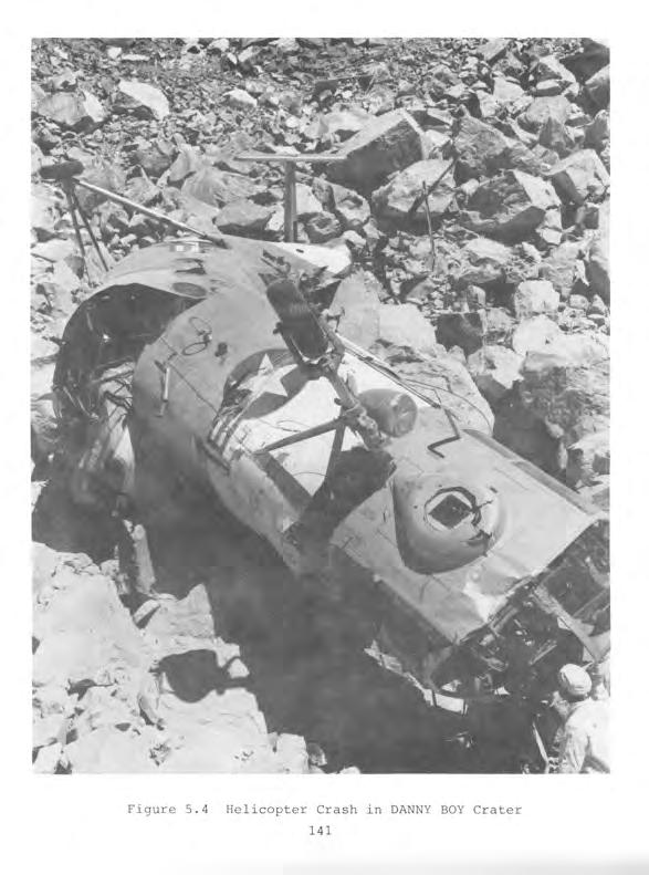
145
Operation DOMINIC II
 Operation DOMINIC II Note: For information related to claims, call the Department of Veterans Affairs (VA) at 800-827-1000 or the Department of Justice (DOJ) at 800-729-7327. For all other information,
Operation HARDTACK II
 Operation HARDTACK II Note: For information related to claims, call the Department of Veterans Affairs (VA) at 800-827-1000 or the Department of Justice (DOJ) at 800-729-7327. For all other information,
Operation BUSTER-JANGLE
 Operation BUSTER-JANGLE Note: For information related to claims, call the Department of Veterans Affairs (VA) at 800-827-1000 or the Department of Justice (DOJ) at 800-729-7327. For all other information,
Operation TUMBLER-SNAPPER
 Operation TUMBLER-SNAPPER Note: For information related to claims, call the Department of Veterans Affairs (VA) at 800-827-1000 or the Department of Justice (DOJ) at 800-729-7327. For all other information,
Operation PLUMBBOB. Historical Background
 Operation PLUMBBOB Note: For information related to claims, call the Department of Veterans Affairs (VA) at 800-827-1000 or the Department of Justice (DOJ) at 800-729-7327. For all other information, call
Projects GNOME and SEDAN The PLOWSHARE Program
 Projects GNOME and SEDAN The PLOWSHARE Program Note: For information related to claims, call the Department of Veterans Affairs (VA) at 800-827-1000 or the Department of Justice (DOJ) at 800-729-7327.
31 AUGUST NOVEMBER 1968
 HAROLD L. BRODE DNA 6322~ OPERATONS CROSSTE AND BOWLNE EVENTS DOOR MST, DORSAL FN, MLK SHAKE, DANA MOON, HUDSON SEAL, AND MNG VASE 31 AUGUST 1967-20 NOVEMBER 1968 Distribution authorized to U.S. Government
Operation UPSHOT-KNOTHOLE
 Operation UPSHOT-KNOTHOLE Note: For information related to claims, call the Department of Veterans Affairs (VA) at 800-827-1000 or the Department of Justice (DOJ) at 800-729-7327. For all other information,
OPERATION TUMBLER-SNAPPER 1952
 , DNA 6019F OPERATION TUMBLER-SNAPPER 1952 United States Atmospheric Nuclear Weapons Tests Nuclear Test Personnel Review Prepared by the Defense Nuclear Agency as Executive Agency for the Department of
OPERATION DOMINIC3I. Shots LITTLE FELLER I[, JOHNIE BOY, SMALL BOY, LITTLE FELLER I 7 JULY-17 JULY 1962
 DNA 6027F OPERATION DOMINIC3I Shots LITTLE FELLER I[, JOHNIE BOY, SMALL BOY, LITTLE FELLER I 7 JULY-17 JULY 1962 " MAY 1 9 18._ I,s A % STATESOt - United States Atmospheric Nuclear Weapons Tests >" Nuclear
OPERATION BUSTER-JANGLE 1951
 DNA 6023F OPERATION BUSTER-JANGLE 1951 United States Atmospheric Nuclear Weapons Tests Nuclear Test Personnel Review Prepared by the Defense Nuclear Agency as Executive Agency for the Department of Defense
SHOTS ABLE, BAKER, CHARLIE, AND DOG. TUMBLER-SNAPPER Series 1 APRIL - 1 MAY 1952
 DNA 6020F SHOTS ABLE, BAKER, CHARLIE, AND DOG The First Tests of the TUMBLER-SNAPPER Series 1 APRIL - 1 MAY 1952 United States Atmospheric Nuclear Weapons Testa Nuclear Test Personnel Review Prepared by
Destroy this report when it is no longer needed. Do not return to sender.
 Destroy this report when it is no longer needed. Do not return to sender. PLEASE NOTIFY THE DEFENSE NUCLEAR AGENCY, ATTN: STTI, WASHINGTON, D.C. 20305, IF YOUR ADDRESS IS INCORRECT, IF YOU WISH TO BE DELETED
EIhIIIIIIIIu. EIIIIIIIIIIIIu
 AD-Ai22 243 SHOTS SUGAR AND UNCLE THE FINAL TESTS OF THE1/ EIhIIIIIIIIu BUSTER-JANGLE SERIES 19 NOVE..(U) JRB ASSOCIATES INC MCLEAN VR J PONTON ET AL. 23 JUN 82 DNA-6825F UNCLASSIFIED DNAeSi-79-C-8473
SHOTS. WHEELER TO MORGAN The Final Eight Tests of the PLUMBBOB Series 6 SEPTEMBER - 7 OCTOBER 1957
 DNA 6007F SHOTS WHEELER TO MORGAN The Final Eight Tests of the PLUMBBOB Series 6 SEPTEMBER - 7 OCTOBER 1957 United States Atmospheric Nuclear Weapons Tests Nuclear Test Personnel Review llili bookbelongs
A Test ~:of the r--l > 31 AUGUST Nuclear Test Persannef Review
 DNA 6004F A Test ~:of the r--l > PLU MBBCB., Series 31 AUGUST 1957 United States Atmospheric N,uclear We!apons Tests Nuclear Test Persannef Review Prepared by the Defense Nucle&Agency as Executive Agency,~._
Joint Electronics Type Designation Automated System
 Army Regulation 70 76 SECNAVINST 2830.1 AFI 60 105 Research, Development, and Acquisition Joint Electronics Type Designation Automated System Headquarters Departments of the Army, the Navy, and the Air
BUSTER-JANGLE OPERATION. 4- Prepared by the Defense Nuclear Agency as Executive Agency DNA 6023F
 DNA 6023F OPERATION BUSTER-JANGLE 1951 United States Atmospheric Nuclear Weapons Tests Nuclear Test Personnel Review 4- Prepared by the Defense Nuclear Agency as Executive Agency - for the Department of
Radiological Consequence Management
 Radiological Consequence Management David Bowman, Ph.D., CHP Consequence Management Program Manager Office of Emergency Response (NA-42) National Nuclear Security Administration U.S. Department of Energy
OPERATBON UPSHOT-KNOTHOLE 1953
 DNA 64F OPERATBON UPSHOTKNOTHOLE 953 United States Atmospheric Nuclear Weapons Tests Nuclear Test Personnel Review Prepared by the Defense Nuclear Agency as Executive Agency for the Department of Defense
Defense Threat Reduction Agency s. Defense Threat Reduction Information Analysis Center
 Defense Threat Reduction Agency s Defense Threat Reduction Information Analysis Center 19 November 2008 Approved for Public Release U.S. Government Work (17 USC 105) Not copyrighted in the U.S. Report
The Army Proponent System
 Army Regulation 5 22 Management The Army Proponent System Headquarters Department of the Army Washington, DC 3 October 1986 UNCLASSIFIED Report Documentation Page Report Date 03 Oct 1986 Report Type N/A
SHOT PRISCILLA A Test of the PLUMBBOB Series 24 JUNE 1957
 DNA 6003F SHOT PRISCILLA A Test of the PLUMBBOB Series 24 JUNE 1957 This is the DASIAC FILE COPY Please DO NOT REMOVE from Reading Area. United States Atmospheric Nuclear Weapons Tests Nuclear Test Personnel
F/6 18/3 SHOT SMOKY, A TEST MAY AS1 P 5 HARRIS, C LOWERY, A G NELSON DNAOOI-7A-C-0311 UNCLASSIFIED JAYCOR DNA-6004F NL
 F/6 18/3 SHOT SMOKY, A TEST 7 AA103 828 JAYCOR ALEXANDRIA VA OF THE PLUMBBOR SERIES, 31 AUGUST 1957.(U) MAY AS1 P 5 HARRIS, C LOWERY, A G NELSON DNAOOI-7A-C-0311 UNCLASSIFIED JAYCOR-2087-79-01 DNA-6004F
GNOME AND SEDAN The PLOWSHARE POgra
 PROJ ECTSNF GNOME AND SEDAN The PLOWSHARE POgra I' jul 6 1983 United States Atmospheric Nuclear Weapons Tests Nuclear Test Personnel Review CL.dis Thi. -docuament has =ben ppoved for puhu'i reeae iand
STATEMENT OF DR. STEPHEN YOUNGER DIRECTOR, DEFENSE THREAT REDUCTION AGENCY BEFORE THE SENATE ARMED SERVICES COMMITTEE
 FOR OFFICIAL USE ONLY UNTIL RELEASED BY THE SENATE ARMED SERVICES COMMITTEE STATEMENT OF DR. STEPHEN YOUNGER DIRECTOR, DEFENSE THREAT REDUCTION AGENCY BEFORE THE SENATE ARMED SERVICES COMMITTEE EMERGING
A Brief Synopsis of Army Contributions to Early Health Physics and Nuclear Engineering
 A Brief Synopsis of Army Contributions to Early Health Physics and Nuclear Engineering Gregory R. Komp, CHP Class of 92 The views presented are those of the speaker and do not necessarily represent the
Guide to the William Geagley Collection on Nuclear Safety
 Guide to the William Geagley Collection on Nuclear Safety This finding aid was created by Lindsay Oden and Sarah Jones on April 27, 2018. Persistent URL for this finding aid: http://n2t.net/ark:/62930/f1n602
SHOTS DIABLO TO FRANKLIN PRIME
 SHOTS DNA 6006F DIABLO TO FRANKLIN PRIME The Mid-Series Tests of the PLUMBBOB Series 15 JULY - 30 AUGUST 1957 United States Atmospheric Nuclear Weapons Tests Nuclear Test Personnel Review Prepared by the
DOE Response to a Nuclear or Radiological Incident. Alan Remick Consequence Management Programs Manager
 DOE Response to a Nuclear or Radiological Incident Alan Remick Consequence Management Programs Manager NA-42 Mission & Authorities Provide a versatile, capable, nuclear or radiological emergency response
COMPLIANCE WITH THIS PUBLICATION IS MANDATORY
 BY ORDER OF THE SECRETARY OF THE AIR FORCE AIR FORCE INSTRUCTION 91-110 13 JANUARY 2015 Safety NUCLEAR SAFETY REVIEW AND LAUNCH APPROVAL FOR SPACE OR MISSILE USE OF RADIOACTIVE MATERIAL AND NUCLEAR SYSTEMS
4677 th DEFENSE SYSTEMS EVALUATION SQUADRON
 4677 th DEFENSE SYSTEMS EVALUATION SQUADRON Evaluation Flight, a Hill AFB tenant organization. 18 Mar 1954 Air Defense Command redesignated its 4677th Radar Evaluation Squadron as the 4677th Defense Systems
SEC J - Appendix G Modifications to Applicable Directives
 DOE O 110.3A DOE O 130.1 DOE M 140.1-1B DOE O 142.1 DOE M 142.2-1, DOE O 142.2A, DOE O 142.3A Conference Management Budget Formulation Interface with the Defense Nuclear Facilities Safety Board Classified
Dr. Mohamed Mughal. Homeland Defense Business Unit U.S. Army Soldier and Biological Chemical Command Department of Defense
 Dr. Mohamed Mughal Homeland Defense Business Unit Department of Defense Telephone: 410-436-4921 Email: mohamed.mughal@sbccom.apgea.army.mil Report Documentation Page Report Date 30Apr2001 Report Type N/A
National Council on Radiation Protection and Measurements Homeland Security Recommendations Related to Nuclear and Radiological Terrorism
 National Council on Radiation Protection and Measurements Homeland Security Recommendations Related to Nuclear and Radiological Terrorism DHS Standards Program Review August 29, 2006 Name - DA Schauer
FEDERAL DEPARTMENTS AND AGENCIES WITH DIRECT INVOLVEMENT IN CT SCANNING
 Appendix VI FEDERAL DEPARTMENTS AND AGENCIES WITH DIRECT INVOLVEMENT IN CT SCANNING Various aspects of CT scanning come under the jurisdiction of different Federal departments and agencies. Many of these
S. ll. To provide for the improvement of the capacity of the Navy to conduct surface warfare operations and activities, and for other purposes.
 TH CONGRESS D SESSION S. ll To provide for the improvement of the capacity of the Navy to conduct surface warfare operations and activities, and for other purposes. IN THE SENATE OF THE UNITED STATES llllllllll
Department of Defense INSTRUCTION
 Department of Defense INSTRUCTION NUMBER 5230.16 October 6, 2015 ATSD(PA) SUBJECT: Nuclear-Radiological Incident Public Affairs (PA) Guidance References: See Enclosure 1 1. PURPOSE. This instruction reissues
FM MILITARY POLICE LEADERS HANDBOOK. (Formerly FM 19-4) HEADQUARTERS, DEPARTMENT OF THE ARMY
 HEADQUARTERS, DEPARTMENT OF THE ARMY") (Formerly FM 19-4) MILITARY POLICE LEADERS HANDBOOK HEADQUARTERS, DEPARTMENT OF THE ARMY DISTRIBUTION RESTRICTION: distribution is unlimited. Approved for public release; (FM 19-4) Field Manual No. 3-19.4
(Formerly FM 19-4) MILITARY POLICE LEADERS HANDBOOK HEADQUARTERS, DEPARTMENT OF THE ARMY DISTRIBUTION RESTRICTION: distribution is unlimited. Approved for public release; (FM 19-4) Field Manual No. 3-19.4
Quality Assurance Specialist (Ammunition Surveillance)
") Army Regulation 702 12 Product Assurance Quality Assurance Specialist (Ammunition Surveillance) Headquarters Department of the Army Washington, DC 20 March 2002 UNCLASSIFIED Report Documentation Page Report
Army Regulation 702 12 Product Assurance Quality Assurance Specialist (Ammunition Surveillance) Headquarters Department of the Army Washington, DC 20 March 2002 UNCLASSIFIED Report Documentation Page Report
U.S. ARMY EXPLOSIVES SAFETY TEST MANAGEMENT PROGRAM
 U.S. ARMY EXPLOSIVES SAFETY TEST MANAGEMENT PROGRAM William P. Yutmeyer Kenyon L. Williams U.S. Army Technical Center for Explosives Safety Savanna, IL ABSTRACT This paper presents the U.S. Army Technical
FIG 18/3. S EP A C MAAG J PoNToN ONAD O1-79-C-0473 UNCLSSIFED ONA-600F N
 FIG 18/3 SHOTS OIAB 0 To AD-AIM 683 J RB ASSOCIATES INC FRANKLIN MCLEAN PRIME, VA THE mro-series TESTS OF THE PLU--ETC(U) S EP A C MAAG J PoNToN ONAD O1-79-C-0473 UNCLSSIFED ONA-600F N 00 - AI UNCLASSIFIED
Unexploded Ordnance (UXO)
") BRAC Environmental Fact Sheet SPRING 1999 OFFICE OF THE DEPUTY UNDER SECRETARY OF DEFENSE (ENVIRONMENTAL SECURITY) Unexploded Ordnance (UXO) The Department of Defense (DoD) defines military munitions/explosive
BRAC Environmental Fact Sheet SPRING 1999 OFFICE OF THE DEPUTY UNDER SECRETARY OF DEFENSE (ENVIRONMENTAL SECURITY) Unexploded Ordnance (UXO) The Department of Defense (DoD) defines military munitions/explosive
COMPLIANCE WITH THIS PUBLICATION IS MANDATORY
 BY ORDER OF THE SECRETARY OF THE AIR FORCE AIR FORCE INSTRUCTION 91-117 9 SEPTEMBER 2009 Safety SAFETY RULES FOR THEAIRBORNE LAUNCH CONTROL SYSTEM COMPLIANCE WITH THIS PUBLICATION IS MANDATORY ACCESSIBILITY:
U.S. Army Command and Control Support Agency
 Army Regulation 10 47 Organization and Functions U.S. Army Command and Control Support Agency Headquarters Department of the Army Washington, DC 22 February 1985 Unclassified Report Documentation Page
SHOT HOOD. A Test of the PLUMBBOB Series DNA 6002F. United States Atmospheric Nuclear Weapons Tests. Nuclear Test Personnel Review
 DNA 6002F SHOT HOOD c A Test of the PLUMBBOB Series United States Atmospheric Nuclear Weapons Tests Nuclear Test Personnel Review Prepared by the Defense Nuclear Agency as Executive Agency for the Department
Edited extract from: Department of the Army Historical Summary, FY 1979 (Washington, D.C.: U.S. Army Center of Military History, 1982, pp
 Edited extract from: Department of the Army Historical Summary, FY 1979 (Washington, D.C.: U.S. Army Center of Military History, 1982, pp. 179-186.) Ballistic Missile Defense The Ballistic Missile Defense
DoD Countermine and Improvised Explosive Device Defeat Systems Contracts for the Vehicle Optics Sensor System
 Report No. DODIG-2012-005 October 28, 2011 DoD Countermine and Improvised Explosive Device Defeat Systems Contracts for the Vehicle Optics Sensor System Report Documentation Page Form Approved OMB No.
Public Lands Committee Briefing
 Hawthorne Army Depot Public Lands Committee Briefing LTC John Summers Commander DSN: 830-7001 Email: johnny.summers@us.army.mil Hawthorne Will Always Deliver EXHIBIT C - LANDS Meeting Date: 03-24-06 Document
POLICY AND GLOBAL AFFAIRS The National Academies Press Washington, DC March 30, /30/2012 1
 POLICY AND GLOBAL AFFAIRS The National Academies Press Washington, DC www.nap.edu March 30, 2012 3/30/2012 1 The Study Committee ELLEN D. WILLIAMS, Chair, BP MARVIN L. ADAMS, Texas A&M University LINTON
Munitions Support for Joint Operations
 Army Regulation 700 100 MCO 8012.1 Logistics Munitions Support for Joint Operations Headquarters Departments of the Army, and the Marines Washington, DC 26 March 2014 UNCLASSIFIED SUMMARY of CHANGE AR
COMPLIANCE WITH THIS PUBLICATION IS MANDATORY
 BY ORDER OF THE SECRETARY OF THE AIR FORCE AIR FORCE POLICY DIRECTIVE 40-2 12 JANUARY 2015 Aerospace Medicine RADIOACTIVE MATERIALS (NON-NUCLEAR WEAPONS) COMPLIANCE WITH THIS PUBLICATION IS MANDATORY ACCESSIBILITY:
Department of Defense INSTRUCTION
 Department of Defense INSTRUCTION NUMBER 5230.27 November 18, 2016 Incorporating Change 1, September 15, 2017 USD(AT&L) SUBJECT: Presentation of DoD-Related Scientific and Technical Papers at Meetings
REGULATORY DOCUMENTS. The main classes of regulatory documents developed by the CNSC are:
 Canadian Nuclear Safety Commission Commission canadienne de sûreté nucléaire REGULATORY GUIDE Emergency Planning at Class I Nuclear Facilities and Uranium Mines and Mills G-225 August 2001 REGULATORY DOCUMENTS
STOCKTON POLICE DEPARTMENT GENERAL ORDER DOWNED AIRPLANES SUBJECT
 STOCKTON POLICE DEPARTMENT GENERAL ORDER DOWNED AIRPLANES SUBJECT DATE: March 1, 2005 NO: FROM: CHIEF ERIC JONES TO: ALL PERSONNEL INDEX: Airplane Crashes Procedure for Plane Crashes Landing of Aircraft
Naval Support Facility. Indian Head. Supporting Our Military and Our Nation INSTALLATION OVERVIEW JULY 2010 APPROVED FOR PUBLIC RELEASE
 Naval Support Facility Indian Head Supporting Our Military and Our Nation INSTALLATION OVERVIEW JULY 2010 APPROVED FOR PUBLIC RELEASE Indian Head A Unique Naval Heritage Indian Head Naval Proving Ground
Information Technology
 May 7, 2002 Information Technology Defense Hotline Allegations on the Procurement of a Facilities Maintenance Management System (D-2002-086) Department of Defense Office of the Inspector General Quality
The 1969 ACDA Study on Warhead Dismantlement Frank von Hippel
 OCCASIONAL REPORT The 1969 ACDA Study on Warhead Dismantlement Frank von Hippel In response to a Freedom of Information request, the US Arms Control and Disarmament Agency (ACDA) has just unearthed from
Security of Unclassified Army Property (Sensitive and Nonsensitive)
") Army Regulation 190 51 Military Police Security of Unclassified Army Property (Sensitive and Nonsensitive) Headquarters Department of the Army Washington, DC 30 September 1993 UNCLASSIFIED SUMMARY of CHANGE
Army Regulation 190 51 Military Police Security of Unclassified Army Property (Sensitive and Nonsensitive) Headquarters Department of the Army Washington, DC 30 September 1993 UNCLASSIFIED SUMMARY of CHANGE
ASSESSMENT OF THE SAFETY OF US NUCLEAR WEAPONS AND RELATED NUCLEAR TEST REQUIREMENTS
 OCCASIONAL REPORT ASSESSMENT OF THE SAFETY OF US NUCLEAR WEAPONS AND RELATED NUCLEAR TEST REQUIREMENTS Ray E. Kidder a This brief report was prepared in response to a letter of 17 July 1990 by Honorable
or.t Office of the Inspector General Department of Defense DISTRIBUTION STATEMENTA Approved for Public Release Distribution Unlimited
 t or.t 19990818 181 YEAR 2000 COMPLIANCE OF THE STANDOFF LAND ATTACK MISSILE Report No. 99-157 May 14, 1999 DTIO QUr~ Office of the Inspector General Department of Defense DISTRIBUTION STATEMENTA Approved
THE VIEWS AND ISSUES OF AMERICA S ATOMIC VETERANS N-001
 THE VIEWS AND ISSUES OF AMERICA S ATOMIC VETERANS N-001 TRINITY SITE - NEW MEXICO THE FIRST ATOMIC BOMB TEST JULY 16, 1945 ATOMIC BOMB DROPPED OVER HIROSHIMA, JAPAN AUGUST 6, 1945 ATOMIC BOMB DROPPED OVER
CWA 2.5 The President s Daily Bulletin (Nuclear Arms Race) Timeline
 Timeline") Timeline 1942 US begins work on the Manhattan Project, a research and development effort that produced the first atomic bombs. As the project moves forward, Soviet spies secretly report on its developments
Timeline 1942 US begins work on the Manhattan Project, a research and development effort that produced the first atomic bombs. As the project moves forward, Soviet spies secretly report on its developments
MAINTAINING GLOBAL VIGILANCE
 SU PR A E T ULTR A MAINTAINING GLOBAL The National Reconnaissance Office (NRO) is a joint Department of Defense (DoD)-Intelligence Community (IC) organization responsible for developing, launching, and
RESPONDING TO COMPOSITE FIRES: FIRST RESPONDER TRAINING MODULE
 AFRL-ML-TY-TP-2005-4529 RESPONDING TO COMPOSITE FIRES: FIRST RESPONDER TRAINING MODULE Jennifer Kiel, Douglas Dierdorf Applied Research Associates P.O. Box 40128 Tyndall AFB, FL 32403 D. McBride, T. Harmon
Acquisition. Air Force Procurement of 60K Tunner Cargo Loader Contractor Logistics Support (D ) March 3, 2006
 March 3, 2006") March 3, 2006 Acquisition Air Force Procurement of 60K Tunner Cargo Loader Contractor Logistics Support (D-2006-059) Department of Defense Office of Inspector General Quality Integrity Accountability Report
March 3, 2006 Acquisition Air Force Procurement of 60K Tunner Cargo Loader Contractor Logistics Support (D-2006-059) Department of Defense Office of Inspector General Quality Integrity Accountability Report
Remote Sensor Operations
 MCRP 2-24B Remote Sensor Operations U.S. Marine Corps PCN 144 000153 00 MCCDC (C 42) 13 Jul 2004 E R R A T U M to MCRP 2-24B REMOTE SENSOR OPERATIONS 1. Change the publication short title to read MCRP
Report Documentation Page
 Report Documentation Page Form Approved OMB No. 0704-0188 Public reporting burden for the collection of information is estimated to average 1 hour per response, including the time for reviewing instructions,
i its CLE4 5 MAY 1955 SHOT TEAPOT Series A Test of the APPLE 2 DNA 6012F
 DNA 6012F SHOT APPLE 2 A Test of the TEAPOT Series 5 MAY 1955 i its CLE4 United States Atmospheric Nuclear Weapons Tests. Nuclear Test Personnel Review Prepared by the Defense Nuclear Agency as Executive
AIR FORCE CONTRACT CONSTRUCTION
 Army Regulation 415 11 BUDOCKSINST 11013-14 AFR 88-3 Construction AIR FORCE CONTRACT CONSTRUCTION Headquarters Departments of the Army, the Navy, and the Air Force Washington, DC 29 March 55 Unclassified
Low Altitude Air Defense (LAAD) Gunner's Handbook
 Gunner's Handbook") MCRP 3-25.10A Low Altitude Air Defense (LAAD) Gunner's Handbook U.S. Marine Corps PCN 144 000092 00 To Our Readers Changes: Readers of this publication are encouraged to submit suggestions and changes
MCRP 3-25.10A Low Altitude Air Defense (LAAD) Gunner's Handbook U.S. Marine Corps PCN 144 000092 00 To Our Readers Changes: Readers of this publication are encouraged to submit suggestions and changes
C.A. Nelson, K.A. Firestone, G.R. Papazian, D.P. Serpa, J.H. Halstead, V.C. Lew, D.C. Conrad and T. Hunsaker
 UCRL-JC-127308 PREPRINT Integrated Safety Management Approach for the Approval and Conduct of Subcritical Experiments (SCE) for the Science-Based Nuclear Stockpile Stewardship Program C.A. Nelson, K.A.
THE CTBT AND ON-SITE INSPECTIONS
 THE CTBT AND ON-SITE INSPECTIONS The Preparatory Commission for the Comprehensive Nuclear-Test-Ban Treaty Organization is mandated to carry out the necessary preparations for the effective implementation
mm*. «Stag GAO BALLISTIC MISSILE DEFENSE Information on Theater High Altitude Area Defense (THAAD) and Other Theater Missile Defense Systems 1150%
 and Other Theater Missile Defense Systems 1150%") GAO United States General Accounting Office Testimony Before the Committee on Foreign Relations, U.S. Senate For Release on Delivery Expected at 10:00 a.m.,edt Tuesday May 3,1994 BALLISTIC MISSILE DEFENSE
GAO United States General Accounting Office Testimony Before the Committee on Foreign Relations, U.S. Senate For Release on Delivery Expected at 10:00 a.m.,edt Tuesday May 3,1994 BALLISTIC MISSILE DEFENSE
Department of Defense DIRECTIVE. SUBJECT: Single Manager Responsibility for Military Explosive Ordnance Disposal Technology and Training (EODT&T)
") Department of Defense DIRECTIVE NUMBER 5160.62 June 3, 2011 Incorporating Change 1, May 15, 2017 SUBJECT: Single Manager Responsibility for Military Explosive Ordnance Disposal Technology and Training
Department of Defense DIRECTIVE NUMBER 5160.62 June 3, 2011 Incorporating Change 1, May 15, 2017 SUBJECT: Single Manager Responsibility for Military Explosive Ordnance Disposal Technology and Training
UNCLASSIFIED FY 2016 OCO. FY 2016 Base
 Exhibit R-2, RDT&E Budget Item Justification: PB 2016 Air Force : February 2015 COST ($ in Millions) FY 2017 FY 2018 FY 2019 FY 2020 To Program Element 65.370 76.553 59.826 142.551-142.551 190.973 180.205
Department of Defense DIRECTIVE
 Department of Defense DIRECTIVE NUMBER 3150.08 January 20, 2010 USD(AT&L) SUBJECT: DoD Response to Nuclear and Radiological Incidents References: See Enclosure 1 1. PURPOSE. This Directive reissues DoD
Department of Defense DIRECTIVE
 Department of Defense DIRECTIVE NUMBER 6490.02E February 8, 2012 USD(P&R) SUBJECT: Comprehensive Health Surveillance References: See Enclosure 1 1. PURPOSE. This Directive: a. Reissues DoD Directive (DoDD)
LESSON 5: THE U.S. AIR FORCE
 LESSON 5: THE U.S. AIR FORCE avionics parity payload proliferation stealth INTRODUCTION The U.S. Air Force exemplifies the dominant role of air and space power in meeting this nation s security needs across
Department of Defense DIRECTIVE
 Department of Defense DIRECTIVE NUMBER 1300.22 October 30, 2015 USD(P&R) SUBJECT: Mortuary Affairs Policy References: See Enclosure 1 1. PURPOSE. This directive: a. Reissues DoD Directive (DoDD) 1300.22E
Support for FLIP/ORB. Fred H. Fisher. Final Report to the Office of Naval Research Contract N D-0142 (DO#26)
") Marine Physical Laboratory Support for FLIP/ORB Fred H. Fisher Final Report to the Office of Naval Research Contract N00014-89-D-0142 (DO#26) MW15 021 MPL-U-18/95 March 1996 Approved for public release;
Marine Physical Laboratory Support for FLIP/ORB Fred H. Fisher Final Report to the Office of Naval Research Contract N00014-89-D-0142 (DO#26) MW15 021 MPL-U-18/95 March 1996 Approved for public release;
Preparing to Occupy. Brigade Support Area. and Defend the. By Capt. Shayne D. Heap and Lt. Col. Brent Coryell
 Preparing to Occupy and Defend the Brigade Support Area By Capt. Shayne D. Heap and Lt. Col. Brent Coryell A Soldier from 123rd Brigade Support Battalion, 3rd Brigade Combat Team, 1st Armored Division,
Human Capital. DoD Compliance With the Uniformed and Overseas Citizens Absentee Voting Act (D ) March 31, 2003
 March 31, 2003") March 31, 2003 Human Capital DoD Compliance With the Uniformed and Overseas Citizens Absentee Voting Act (D-2003-072) Department of Defense Office of the Inspector General Quality Integrity Accountability
March 31, 2003 Human Capital DoD Compliance With the Uniformed and Overseas Citizens Absentee Voting Act (D-2003-072) Department of Defense Office of the Inspector General Quality Integrity Accountability
COMPLIANCE WITH THIS PUBLICATION IS MANDATORY
 BY ORDER OF THE COMMANDER MACDILL AIR FORCE BASE MACDILL AIR FORCE BASE INSTRUCTION 48-100 23 JANUARY 2015 Aerospace Medicine INSTALLATION RADIATION SAFETY PROGRAM COMPLIANCE WITH THIS PUBLICATION IS MANDATORY
PROJECT 1947 REPORT BY THE DIRECTOR OF INTELLIGENCE, USAF. to the JOINT INTELLIGENCE COMMITTEE UNIDENTIFIED AERIAL OBJECTS THE PROBLEM
 PROJECT 1947 COPY NO. 5 J.I.C. REPORT BY THE DIRECTOR OF INTELLIGENCE, USAF to the JOINT INTELLIGENCE COMMITTEE on UNIDENTIFIED AERIAL OBJECTS THE PROBLEM 22nd of December 1947, in a memorandum, "Analysis
Department of Defense DIRECTIVE
 Department of Defense DIRECTIVE NUMBER 5040.4 August 13, 2002 Certified Current as of November 21, 2003 SUBJECT: Joint Combat Camera (COMCAM) Program ASD(PA) References: (a) DoD Directive 5040.4, "Joint
Subj: NUCLEAR SURVIVABILITY POLICY FOR NAVY AND MARINE CORPS SYSTEMS
 DEPARTMENT OF THE NAVY OFFICE OF THE CHIEF OF NAVAL OPERATIONS 2000 NAVY PENTAGON WASHINGTON, DC 20350-2000 OPNAVINST 3401.3B N9 OPNAV INSTRUCTION 3401.3B From: Chief of Naval Operations Subj: NUCLEAR
Laughlin. Air Force Base. Economic Impact Statement FY16
 Laughlin Air Force Base Economic Impact Statement FY16 Graduate the World s Best Pilots Deploy Mission-Ready Warriors Develop Professional, Resilient and Innovative Airmen Table of Contents Foreword 3
Military Working Dog Program
 Department of the Army Pamphlet 190 12 Military Police Military Working Dog Program Headquarters Department of the Army Washington, DC 30 September 1993 UNCLASSIFIED SUMMARY of CHANGE DA PAM 190 12 Military
Army Use of United Service Organizations, Inc., Services
 Army Regulation 930 1 Service Organizations Army Use of United Service Organizations, Inc., Services Headquarters Department of the Army Washington, DC 16 July 2004 UNCLASSIFIED SUMMARY of CHANGE AR 930
H. R IN THE HOUSE OF REPRESENTATIVES
 I TH CONGRESS 1ST SESSION H. R. To preserve the cooperative, peaceful uses of space for the benefit of all humankind by permanently prohibiting the basing of weapons in space by the United States, and
Training and Evaluation Outline Report
 Training and Evaluation Outline Report Task Number: 01-6-0416 Task Title: Conduct Aviation Missions as part of an Area Defense Supporting Reference(s): Step Number Reference ID Reference Name Required
SERIES 1300 DIRECTOR, DEFENSE RESEARCH AND ENGINEERING (DDR&E) DEFENSE RESEARCH AND ENGINEERING (NC )
 DEFENSE RESEARCH AND ENGINEERING (NC )") SERIES 1300 DIRECTOR, DEFENSE RESEARCH AND ENGINEERING (DDR&E) 1300. DEFENSE RESEARCH AND ENGINEERING (NC1-330-77-15) These files relate to research and engineering (R&E) and pertain to: Scientific and
SERIES 1300 DIRECTOR, DEFENSE RESEARCH AND ENGINEERING (DDR&E) 1300. DEFENSE RESEARCH AND ENGINEERING (NC1-330-77-15) These files relate to research and engineering (R&E) and pertain to: Scientific and
Review of Defense Contract Management Agency Support of the C-130J Aircraft Program
 Report No. D-2009-074 June 12, 2009 Review of Defense Contract Management Agency Support of the C-130J Aircraft Program Special Warning: This document contains information provided as a nonaudit service
Yucca Mountain and Interim Storage Proposed Appropriation Language
 Proposed Appropriation Language NUCLEAR WASTE DISPOSAL For Department of Energy expenses necessary for nuclear waste disposal activities to carry out the purposes of the Nuclear Waste Policy Act of 1982,
National Nuclear Security Administration
 National Nuclear Security Administration Presentation to Workshop on Risk Assessment and Safety Decision-Making Under Uncertainly By Jim McConnell, Assistant Deputy Administrator for Nuclear Safety, Nuclear
The Military Health System
 The Military Health System How Might It Be Reorganized? Since the end of World War II, the issue of whether to create a unified military health system has arisen repeatedly. Some observers have suggested
DOE/NNSA Radiological Assistance Program (RAP) Capabilities Overview. Hans Oldewage Training and Outreach Coordinator RAP Region 4 (505)
 Capabilities Overview. Hans Oldewage Training and Outreach Coordinator RAP Region 4 (505)") DOE/NNSA Radiological Assistance Program (RAP) Capabilities Overview Hans Oldewage Training and Outreach Coordinator RAP Region 4 (505) 845-7728 1 DOE/NNSA Mission Ensure capabilities are in place to provide
DOE/NNSA Radiological Assistance Program (RAP) Capabilities Overview Hans Oldewage Training and Outreach Coordinator RAP Region 4 (505) 845-7728 1 DOE/NNSA Mission Ensure capabilities are in place to provide
CHAPTER 20 SUMMARY OF SPECIALIZED CAPABILITIES
 DoD 51 OO.52-M CHAPTER 20 SUMMARY OF SPECIALIZED CAPABILITIES 20-1 GENERAL Numerous units and organizations with specialized capabilities are discussed throughout this document. This chapter summarizes
Department of Defense INSTRUCTION
 Department of Defense INSTRUCTION NUMBER 5230.27 October 6, 1987 USD(A) SUBJECT: Presentation of DoD-Related Scientific and Technical Papers at Meetings References: (a) DoD Directive 3200.12, "DoD Scientific