SHIP-TO-SHORE MOVEMENT NTTP M/MCWP
|
|
|
- Clemence Douglas
- 6 years ago
- Views:
Transcription
1 U.S. NAVY NTTP M U.S. MARINE CORPS SHIP-TO-SHORE MOVEMENT NTTP M/ EDITION MAY 2007 DEPARTMENT OF THE NAVY OFFICE OF THE CHIEF OF NAVAL OPERATIONS DISTRIBUTION AUTHORIZED TO THE DEPARTMENT OF DEFENSE AND U.S. DOD CONTRACTORS ONLY FOR OPERATIONAL USE TO PROTECT TECHNICAL DATA OR INFORMATION FROM AUTOMATIC DISSEMINATION. THIS DETERMINATION WAS MADE MAY OTHER REQUESTS SHALL BE REFERRED TO NAVY WARFARE DEVELOPMENT COMMAND, 686 CUSHING ROAD, NEWPORT, RI OR MARINE CORPS COMBAT DEVELOPMENT COMMAND, 3300 RUSSELL ROAD, QUANTICO, VA PRIMARY REVIEW AUTHORITY: SURFACE WARFARE DEVELOPMENT GROUP URGENT CHANGE/ERRATUM RECORD NUMBER DATE ENTERED BY MARINE CORPS DISTRIBUTION: PCN LP MAY 2007
2 INTENTIONALLY BLANK MAY
3
4 INTENTIONALLY BLANK MAY
5 May 2007 PUBLICATION NOTICE ROUTING 1. NTTP M/, Ship-to-Shore Movement, is available in the Navy Warfare Library. It is effective upon receipt. 2. NTTP M/ discusses the doctrine, command relationships, tactics, techniques, and procedures (TTP) for planning and executing ship-to-shore movement during amphibious operations. It revises and updates the legacy publication (NWP /FMFM 1-8) and incorporates and expands on joint doctrine contained in JP 3-02, Joint Doctrine for Amphibious Operations, and other relevant publications and documents. It provides the detail required by amphibious task force (ATF) and landing force (LF) commanders and staffs to plan and conduct amphibious operations, specifically the ship-to-shore movement of any size LF. Navy Warfare Library Custodian Navy warfare library publications must be made readily available to all users and other interested personnel within the U.S. Navy. Classified Navy warfare publications are to be treated in the same manner as other classified information. Note to Navy Warfare Library Custodian: This notice should be duplicated for routing to cognizant personnel to keep them informed of changes to this publication. 5 MAY 2007
6 INTENTIONALLY BLANK MAY
7 CONTENTS Page. No. EXECUTIVE SUMMARY EX.1 EX.2 EX.3 INTRODUCTION... EX-1 PUBLICATION ORGANIZATION... EX-1 TRAINING AID... EX-3 CHAPTER 1 OVERVIEW 1.1 PURPOSE AMPHIBIOUS OPERATIONS BACKGROUND AND OVERVIEW Characteristics of Amphibious Operations Types of Amphibious Operations SHIP-TO-SHORE MOVEMENT CONCEPT LANDING MEANS Amphibious Ships Casualty Receiving and Treatment Ship Military Sealift Command Military Sealift Command Ships Vertical Assault Aircraft Landing Craft Amphibious Assault Vehicles Expeditionary Fighting Vehicle Special Purpose Craft Miscellaneous Vehicles and Support Components CHAPTER 2 ORGANIZATION AND COMMAND 2.1 PURPOSE ORGANIZATION Small-Scale Amphibious Operations Medium- to Large-Scale Amphibious Operations Ship-to-Shore Movement Control AMPHIBIOUS FORCE Amphibious Task Force MAY 2007
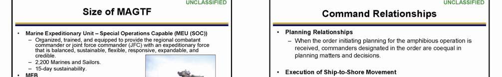
8 2.3.2 Landing Force Marine Expeditionary Force Marine Expeditionary Brigade Marine Expeditionary Unit (Special Operations Capable) Special Purpose Marine Air-Ground Task Force Marine Air-Ground Task Force Movement COMMAND RELATIONSHIPS Amphibious Task Force and Landing Force Commander Command Relationships Relationship Between the Ship's Commanding Officer and the Commanding Officer of Troops Relationship Between the Ship's Commanding Officer and Embarked Aircraft Units Command of the Landing Force Support Party Relationship Between the Amphibious Task Force Surgeon and Landing Force Surgeon CHAPTER 3 PLANNING Page. No. 3.1 PURPOSE BACKGROUND PLANNING PROCESS Tenets of the Marine Corps Planning Process Planning Methods Six-Step Planning Process Landing Serials Troop and Equipment Movement Categories PREPARATION AND PROMULGATION OF KEY DOCUMENTS Documents Prepared by the Navy Documents Prepared by the Landing Force ORGANIZATION OF THE SEA OPERATING AREAS Ocean Operating Areas Sea Areas in the Landing Area ORGANIZATION OF THE BEACH AND INLAND AREAS Combat Service Support Area Beach Support Area Landing Zone Support Area MAY
9 3.6.4 Helicopter Inland Areas Landing Craft Air Cushion Inland Areas Forward Arming and Refueling Point CHAPTER 4 CONDUCTING SURFACEBORNE SHIP-TO-SHORE MOVEMENT 4.1 PURPOSE Page. No. 4.2 BACKGROUND Final Preparations and Approach PLANNING CONSIDERATIONS AND DECISIONS Planning Considerations Planning Decisions Embarkation Flexibility Oceanographic Considerations Mine Countermeasures and Mine Warfare Considerations Mine Countermeasures Techniques and Equipment Considerations Supporting Amphibious Operations Advance Force Operations Preassault/Preaction Operations Prelanding Operations In-Stride Operations Landing Craft and Amphibious Vehicle Considerations and Support Requirements EXECUTION Pre-H-Hour Transfers Surfaceborne Ship-to-Shore Movement Control Organization Control Areas Debarkation Dispatching Scheduled Waves to the Beach Surfaceborne Ship-to-Shore Movement Control Beaching, Retraction, and Return COMMUNICATIONS Control Ship Coordination Net Primary Control Net Beach Boat Control (Alfa Net) Beach Boat Operations (Bravo Net) Landing Craft Air Cushion Communications Landing Force Support Party Command Net Landing Force Support Party Control Net Landing Force Combat Service Support Net MAY 2007
10 4.5.9 Medical Regulating Net CHAPTER 5 CONDUCTING AIRBORNE SHIP-TO-SHORE MOVEMENT 5.1 PURPOSE Page. No. 5.2 BACKGROUND Helicopter Employment Helicopter Capabilities and Limitations Tactical Organization PLANNING CONSIDERATIONS Helicopter Employment Considerations Helicopter Support Requirements AVIATION COMMAND AND CONTROL DURING SHIP-TO-SHORE MOVEMENT Amphibious Task Force Air Control Tactical Air Officer Tactical Air Control Center Watch Officer Amphibious Task Force Tactical Air Control Center Helicopter Coordination Section Helicopter Transport Group/Unit Commander Amphibious Air Tactical Control Center Helicopter Logistic Support Center Tactical-Logistical Group Transitioning Marine Air-Ground Task Force Aviation Command and Control Ashore Direct Air Support Center Airborne Terminal Control Agencies Landing Zone Guidance and Control COMMAND RELATIONSHIPS Relationship Between the Ship's Commanding Officer and an Embarked Helicopter Unit EXECUTION Embarking in Aircraft Troop and Equipment Categories Operating Areas, Routes, and Points Helicopterborne Operations With Control Afloat Downed Aircrew and Aircraft Recovery Operations Sequence of Events for Helicopter Tactical or Combat Service Support Request From a Helicopterborne Unit MAY
11 5.6.7 Sequence of Events for Helicopter Tactical or Combat Service Support Request From a Surfaceborne Unit Helicopterborne Operations With Control Ashore DELEGATION OF AUTHORITY Airborne Control of Vertical Assault Aircraft Shifting From Primary to Alternate Landing Zones Changing Approach and Retirement Routes Changing the Landing Sequence AIRCRAFT CONTROL COMMUNICATIONS Communications Planning Helicopterborne Command, Control, and Coordination Nets Helicopter Support Team Nets Landing Force Support Party Nets APPENDIX A LANDING CRAFT AND AMPHIBIOUS VEHICLE FORMATIONS AND CONTROL SIGNALS A.1 LANDING CRAFT AND AMPHIBIOUS VEHICLE FORMATIONS... A-1 A.1.1 Order of Landing Craft in Formation... A-1 A.2 CONTROL SIGNALS... A-1 APPENDIX B IDENTIFICATION FLAGS, INSIGNIA, MARKERS, LIGHTS, AND SIGNALS B.1 STANDARD IDENTIFICATION... B-1 B.1.1 Flags and Insignia... B-1 B.1.2 Beach, Unloading Point, and Oceanographic Markers... B-1 B.1.3 Cargo Identification... B-2 B.1.4 Beach, Unloading Point, and Oceanographic Lights... B-2 B.1.5 Night and Reduced Visibility Identification Lights for Amphibious Vehicles and Displacement Landing Craft... B-2 B.1.6 Line of Departure Dispatching Signals... B-2 B.1.7 Beaching Signals... B-2 B.1.8 Visual Emergency Signals... B-2 B.2 LANDING CRAFT AIR CUSHION LIGHTS... B-3 APPENDIX C LANDING CRAFT AND AMPHIBIOUS VEHICLE CONTROL PROCEDURES Page. No. C.1 GENERAL... C-1 C.2 PURPOSE... C-1 11 MAY 2007
12 C.3 LANDING CRAFT CONTROL PROCEDURES... C-1 C.3.1 Positive Control... C-1 C.3.2 Advisory Control... C-2 C.3.3 Independent Control... C-2 C.4 GRID CONSTRUCTION... C-2 C.4.1 Wave Control... C-4 C.4.2 Visual Communications Procedures and Communications Circuits... C-5 C.4.3 Visual Procedures for Transmitting Grid Positions... C-8 C.5 ALTERNATE LANDING CRAFT CONTROL PLOTTING PROCEDURES... C-8 C.5.1 Global Positioning System Craft Control... C-9 APPENDIX D SALVAGE OPERATIONS D.1 MISSION... D-1 D.2 ORGANIZATION... D-1 D.3 SALVAGE ASSETS... D-1 D.3.1 Salvage Teams... D-2 D.3.2 Supplementary Salvage Equipment... D-2 D.4 AFLOAT SALVAGE OPERATIONS... D-2 D.4.1 Salvage Procedures... D-2 D.5 LANDING CRAFT AIR CUSHION SALVAGE OPERATIONS... D-7 D.5.1 Seaward of the Surf Zone... D-7 D.5.2 Inland of the Surf Zone... D-8 APPENDIX E RESPONSIBILITIES FOR LOADING, STOWING, AND OFFLOADING LANDING FORCE EQUIPMENT E.1 SCOPE... E-1 E.1.1 Personnel... E-1 E.1.2 Materiel... E-2 APPENDIX F THE TACTICAL-LOGISTICAL GROUP Page. No. F.1 FUNCTION... F-1 F.2 BACKGROUND... F-1 F.2.1 Navy and Landing Force Organizations... F-1 MAY
13 F.3 TACTICAL-LOGISTICAL DETACHMENT COMMON FUNCTIONS... F-2 F.4 ORGANIZATION... F-3 F.4.1 Transitioning From a Tactical to Combat Service Support Focus... F-3 F.4.2 Tactical-Logistical Group Organizational Considerations... F-4 F.4.3 Landing Force Tactical-Logistical Detachment... F-4 F.4.4 Ground Combat Element Tactical-Logistical Detachment... F-5 F.4.5 Surfaceborne Regimental Landing Team Tactical-Logistical Detachment... F-5 F.4.6 Helicopterborne Regimental Landing Team Tactical-Logistical Detachment... F-6 F.5 COMMUNICATIONS... F-7 F.5.1 Landing Force Tactical Net... F-7 F.5.2 Supported Unit Tactical Net... F-7 F.5.3 Helicopterborne Unit Command Net... F-7 F.5.4 Helicopter Support Team Control Net... F-7 F.5.5 Landing Force Support Party Command Net... F-7 F.5.6 Landing Force Support Party Control Net... F-8 F.6 REPORTS... F-8 APPENDIX G LANDING FORCE SUPPORT PARTY G.1 GENERAL... G-1 G.2 PURPOSE... G-1 G.3 LANDING FORCE ELEMENT FUNCTIONS... G-1 G.3.1 Command and Control... G-1 G.3.2 Beach Support Area Development... G-2 G.3.3 Beach Throughput... G-2 G.3.4 Support for Helicopterborne Units... G-2 G.3.5 Other Functions... G-3 G.4 NAVY ELEMENT FUNCTIONS... G-3 G.5 LANDING FORCE SUPPORT PARTY ORGANIZATION... G-3 G.5.1 Landing Force Support Party Headquarters... G-4 G.5.2 Shore Party Group... G-5 G.5.3 Beach Party Group... G-9 G.5.4 Landing Force Support Party Special Attachments... G-14 G.5.5 Helicopter Support Team... G-14 G.6 POST-LANDING FORCE SUPPORT PARTY OPERATIONS... G-14 G.6.1 Aviation Combat Element and Naval Construction Regiment Organization... G-14 Page No. 13 MAY 2007
14 G.6.2 Beach Party and Naval Beach Group... G-15 G.7 PLANNING... G-15 G.7.1 Landing Force Support Party Missions and Tasks... G-15 G.7.2 Landing Force Support Party Concept for Support and Organization for Combat... G-15 G.7.3 Landing Force Support Party Operation Plan... G-15 G.8 COMMUNICATIONS... G-15 G.8.1 Landing Force Support Party Command Net... G-16 G.8.2 Landing Force Support Party Control Net... G-16 G.8.3 Helicopter Request Net... G-16 G.8.4 Helicopter Support Team Control Net... G-16 G.8.5 Supported Unit Tactical Net... G-16 APPENDIX H THE HELICOPTER SUPPORT TEAM H.1 PURPOSE... H-1 H.2 FUNDAMENTALS... H-1 H.2.1 Helicopterborne Operations... H-1 H.2.2 Planned Combat Service Support Buildup... H-2 H.3 HELICOPTER SUPPORT TEAM ORGANIZATION AND RESPONSIBILITIES... H-3 H.3.1 Helicopter Support Team Organization... H-3 H.3.2 Helicopter Support Team Responsibilities... H-5 H.4 HELICOPTER SUPPORT TEAM OPERATIONS... H-6 H.4.1 Embarkation... H-6 H.4.2 Organization for Landing... H-6 H.4.3 Operations Ashore... H-6 H.4.4 Termination of Helicopter Support Team Operations... H-7 APPENDIX I TRANSFORMATIONAL CONCEPTS, EQUIPMENT, AND CAPABILITIES I.1 GENERAL... I-1 I.2 PURPOSE... I-1 I.3 SEABASING... I-1 Page. No. I.4 MARITIME PREPOSITIONING FORCE (FUTURE)... I-2 I.4.1 Maritime Prepositioning Force (Future) Challenges... I-3 MAY
15 I.5 HIGH-SPEED VESSEL... I-3 I.5.1 High-Speed Vessel Characteristics... I-3 I.6 SHIP-TO-OBJECTIVE MANEUVER... I-5 I.6.1 Expeditionary Maneuver Warfare... I-5 I.6.2 Operational Maneuver From the Sea... I-5 I.6.3 Ship-to-Objective Maneuver Concept... I-6 APPENDIX J PLANNING DIAGRAMS AND TABLES J.1 PURPOSE... J-1 LIST OF ACRONYMS AND ABBREVIATIONS... LOAA-1 Page No. REFERENCES... Reference-1 15 MAY 2007
16 LIST OF ILLUSTRATIONS Page No. EXECUTIVE SUMMARY Figure EX-1. Publication Organization... EX-2 CHAPTER 1 OVERVIEW Figure 1-1. Figure 1-2. Planning, Embarkation, Rehearsal, Movement, and Action: Phases of an Amphibious Operation Amphibious Ship Troop, Vertical Lift Aircraft, Landing Craft, and Assault Craft Capabilities CHAPTER 2 ORGANIZATION AND COMMAND Figure 2-1. Control Organization During the Ship-to-Shore Movement Figure 2-2. Marine Air-Ground Task Force Organization CHAPTER 3 PLANNING Figure 3-1. Primary Decisions Responsibilities Matrix Figure 3-2. Landing Plan Documents Figure 3-3. Navy Planning Responsibilities and Sequence Figure 3-4. Example of a Naval Landing Plan Format Figure 3-5. Landing Force Planning Responsibilities and Sequence (Surfaceborne) Figure 3-6. Landing Force Planning Responsibilities and Sequence (Airborne) Figure 3-7. Example of a Landing Force Landing Plan Format CHAPTER 4 CONDUCTING SURFACEBORNE SHIP-TO-SHORE MOVEMENT Figure 4-1. Control Organization During Surfaceborne Ship-to-Shore Movement Figure 4-2. Example of Displacement Craft and Landing Craft Air Cushion Control Areas Figure 4-3. Day and Night Signals for Calling Displacement Landing Craft to Well Decks Figure 4-4. Underway Launch Scenario Figure 4-5. Surfaceborne Ship-to-Shore Movement Communications Matrix CHAPTER 5 CONDUCTING AIRBORNE SHIP-TO-SHORE MOVEMENT Figure 5-1. Control Organization for Airborne Ship-to-Shore Movement Figure 5-2. Helicopter Tactical or Combat Service Support Requests From a Helicopter Unit MAY
17 Figure 5-3. Helicopter Tactical or Combat Service Support Requests From a Surfaceborne Unit Figure 5-4. Airborne Ship-to-Shore Movement Communications Matrix APPENDIX A LANDING CRAFT AND AMPHIBIOUS VEHICLE FORMATIONS AND CONTROL SIGNALS Figure A-1. Landing Craft and Amphibious Vehicle Formations... A-2 Figure A-2. Arm and Hand Control Signals Displacement Landing Craft and Vehicles... A-3 APPENDIX B IDENTIFICATION FLAGS, INSIGNIA, MARKERS, LIGHTS, AND SIGNALS Figure B-1. Table of Lights... B-4 Figure B-2. Floating Dump Cargo Identification... B-5 Figure B-3. Departure Time Sequence... B-6 Figure B-4. Standard Flags and Identification Insignia... B-7 Figure B-5. Beach Markers (From Seaward)... B-9 Figure B-6. Oceanographic Markers (From Seaward)... B-11 Figure B-7. Miscellaneous Beach Signs... B-12 Figure B-8. Unloading Point Markers... B-13 Figure B-9. Miscellaneous Flags and Identification Insignia... B-16 Figure B-10. Day and Night Displacement Landing Craft and Amphibious Vehicle Beaching Hand Signals... B-19 Figure B-11. Landing Craft Air Cushion Maneuvering Hand Signals... B-24 APPENDIX C LANDING CRAFT AND AMPHIBIOUS VEHICLE CONTROL PROCEDURES Figure C-1. Preferred Methods of Control for Landing Craft... C-2 Figure C-2. Example of a Grid Diagram of a Boat Lane... C-3 Figure C-3. Table of Standard Planning Data for Ship-to-Shore Movement... C-5 Figure C-4. Example of Net Procedures for Colored Beach... C-6 Figure C-5. Sample Voice Transmissions for Blue Beach... C-6 Figure C-6. Examples of Visual Grid Positions and Information... C-9 APPENDIX F THE TACTICAL-LOGISTICAL GROUP Page No. Figure F-1. Tactical-Logistical Group Organization for a Marine Expeditionary Force-Sized Marine Air-Ground Task Force... F-2 APPENDIX G LANDING FORCE SUPPORT PARTY Figure G-1. Basic Landing Force Support Party Organization... G-4 Figure G-2. Basic Shore Party Team Organization... G-7 17 MAY 2007
18 Figure G-3. Basic Beach Party Group Organization... G-10 Figure G-4. Basic Landing Craft Air Cushion Control Team Organization... G-13 APPENDIX H THE HELICOPTER SUPPORT TEAM Figure H-1. Helicopter Support Team Organization... H-4 APPENDIX I TRANSFORMATIONAL CONCEPTS, EQUIPMENT, AND CAPABILITIES Figure I-1. HSV 2 (Swift)... I-4 APPENDIX J PLANNING DIAGRAMS AND TABLES Page. No. Figure J-1. Example of an Expeditionary Strike Group-Sized Landing Craft Availability Table... J-2 Figure J-2. Example of a Landing Craft Employment Plan... J-3 Figure J-3. Example of a Debarkation Schedule... J-4 Figure J-4. Example of an Approach Schedule... J-5 Figure J-5. Example of an Assault Wave Diagram... J-7 Figure J-6. Example of a Landing Area Diagram... J-8 Figure J-7. Example of a Transport Area Diagram... J-9 Figure J-8. Example of a Beach Approach Diagram... J-10 Figure J-9. Example of a Sea Echelon Area... J-11 Figure J-10. Example of an Amphibious Vehicle Availability Table... J-12 Figure J-11. Example of a Landing Craft and Amphibious Vehicle Assignment Table... J-13 Figure J-12. Example of a Landing Diagram... J-14 Figure J-13. Example of a Landing Force Serial Assignment Table... J-15 Figure J-14. Serial Number Allocation... J-16 Figure J-15. Example of a Landing Priority Table... J-17 Figure J-16. Example of a Landing Force Landing Sequence Table... J-18 Figure J-17. Example of an Assault Schedule... J-19 Figure J-18. Example of an Amphibious Vehicle Employment Plan... J-20 Figure J-19. Example of a Helicopter Availability Table... J-21 Figure J-20. Example of a Heliteam Wave and Serial Assignment Table... J-22 Figure J-21. Example of a Helicopter Landing Diagram... J-23 Figure J-22. Example of a Helicopter Employment and Assault Landing Table... J-24 Figure J-23. Example of a Ground Combat Element Landing Plan Format... J-25 Figure J-24. Example of a Consolidated Landing and Approach Plan... J-26 Figure J-25. Example of a Landing Craft and Vehicle Employment Plan... J-27 Figure J-26. Example of an Aviation Combat Element/Landing Force Aviation Landing Plan Format... J-28 Figure J-27. Ocean Operating Areas and Sea Areas in the Amphibious Objective Area... J-29 MAY
19 PREFACE NTTP M/, Ship-to-Shore Movement, discusses the doctrine, command relationships, tactics, techniques, and procedures (TTP) for planning and executing ship-to-shore movement during amphibious operations. It revises and updates the legacy publication (NWP /FMFM 1-8) and incorporates and expands on joint doctrine contained in JP 3-02, Joint Doctrine for Amphibious Operations, and other relevant publications and documents. It provides the detail required by amphibious task force (ATF) and landing force (LF) commanders and staffs to plan and conduct amphibious operations, specifically the ship-to-shore movement of any size LF. Throughout this publication, references to other publications imply the effective edition. Unless otherwise stated, masculine nouns and pronouns do not refer exclusively to men. Report any page shortage by letter, message, or to: COMMANDER NAVY WARFARE DEVELOPMENT COMMAND ATTN N5 686 CUSHING ROAD NEWPORT RI ORDERING DATA Order printed copies of a publication using the Print on Demand (POD) system. A command may requisition a publication using standard MILSTRIP procedures or the Naval Supply System Command's Web site called the Naval Logistics Library ( An approved requisition is forwarded to the specific DAPS site at which the publication's electronic file is officially stored. Currently, two copies are printed at no cost to the requester. CHANGE RECOMMENDATIONS Procedures for recommending changes are provided below. WEB-BASED CHANGE RECOMMENDATIONS Recommended changes to this publication may be submitted to the Navy Warfare Development Command's (NWDC's) Doctrine Discussion Group and/or to Surface Warfare Development Group (SWDG) via (webmaster@swdg.navy.smil.mil). The doctrine discussion group may be accessed through the NWDC SIPRNET Web site at URGENT CHANGE RECOMMENDATIONS When items for changes are considered urgent (as defined in NTTP 1-01, and including matters of safety), send this information by message to the Primary Review Authority (i.e., COMSURFWARDEVGRU LITTLE CREEK VA), with information copies to NWDC, and all other commands concerned. Clearly identify and justify both the 19 MAY 2007
20 proposed change and its urgency. Information addressees should comment as appropriate. See accompanying sample for urgent change recommendation format. ROUTINE CHANGE RECOMMENDATIONS Submit routine recommended changes to this publication at any time by using the accompanying routine change recommendation letter format on Page 23 (with sample changes, additions, and deletions) and mailing it to the addresses below, or posting the recommendation on the NWDC Doctrine Discussion Group Web site. COMMANDER SURFACE WARFARE DEVELOPMENT GROUP 2200 AMPHIBIOUS DRIVE NORFOLK VA COMMANDER NAVY WARFARE DEVELOPMENT COMMAND ATTN N5 686 CUSHING ROAD NEWPORT RI CHANGE SYMBOLS A black vertical line in the outside margin of the page indicates revised text in draft copies of publications, like the one printed next to this paragraph. The change symbol indicates added or restated information. A change symbol in the margin adjacent to the chapter number and title indicates a new or completely revised chapter. WARNINGS, CAUTIONS, AND NOTES The following definitions apply to warnings, cautions, and notes found throughout this publication:! WARNING An operating procedure, practice, or condition that may result in injury or death if not carefully observed or followed.! CAUTION An operating procedure, practice, or condition that may result in damage to equipment if not carefully observed or followed. An operating procedure, practice, or condition that is essential to emphasize. MAY
21 WORDING The concept of word usage and intended meaning adhered to in this publication is: 1. "Shall" is used only when application of a procedure is mandatory. 2. "Should" is used only when application of a procedure is recommended. 3. "May" and "need not" are used only when application of a procedure is optional. 4. "Will" is used only to indicate futurity, never to indicate any degree of requirement for application of a procedure. 21 MAY 2007
22 FM ORIGINATOR TO (Primary Review Authority) INFO COMNAVWARDEVCOM NEWPORT RI// COMLANTFLT NORFOLK VA// COMPACFLT PEARL HARBOR HI// (Additional Commands as Appropriate)// BT CLASSIFICATION//N03510// MSGID/GENADMIN/(Organization ID)// SUBJ/URGENT CHANGE RECOMMENDATION FOR NTTP M/// REF/A/DOC/NTTP 1-01// POC/(Command Representative)// RMKS/1. IAW REF A URGENT CHANGE IS RECOMMENDED FOR NTTP M/ 2. PAGE ART/PARA NO LINE NO FIG NO 3. PROPOSED NEW TEXT (Include classification) 4. JUSTIFICATION// BT Message provided for subject matter; ensure that actual message conforms to MTF requirements Urgent Change Recommendation Message Format MAY
 (Primary Review Authority) ROUTINE CHANGE RECOMMENDATION TO NTTP 3-02.")
23 DEPARTMENT OF THE NAVY NAME OF ACTIVITY STREET ADDRESS CITY, STATE XXXX-XXXX 5219 Code/Serial No. Date From: To: Subject: Encl: (Name, Grade or Title, Activity, Location) (Primary Review Authority) ROUTINE CHANGE RECOMMENDATION TO NTTP M/ (Edition, Change Number), Ship-To-Shore Movement (List Attached Tables, Figures, etc.) 1. The following changes are recommended for NTTP M/, (Edition, Change Number): a. CHANGE: (Page 1-1, Paragraph 1.1.1, Line 1) Replace "...the National Command Authority President and Secretary of Defense establishes procedures for the..." REASON: SECNAVINST ####, dated ####, instructing the term "National Command Authority" be replaced with "President and Secretary of Defense." b. ADD: (Page 2-1, Paragraph 2.2, Line 4) Add sentence at end of paragraph "See Figure 2-1." REASON: Sentence will refer to enclosed illustration. Add Figure 2-1 (see enclosure) where appropriate. REASON: Enclosed figure helps clarify text in Paragraph 2.2. c. DELETE: (Page 4-2, Paragraph 4.2.2, Line 3) Remove "Navy Tactical Support Activity." "...the Naval War College, Navy Tactical Support Activity, and the Navy Warfare Development Command are responsible for..." REASON: Activity has been deactivated. 2. Point of contact for this action is (Name, Grade or Title, Telephone, Address). Copy to: COMUSFLTFORCOM COMPACFLT COMNAVWARDEVCOM (SIGNATURE) NAME Routine Change Recommendation Letter Format 23 MAY 2007
24 INTENTIONALLY BLANK MAY
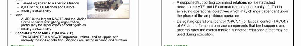
25 Executive Summary EX.1 INTRODUCTION This dual-service NTTP M and is a revision and update of the legacy publication, NWP /FMFM 1-8. It provides the detail required by ATF and LF commanders and their staffs to plan and conduct amphibious operations. This publication describes: 1. The organization of the ATF and LF units to conduct the ship-to-shore movement of any type or size LF 2. The command relationships within and between these forces 3. The planning process to develop the landing plan 4. The execution of surfaceborne and airborne ship-to-shore movement. NTTP M/ serves as a doctrinal guide for operational staffs, unit commanders, and school commands. This NTTP/MCWP expands on current joint doctrine and governs the manner in which the Navy and Marine Corps execute movement ashore now and will execute such operations in the near future. It is in line with, and supplements, current joint amphibious doctrine contained in JP 3-02, Joint Doctrine for Amphibious Operations, and other relevant publications and documents. EX.2 PUBLICATION ORGANIZATION This NTTP/MCWP is organized along the same lines as the legacy NWP/FMFM, but has eliminated or updated outdated TTP. While this publication provides guidance for Navy and Marine Corps planners in the movement of personnel, equipment, and supplies from ships to the shore in support of the LF CONOPS, it also provides its users with the current joint and service references that address various aspects of ship-to-shore movement in greater detail and specificity. Chapter 1 provides an overview of amphibious operations and the ship-to-shore movement concept. Chapter 2 discusses ATF and LF organization and command relationships. Chapter 3 discusses planning and operational organization to execute the plan, and Chapters 4 and 5 cover surfaceborne and airborne ship-to-shore movement, respectively. The NTTP/MCWP also contains several appendixes. Specific chapter and appendix overviews are provided in Figure EX-1. EX-1 MAY 2007
26 Chapter/ Appendix Chapter/ Appendix Title Brief Description of Chapter/Appendix Contents 1 Overview Provides tactical planners with a ready reference and overview of characteristics and types of amphibious operations, the ship-to-shore movement concept, and highlights the ships, craft, and organizations participating in ship-to-shore movement operations. Terminology used in this chapter and throughout the publication is that found in JP 3-02, not the terminology that will eventually be used in ESG/ESF operations. 2 Organization and Command Provides the Navy and Marine Corps organizational and command relationships for planning and executing ship-to-shore movement. 3 Planning Covers the planning process for ship-to-shore movement and the manner in which the AO and landing area are organized to facilitate amphibious operations. Discusses the planning sequence for ATF and LF commanders to land troops, equipment, and supplies at prescribed times and places, and the organization to support the LF CONOPS ashore. 4 Conducting Surfaceborne Ship-to-Shore Movement 5 Conducting Airborne Shipto-Shore Movement A B C Landing Craft and Amphibious Vehicle Formations and Control Signals Identification Flags, Insignia, Markers, Lights, and Signals Landing Craft and Amphibious Vehicle Control Procedures Discusses the doctrine, methodology, and C2 for LF debarkation and surfaceborne ship-to-shore movement. Also covers planning considerations that should be taken into account when preparing to conduct surfaceborne ship-to-shore movement operations. Discusses the doctrine, command relationships, delegation of authority, and the C2 organization for conducting LF debarkation and airborne ship-to-shore movement. Stresses importance of coordination with surfaceborne assault or action forces, explains the manner in which helicopters and rotary-wing aircraft may be employed, and the organizations that control vertical assault operations during ship-to-shore movement. This chapter contains a considerable amount of new terminology and procedures. Depicts various formations for landing craft and amphibious vehicles. Depicts hand and arm signals for controlling displacement landing craft and amphibious vehicles. Depicts and discusses flags, insignia, markers, and lights used in surfaceborne ship-to-shore movement to identify, control ships, landing craft, and waves assigned to a landing beach. Describes the grid reference system of landing craft and wave control. Highlights difficulties inherent and inherent inaccuracies of the system, and introduces some alternative craft control procedures. D Salvage Operations Discusses the assets and procedures to salvage landing craft during ship-to-shore operations. E F G H I J Responsibilities for Loading, Stowing, and Offloading Landing Force Equipment The Tactical-Logistical Group Landing Force Support Party The Helicopter Support Team Transformational Concepts, Equipment, and Capabilities Planning Diagrams and Tables Covers, in general terms, Navy and LF responsibilities for loading, stowing, and offloading LF equipment. Covers the organization and functions of the TACLOG group and its relationship with the Navy control organization. Describes the manner in which the TACLOG group assists Navy control officers aboard ship in the ship-to-shore movement of troops, equipment, and supplies. Describes the organization, functions, operational and command relationships, and the planning involved in establishing the LFSP as it executes initial CS and CSS for the LF during ship-to-shore movement. Provides indepth coverage of HST fundamentals, organization, and responsibilities, as well as the operational aspects of providing CSS to the helicopterborne unit. Provides a brief description and overview of some of the transformational concepts, equipment, and capabilities that will impact on future amphibious operations and movement ashore. Depicts various diagrams and tables originally contained in Chapter 3. Generally applicable to MEB- /MEFlevel operations, but moved to preserve them for possible future use. Figure EX-1. Publication Organization MAY 2007 EX-2
27 EX.3 TRAINING AID This section provides a training aid in the form of a PowerPoint presentation. The PowerPoint presentation provides an overview of this publication, including: 1. Summarization of the publication's organization by chapter and appendix 2. Methodology used in developing the publication. A copy of the presentation is provided in the remainder of this section. To view the PowerPoint presentation, click here. EX-3 MAY 2007

28 MAY 2007 EX-4
29 EX-5 MAY 2007

30 MAY 2007 EX-6

31 EX-7 MAY 2007

32 MAY 2007 EX-8

33 EX-9 MAY 2007

34 MAY 2007 EX-10
35 CHAPTER 1 Overview 1.1 PURPOSE This NTTP serves as a guide for Navy and Marine Corps commanders and staffs, unit commanders, and school commands. It discusses the doctrine, command relationships, and TTP in planning and executing ship-to-shore movement during amphibious operations. While MPF operations and MSC ships are often integral to amphibious operations and ship-to-shore movement, MPF and MSC operations are not discussed in detail in this publication. Detailed information on such operations is found in JP 3-02; NWP , MSC Support of Amphibious Operations; NTTP /MCWP 3-32, Maritime Prepositioning Force Operations; and NTRP , Naval Beach Group Support Element Operations. This publication describes: 1. The organization of ATF and the LF units to conduct the ship-to shore movement of any type or size LF 2. Command relationships within and between these forces 3. The planning process to develop the landing plan 4. The conduct of surfaceborne and airborne ship-to-shore movement. Chapter 1 provides tactical planners with a ready reference and an overview of the characteristics and types of amphibious operations, and the ship-to-shore movement concept. It also highlights the ships, craft, and organizations participating in ship-to-shore movement operations. However, because the command relationships, staff structure and composition, C2, and specific missions are still being developed, throughout this publication terminology specific to the ESF and ESG concepts is not used. Terminology and definitions associated with amphibious operations are found in JP 1-02, Department of Defense Dictionary of Military and Associated Terms; JP 3-02; and MCRP 5-12C, Marine Corps Supplement to the Department of Defense Dictionary of Military and Associated Terms. For purposes of this publication, the following definitions apply: 1. An ATF is a Navy task organization formed to conduct amphibious operations. 2. An LF is a Marine Corps or Army task organization formed to conduct amphibious operations. 3. An AF is an ATF and an LF together with other forces that are trained, organized, and equipped for amphibious operations. 1-1 MAY 2007
36 1.2 AMPHIBIOUS OPERATIONS BACKGROUND AND OVERVIEW An amphibious operation is a military operation launched from the sea by an AF embarked in ships or craft with the primary purpose of introducing an LF ashore to accomplish the assigned mission. Such operations include the following phases: planning, embarkation, rehearsal, movement, and assault. A brief discussion of the five phases is provided in sequence in this section and in Figure 1-1. However, depending on the nature of the operation, the location, readiness, and availability of naval and LF assets, and the amount of time available to organize, plan, and execute, the phases do not always occur in the aforementioned order. Generally, forward-deployed AFs use the sequence: embarkation, movement, planning, rehearsal, and assault. A more detailed description of each phase is contained in JP For detailed information on the embarkation phase, see JP , Joint Doctrine for Amphibious Embarkation; MCRP G, Unit Embarkation Handbook; and MCRP 4-11C, Combat Cargo Operations Handbook. Upon receipt of the order initiating the amphibious operation, naval and LF planning begins. This order may come in the form of a WARNORD, an alert order, a planning order, an OPORD, or from a combination of these orders. The order normally specifies the purpose of the mission, command relationships, and scope of the action to be taken. Additional information on the contents of the order initiating the amphibious operation and a detailed discussion of support relationships are contained in Chapter 2 of this publication and Chapter II of JP When an order is received directing a mission that requires ship-to-shore movement, planning begins with the LF CONOPS. This concept outlines the intentions of the LF commander regarding how operations ashore will be conducted. It includes the organization for the landing and the CONOPS ashore. The CONOPS ashore is the supported commander's tactical plan for the LF to accomplish the assigned mission. It determines which LF units are required at the various landing locations within the landing area. Further, the CONOPS ashore is used to guide the assignment of LF units to amphibious ships, landing craft, and aircraft for ship-to-shore movement. This concept is examined by appropriate commanders or their staff representatives for supportability and approved by the supporting commander prior to the commencement of detailed planning. Chapter 3 of this publication and Chapter IV of JP 3-02 contain detailed discussions of the amphibious planning process. With an approved CONOPS ashore, LF and naval requirements for mission accomplishment are consolidated and compared with the AF means and assets available. If necessary, additional assets are requested from appropriate higher authority. Should additional means and assets not be available, the CONOPS is adjusted accordingly, or another is developed. The landing plan is prepared after completing the final allocation of assets. This plan is composed of naval and LF documents which delineate the guidance and instructions to execute surfaceborne and airborne ship-to-shore movement. They are covered in detail in Chapter 3. When the landing plan is completed, embarkation planning begins. The assignment of personnel, equipment, and supplies to amphibious shipping and their sequence for embarkation constitute the loading plan. The loading plan is derived from and totally supports the landing plan. JP contains additional information on embarkation planning. MAY
37 Phase Planning Embarkation Rehearsal Movement Assault Description A continuous process from receipt of the order initiating the amphibious operation to terminate the operation. Results in: 1. LF concept of operations ashore 2. Landing plan 3. Loading plan 4. AF organization. Period during which the LF is embarked in shipping. For MEB- /MEF-sized operations, the LF may be organized into AEs and AFOEs. Normally conducted during the movement phase to test feasibility and adequacy of the landing plan, timing of detailed operations, combat readiness of participating forces, and test communications. Period when the AF departs embarkation/rehearsal area and proceeds to the AOA. May be organized into movement groups. Operations occurring during movement are: 1. Supporting operations 2. Advance force operations. Begins when enough of the AF is in position in the landing area to initiate the ship-to-shore movement and terminates with mission accomplishment. This phase includes: 1. Supporting arms 2. Ship-to-shore movement (Note 1) 3. Logistics/CSS (Note 1) 4. Patient movement. (Note 2) Notes: 1. These areas are discussed in detail in subsequent chapters and appendixes. 2. This area is discussed in NWP 4-02 and in greater detail in NTTP Figure 1-1. Planning, Embarkation, Rehearsal, Movement, and Action: Phases of an Amphibious Operation 1-3 MAY 2007
38 The AF transits from embarkation points to the AOA after the LF embarks. A rehearsal to test the landing plan is conducted during the movement phase, if feasible and time permits. During movement in support of MEB- / MEF-sized operations, the ATF may be organized into groups consisting of amphibious shipping with escorts for protection and combat logistics forces for sustainability. In such larger-scale operations, the LF is organized into echelons: the AE and the AFOE. Transport and movement groups, and the AE and the AFOE are discussed in Chapter 2. The AOA is a geographical area delineated in the order initiating the amphibious operation for C2. The objectives to be secured are contained within this order. The area must be of sufficient size to ensure accomplishment of the mission and must provide sufficient area for conducting necessary sea, air, and land operations. Supporting, preassault, and advance force operations may be conducted while the AE is en route. The action phase commences when sufficient AF assets are positioned in the landing area to permit the commencement of ship-to-shore movement. The landing area is the part of the objective area within which the LF comes ashore. It includes the beach, approaches to the beach, transport areas, FSAs, airspace occupied by close supporting aircraft, and the land included in the LF's advance inland to the initial objective(s) Characteristics of Amphibious Operations Amphibious operations encompass a wide variety of missions that support the commander's campaign or OPLAN. The essential characteristics inherent in amphibious operations are discussed in Paragraphs through Integration Between Navy and Landing Forces An amphibious operation requires close coordination among the naval forces, the LF, and other designated forces. Ordinarily joint or combined in nature, an amphibious operation is typified by integrating forces trained, organized, and equipped for disparate functions Rapid Buildup of Combat Power From the Sea to Shore An essential requirement in an amphibious assault is the uninterrupted projection of combat power ashore to support the CONOPS. Naval forces should also provide continuous support for forces ashore Task-Organized Forces AFs are task organized based on the mission, and are capable of carrying out multiple missions to support joint, allied, and coalition amphibious operations. The ATF's C2 capabilities and those of the embarked LF facilitate the accomplishment of multiple missions as well as joint and multinational force integration Unity of Effort and Operational Coherence The complexity of amphibious operations and the vulnerability of forces so engaged require exceptional unity of effort and operational coherence. This includes the full integration of organic assets as well as those of other joint or multinational forces. MAY
39 Readiness AFs are immediately available to respond to smaller-level contingencies. By maintaining proficiency and overall warfighting readiness, AFs can provide a wide range of services that support peacetime and combat operations Flexibility The flexibility inherent in AFs permits political leaders and commanders to shift focus, reconfigure, and realign forces to handle a variety of contingencies by providing a wide range of weapons systems, military options, and logistic or administrative capabilities. For MEB- /MEF-sized operations, AFs are viable in carrying out forcible entry and air interdiction operations. Smaller scale AFs are fully capable of conducting NEOs, disaster relief, shows of force, maritime interdiction, and HA. Additionally, they can exercise sea control and the C2 capabilities of these forces can provide an operating platform for a joint HQ element to support or complement diplomatic efforts Self-Sustainment AFs are capable of operating in forward areas without significant land-based supply infrastructure. UNREP and on-station replacement or rotation of personnel and ships allow such operations to continue indefinitely. To further enhance the sustainability of amphibious operations, forward logistics sites may be established Mobility AFs, through strategic and tactical mobility, have the ability to monitor a situation passively, remain on station for a sustained period, respond to a crisis rapidly, and deploy in combat. Their mobility enables these forces to respond from OTH. If diplomatic, political, or economic measures succeed, AFs can be quickly withdrawn without further action ashore. They can also respond to indications of impending crises by relocating rapidly, usually independent of fixed logistics. In combat, the ability to position these forces provides commanders with a tactical and operational advantage Types of Amphibious Operations Amphibious operations encompass assaults, withdrawals, demonstrations, raids, and other operations in a permissive, uncertain, or hostile environment. These operations are covered in greater detail in Chapter I of JP Amphibious Assault An amphibious assault involves establishing a force on a hostile or potentially hostile shore. Moreover, the organic capabilities of a MEB- or MEF-sized AF, including fire support, logistics, and mobility, can facilitate access to a crisis area by forcible entry. JP 3-02 and JP 3-18, Joint Doctrine for Forcible Entry Operations, provide additional large-scale amphibious assault information Amphibious Withdrawal An amphibious withdrawal is the extraction of forces by sea in naval ships or craft from a hostile or potentially hostile shore. 1-5 MAY 2007
40 Amphibious Demonstration An amphibious demonstration is conducted for the purpose of deceiving the enemy by a show of force with the expectation of deluding the enemy into an unfavorable COA Amphibious Raid An amphibious raid is a swift incursion into or temporary occupation of an objective followed by a planned withdrawal Other Amphibious Operations In addition to projecting power, other operations conducted by AFs include NEOs, HA, or civil support operations. 1.3 SHIP-TO-SHORE MOVEMENT CONCEPT Ship-to-shore movement is that portion of the assault phase of an amphibious operation that includes the deployment of the LF from amphibious shipping to designated landing areas. Its objective is to land troops, equipment, and supplies at prescribed times and places and in the organization for landing necessary to support the LF CONOPS ashore. Ship-to-shore movement is surfaceborne, airborne, or a combination of both. It may be initiated from OTH (beyond the opposing force's visual and ground-based radar range), nearshore, or a combination of both. It commences when the commander supporting LF operations orders execution by signaling, "Land the landing force!" This is usually the ATF commander. It concludes when all assault shipping is unloaded. Unloading operations take place in two periods. The initial period in combat or opposed conditions is generally tactical and provides for the rapid buildup of combat power ashore and quick response to LF tactical and logistical requirements. In unopposed or noncombat conditions, the initial unloading period is administrative. As the seabasing concept matures, additional LF functions will remain afloat. However, the general unloading period remains primarily logistical and emphasizes the rapid unloading of appropriately identified personnel and materiel remaining in the amphibious shipping to support LF operations ashore. 1.4 LANDING MEANS The ship-to-shore movement of troops, equipment, and supplies ultimately depends on the landing means available. These include amphibious ships, MSC ships, amphibious vehicles, landing craft, and vertical lift aircraft. The general characteristics of these are described in the following publications: 1. NWP , Characteristics and Capabilities of U.S. Navy Combatant Ships 2. NWP 11-2, Characteristics and Capabilities of U.S. Navy Auxiliaries and MSC Ships 3. NTRP NWP NTTP series applicable CTMs 6. NTRP series applicable CTPs. MAY
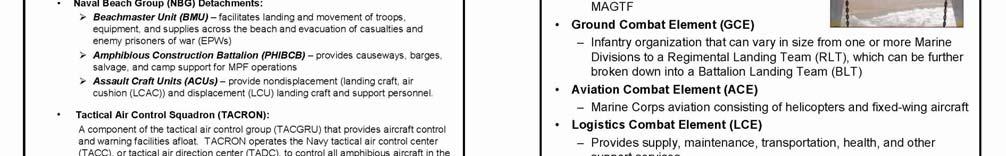
41 Figure 1-2 provides a comparison of amphibious ship troop, vertical lift aircraft, landing craft, and assault craft capabilities. Ship Class Troops Aircraft LCAC or LCU or EFV or AAV LHA 1,903 CH-46E, CH-53D/E, AH-1, UH-1, AV-8B, RH-53, SH-60, MV-22 (Note 1) LHD 2,104 CH-46E, CH-53D/E, AH-1, UH-1, AV-8B, RH-53, SH-60, MV-22 (Note 1) LPD (Note 3) CH-46E, CH-53D/E, AH-1, UH-1, AV-8B, SH-60 LPD CH-46E, CH-53D/E, AH-1, UH-1, SH-60, MV-22 (Note 1) 1 4 TBD 12 (Note 2) 3 2 TBD 12 (Note 2) 1 1 TBD TBD 14 LSD CH-46E, CH-53D/E, AH-1, UH-1, SH-60 4 (Note 4) 3 TBD 15 (Note 5) LSD CH-46E, CH-53D/E, AH-1, UH-1, SH TBD 15 (Note 5) Notes: 1. MV-22 is discussed in Section Tactical employment of AAVs is not normally conducted from an LHA or LHD. 3. Flag-configured LPD 4 carries approximately 60 fewer LF troops. 4. Five LCAC can be carried with vehicle ramp raised. 5. Administrative load. General Note: Tradeoffs in landing craft space available, but not at one-for-one ratio. Figure 1-2. Amphibious Ship Troop, Vertical Lift Aircraft, Landing Craft, and Assault Craft Capabilities Amphibious Ships Amphibious ships are specifically designed to embark, transport, land, and support the LF in assault and a variety of other amphibious operations. They are capable of being loaded and unloaded by naval personnel without external assistance. The following paragraphs describe amphibious ship classes LHA LHAs combine the operational capabilities of several types of amphibious ships in a single hull. This class has the primary mission of AMW. In addition to embarked commanders and their staffs, embarked units may include the following: 1-7 MAY 2007
42 1. GCEs 2. ACEs 3. AMCM detachments 4. Fleet support units, SEALs 5. TACRONs/TACGRUs 6. BMUs 7. PHIBCB 8. ACU detachments 9. FSTs/medical augmentation program personnel. Embarked units may also include LCEs, AAVs, vertical lift aircraft, LCUs and/or LCAC, and their assigned crews. The ship cannot embark all of these simultaneously; therefore, the number and type of units embarked generally depend on the nature of the mission and/or the composition of the AF. The LHA has vertical lift aircraft and V/STOL aircraft operating facilities greater than the LHD, a well deck capacity greater than LPD and the LSD, and a substantial vehicle and cargo capacity. The LHA can support embarked commanders and their staffs in any size AMW operation. It is an excellent joint C2 platform with facilities for a JCC, JIC, ATF TACC, SACC, TACLOG group, AATCC, HLSC, and central control of surfaceborne and airborne ship-to-shore movement. When augmented with an FST, an LHA can be designated to serve as a primary CRTS. A doctor and a dentist are assigned, and facilities include 4 medical and 2 dental ORs, 69 dedicated beds, and a frozen blood capability. The LHA has a secondary mission of power projection and a tertiary mission of sea control through the launch and recovery of the LF's ACE, and its aircraft to include the fixed-wing AV-8 Harrier V/STOL aircraft and a mix of the UH-1N, AH-1W, CH-46E, and the CH-53D/E rotary-wing aircraft. Additional detailed information on LHA class capabilities is contained in NWP , Characteristics and Capabilities of U.S. Navy Combatant Ships (U), and NTRP , LHA 1 Class Tactical Publication LHD The LHD's primary mission is AMW, and it is the Navy's largest amphibious ship. Similar to the LHA in design, mission, and capabilities, the LHD's significant improvements over the LHA include increased AV-8 support capabilities, a redesigned well deck that can accommodate three LCAC, expanded medical facilities, and upgraded C2 capabilities. However, the vehicle stowage capacity of the LHD is less than that of the LHA. When augmented with an FST, an LHD can be designated to serve as a primary CRTS. A doctor and a dentist are assigned to the LHD, and facilities include 6 medical ORs, 4 dental ORs, 41 ward and 23 intensive care beds, and a frozen blood capability. MAY
43 LHD class ships can support embarked commanders for any size strike force or AMW operations. The LHD can also support alternate force/sector commanders. NWP and NTTP , LHD 1 Class Tactical Publication, contain additional detailed information on LHD class capabilities LPD 4 Class LPD 4 Class ships transport troops and equipment for amphibious operations and land them in the assault area by means of helicopters in vertical assault or via landing craft or AAVs carried in the ship's well deck. The LPD is a variation of the LSD concept with increased troop and vehicle capacity, extensive ammunition and cargo stowage capabilities, and a smaller well deck. The LPD 4 Class can launch and recover Navy and Marine Corps helicopters, including the UH-1N, AH-1W, CH-46E, CH-53E, and AV-8 fixed-wing aircraft. Aircraft refueling and rearming can be conducted on the flight deck. All ships of the class, except LPD 4, have an expandable hangar and can provide service and maintenance to embarked helicopters. Limited interface testing has demonstrated that an unloaded deep skirt-configured LCAC can effectively enter and exit the LPD 4 Class well deck. However, increased craft height reduces the clearance between outboard cabin bulkheads and ship's catwalks, and between the bow thrusters and ship's overhead ducting that may result in craft or support ship damage. Until ongoing interface testing is completed, it is strongly recommended that LPD 4 Class ships not be used as operational platforms for deep skirt-configured LCAC. Should operational necessity require recovering deep skirt-configured LCAC, special attention should be given to the cautions and procedures contained in NAVSEA S9LCA-AA-SSM-010, Safe Engineering and Operations (SEAOPS) Manual for Landing Craft, Air Cushion (LCAC), Volume III, Appendix D. Flag-configured LPDs (LPD 7 through 13) provide C2 facilities for Navy and Marine Corps commanders and their staffs for AMW operations. These ships of this class can support a JCC, JIC, ATF TACC, and a SACC. Flag and nonflag-configured LPDs are equipped with TACLOG communication spaces for coordinating troop movement and logistics. The LPD 4 Class can function as a PCS for surfaceborne ship-to-shore movement. The LPD 4 Class has limited medical facilities, but can be designated as a secondary CRTS when augmented with medical and surgical personnel, and is equipped with the appropriate HSS capabilities. A doctor and a dentist are assigned, and facilities include 1 medical and dental OR, and a 6- or 12-bed ward. NWP and NTRP , LPD 4 Class Tactical Publication, contain additional information on the LPD 4 Class and its capabilities LPD 17 Class The LPD 17 Class ship's primary mission is AMW, and it is the Navy's newest amphibious ship. The capabilities of the LPD 17 Class include a state-of-the art C2 suite, substantially increased vehicle lift capacity, large flight deck, and advanced ship survivability features that enhance its ability to operate in the littoral environment. The LPD 17 Class provides AFs with enhanced operational flexibility. It can operate as part of an AF organized to accomplish a broad range of military objectives; or as an element of a "split AF" in which the LPD 17 is detached and operates independently to support low-risk amphibious operations. 1-9 MAY 2007
44 The well deck in the LPD 17 supports two LCAC or one LCU. Its aviation facilities are designed with two primary landing spots and a permanent hangar sized to provide organizational-level support for embarked aircraft. It can launch and recover Navy and Marine Corps aircraft, including the UH-1N, AH-1W, CH-46E, CH-53E, and the AV-8 fixed-wing aircraft. When the expanded spots configuration is certified, the flight deck will support simultaneous operation of four CH-46s; the flight deck will also support four MV-22 Osprey aircraft (two folded and two spread). As a secondary mission, the LPD 17 is equipped to function as a secondary CRTS when designated and augmented with medical and surgical personnel. A doctor and a dentist are embarked with a 24-bed ward and 1 OR. Additional information on LPD 17 Class capabilities is contained in NTRP , LPD 17 Class Tactical Publication LSD 41 Class The mission of the LSD 41 Class is to transport and launch AAVs and landing craft with its crews and embarked personnel in an amphibious operation. This ship class can embark up to four LCAC or three LCUs in the well deck. With its portable ramp removed, the ship can carry five LCAC. It is the primary support and operating platform for LCAC and may be used as the PCS or LCAC control ship. LSD 41 Class ships can also provide limited docking and repair services as a boat haven for small ships and craft. LSD 41 has two primary helicopter spots, and can handle Navy and Marine Corps helicopters currently in the inventory. The ship has no helicopter hangar. Aircraft fueling and rearming can be conducted on the flight deck. LSD 41 is not designed to embark commanders and its staffs, but is equipped with TACLOG communication spaces for coordinating troop movement and logistics. LSD 41 Class ships have a doctor and dentist assigned, but have limited medical facilities. These ships have two dental ORs and a medical OR. LSD 41 can be designated to serve as a secondary CRTS when augmented with medical and surgical personnel and equipped with the appropriate HSS capabilities. Additional information on LSD 41 Class capabilities is contained in NWP and NTRP , LSD 41 Class Tactical Publication LSD 49 Class The LSD 49 Class is designed to transport and land troops and their equipment by means of landing craft, AAVs, and helicopters. It may be used as the PCS or LCAC control ship. It differs from the LSD 41 Class in that it has significantly expanded cargo and ammunition stowage facilities. Its reduced well deck capacity precludes carrying more than two LCAC, and this class has two helicopter spots. Additional information on LSD 49 Class capabilities is contained in NWP and NTRP Casualty Receiving and Treatment Ship The ESG commander designates specific amphibious ships as primary CRTSs to provide Level II HSS to the LF during expeditionary operations. Large-deck amphibious ships (LHAs, LHDs) are normally assigned as primary MAY
45 CRTSs. FSTs are operationally assigned on TAD orders to large-deck amphibious assault ships to provide Level II surgical support to support an ESG with embarked MAGTF. The ESG commander may designate other amphibious assault ships as secondary CRTSs. At a minimum, a secondary CRTS should have the capability to receive and treat casualties, provided appropriate medical materiel and personnel are available to provide resuscitative care. Ships normally designated as secondary CRTSs include LPD and LSD class ships Military Sealift Command MSC is the sea transportation component for USTRANSCOM. MSC's mission is to provide ocean transportation of equipment, fuel, supplies, and ammunition to sustain U.S. forces worldwide during peacetime and in war for as long as operational requirements dictate. The command operates ships that provide combat logistics support to U.S. ships at sea; special mission support to U.S. government agencies; prepositioning of U.S. military supplies and equipment at sea; and ocean transportation of DOD cargo in peacetime and war Military Sealift Command Ships MSC owns or charters a number of ships that can support and have a significant impact on large-scale (MEB- /MEF-sized) amphibious operations. Assigned by MSC, they may be MSC nucleus fleet ships, contract-operated MSC ships, MSC-controlled time or voyage chartered commercial ships, or MSC-controlled ships allocated by the MARAD to MSC. The MSC force consists of four programs: APF, the NFAF, special mission ships, and sealift ships. MSC can also activate and employ another group of ships: the RRF. These ships provide the following capabilities: hospital support, troop transport, tankers, heavy lift, cargo (breakbulk, container, and RO- RO), special purpose (T-AVB), and T-ACS. Once activated, OPCON of MSC ships resides with a numbered fleet commander or CJTF. Additional information on MSC support for amphibious operations and ship-to-shore movement is contained in NWP Afloat Prepositioning Force MSC's APF is an essential element in the power projection triad: sea shield, sea strike, and seabasing. As a key element of seabasing, prepositioning ships make it possible to deploy on short notice the vital equipment, fuel, and supplies to initially support U.S. military forces whenever needed. The program includes long-term chartered commercial vessels, activated RRF ships, and U.S. government-owned ships. All are crewed by CIVMARs provided by companies under contract by MSC. Prepositioning ships are loaded with combat equipment for the Army, Air Force, Marine Corps, and Navy, as well as fuel for the DLA. APF ships are positioned in strategic areas around the world and are divided into three separate elements: the combat prepositioning force, the MPF, and the logistics prepositioning force Combat Prepositioning Force Combat prepositioning force ships provide quick-response delivery of Army equipment for ground forces from strategic locations. The majority of this force consists of LMSR vessels loaded with combat equipment. Other combat prepositioning force ships carry ammunition as well as sustaining and support cargo such as purification units, food, and initial CS equipment MAY 2007
46 Maritime Prepositioning Force MPS can offload instream with organic cargo-handling equipment and landing craft if port facilities are unavailable. In either situation, a permissive environment is required. The three MPSRONs, which may depart their normal AOs to support contingencies, are: 1. MPSRON ONE is responsible for TACON of MPS usually located in the Mediterranean and eastern Atlantic Ocean. 2. MPSRON TWO has TACON of MPS usually located in or near the island of Diego Garcia in the Indian Ocean. 3. MPSRON THREE has TACON of MPS usually located in the Western Pacific Ocean near the islands of Guam and Saipan. Detailed information on MPF operations and Navy cargo handling is found in NTRP and NTTP M/MCWP 3-32, Maritime Prepositioning Force Operations Logistics Prepositioning Force The logistics prepositioning force consists of ships that carry Air Force ammunition. Other ships in this element include MCDS vessels that carry ordnance for the Navy and have the capability to operate as shuttle replenishment ships for Navy strike groups. Ships in this force also carry DLA petroleum products for contingency use and include OPDS tankers. T-AVBs provide dedicated sealift for movement of an aviation IMA to support the rapid deployment of Marine fixed- and rotary-wing aircraft units. More specifically, in large-scale operations, the IMA supports the MAGTF's ACE, which includes a predesignated mix of aircraft. These maintenance facilities are packaged in mobile containers and include operational work centers and ready access supply stores. In situations where the IMA is moved ashore, the T-AVB can be used in a common-user sealift mode to provide a resupply capability in a conventional container or RO/RO configuration. The T-AVBs are assigned to MSC, but are maintained and operated under contract by MARAD in a ROS Naval Fleet Auxiliary Force NFAF ships are MSC-administered ships crewed by CIVMARs. NFAF ships and their basic functions are: 1. T-ATFs conduct towing and salvage operations. 2. T-AOEs conduct rapid replenishment of oil, ammunition, and dry and refrigerated stores. 3. T-AOs provide UNREP of fuel to Navy ships at sea and jet fuel for aircraft. 4. T-AFSs provide UNREP of all types of supplies, ranging from repair parts to fresh food and clothing. 5. T-AEs conduct ammunition transfer operations through a combination of at sea, alongside line transfers, and vertical lifts. MAY
47 6. T-AKEs are replacing the T-AO, T-AE, and T-AFS. 7. T-AH's primary mission is to provide rapid, and flexible and mobile acute medical care to Marine, Army, and Air Force units deployed ashore, and naval units afloat. The secondary mission is to provide disaster assistance or humanitarian relief operations. The second Geneva Convention contains specific provisions relating to the unique HSS mission of hospital ships under the laws of armed conflict. Because hospital ships may be employed in situations other than intensive combat, the type of practice within these specialties can change. Expeditionary HSS units, especially hospital ships and fleet hospitals/expeditionary medical facilities, may be increasingly employed in protracted operations that require extensive community hospital functions. The MTF CO/OIC should determine the extent of practice modification basing the decision on the facility's equipment, supplies, and personnel, and on the population receiving care. Details are provided in NTTP , Hospital Ships. There are 2 T-AHs, and each contains 12 ORs and a 1,000-bed hospital facility. Normally kept in ROS, when called into action, they can be ready to sail in 5 days with a crew of 70 CIVMARs and more than 1,200 military medical personnel Special Mission Ships MSC's special mission ships provide operating platforms and services for unique U.S. government and federal government missions. These ships include oceanographic and hydrographic survey ships, a cable-laying ship, missile range implementation ships for missile flight data collection and tracking, ocean underwater surveillance ships, and some chartered vessels for unique U.S. government operations, including deep water SAR missions and Navy submarine test support escort. Both CIVMARs and contractor-employed mariners operate special mission vessels. Embarked military personnel, civilian scientists, and related technicians conduct technical work, research, and communications. Recent additions to MSC's special missions program are the command ships, USS MOUNT WHITNEY (LCC 20) and USS CORONADO (AGF 3). Navigation, deck, engineering, laundry, and galley services are provided by MSC CIVMARs, while the remainder of the crew is military. A Navy captain commands these ships Sealift Program The mission of MSC's sealift program is to provide high-quality, efficient, and effective ocean transportation for the DOD and other U.S. government agencies. The program is divided into three project offices: tankers, dry cargo, and surge Tankers MSC works closely with the DFSC to transport petroleum products to DOD stowage and distribution facilities around the world, as well as to deliver fuel to MSC oilers and other Navy fleet oilers at sea Dry Cargo DOD's dry cargo is shipped via U.S.-flagged commercial ships. Cargo ships under charter to MSC carry approximately 20 percent of this cargo MAY 2007
48 Surge Surge sealift includes three key resources that are kept in ROS until needed for a crisis or contingency. Surge ships include FSSs, LMSRs, and RRF ships, which are described as follows: 1. FSS are government-owned USNS RO/RO ships assigned to MSC and operated under contract by merchant shipping companies. These are the fastest ships in the world (traveling at speeds of up to 30 knots). They are ideally suited to carry tanks, helicopters, and other military vehicles and supplies. The eight ships of this class (T-AKR) together can lift nearly the equivalent of a full Army mechanized division. These ships can be ready to sail in 96 hours. 2. MSC's LMSRs have 380,000 ft 2 of cargo space, can achieve speeds of up to 24 knots, and can be ready to sail in 96 hours. LMSRs are equipped with board ramps and cranes to assist in loading oversize cargo, including helicopters, M1A1 tanks, and armored personnel carriers. 3. The RRF is an element of the NDRF. This fleet of nearly 48 ships is maintained by MARAD in peacetime. When activated in wartime or in response to other contingencies such as humanitarian operations or military exercises, the RRF comes under the control of MSC. RRF ships are crewless, but are maintained in class with certificates as approved by the ABS and the USCG. They are normally kept in 4-, 5-, 10-, or 20-day ROS. RRF ships include RO/RO ships, heavy-lift ships, crane ships, breakbulk ships, tankers, and other ships not readily available in the U.S. commercial market Vertical Assault Aircraft Vertical assault aircraft employed in ship-to-shore movement are organic to the LF, and their employment is primarily determined by the MAGTF commander. They are used for troop and equipment transport, escort, and C2 during vertical assault ship-to-shore movement. LF vertical assault aircraft may be transported in and operated from amphibious ships, as discussed in Sections through Flight deck certification status for each ship class specifying aircraft types, restrictions on day or night operations, and support facilities available is contained in NAVAIR 00-80T-106, LHA/LHD NATOPS Manual; or APP 2(F)/MPP 2(F), Helicopter Operations From Ships Other Than Aircraft Carriers (HOSTAC). The types of aircraft employed by a MAGTF when embarked as the LF are described in Paragraphs through CH-53D Sea Stallion and CH-53E Super Sea Stallion Heavy lift helicopters are designed to transport personnel, supplies, and equipment in support of amphibious and shore operations. Additional information on CH-53D/E operations is contained in MCWP 3-2, Aviation Operations CH-46E Sea Knight The CH-46E is a medium lift assault helicopter primarily used to move troops, and medium cargo and equipment. Additional information on CH-46E operations is contained in MCWP MV-22 Osprey The Osprey is a medium lift assault aircraft primarily used for the transport of troops, equipment, and supplies to and from amphibious ships and land bases. The Osprey is a multi-engine, dual-piloted, self-deployable, VTOL MAY
49 tilt-rotor aircraft designed for assault support across the range of military operations. It is replacing the CH-46E and CH-53D medium lift helicopters AH-1W Super Cobra The AH-1W provides escort, fire support, and fire support coordination to the LF during amphibious assaults and subsequent operations ashore. Additional information is contained in MCWP UH-1N Iroquois (Huey) The UH-1N is a light lift C2 aircraft that can carry a maximum of seven troops. Additional information is contained in MCWP Tactical Advantages Tactical advantages for the helicopter include: 1. Ability to ascend and descend vertically into small unprepared areas for loading and unloading troops, equipment, and supplies 2. Delivering fresh troops in organized units to the objective 3. Increasing the LF's flexibility and mobility 4. Increasing the depth of the battlefield 5. Providing speed significantly greater than that of ground transportation in moving around the battlefield 6. Ability to provide rapid MEDEVAC or CASEVAC with minimum additional shock or trauma to injured personnel Tactical Disadvantages Tactical disadvantages in employing vertical lift aircraft in ship-to-shore movement include: 1. Ability of low visibility, high winds, icing, or other severe weather conditions to limit or eliminate aircraft operations 2. Intensive maintenance requirements 3. The requirement for precise C2 for deconfliction and coordination with other air operations and supporting arms Landing Craft Displacement and nondisplacement landing craft are used to land troops, equipment, and supplies. The capabilities and operating criteria of these landing craft are discussed in detail in NTRP ; NWP /MCRP A, Employment of Landing Craft Air Cushion (LCAC); MCRP 3-31B, Amphibious Ships 1-15 MAY 2007
50 and Landing Craft Data Book; LCAC SEAOPS; COMNAVSURFLANTINST/COMNAVSURFPACINST B, Joint Surf Manual; and COMNAVSURFLANTINST/COMNAVSURFPACINST , Wet Well Operations Manual. Brief descriptions of each craft are included below LCU The LCU is a highly versatile displacement craft designed to beach where hydrographic and weather conditions permit, unload/load, and retract while performing its mission to land heavy vehicles, equipment, personnel, and cargo in an amphibious operation. LCUs transport wheeled and tracked vehicles, general cargo, and personnel from ship to shore, shore to ship, shore to shore, and in resupply, backload or recovery operations. LCUs have also been adapted for other uses such as salvage operation and ferry boats for vehicles and passengers, including evacuees during NEOs. These craft are usually preloaded and lifted to the landing area in LHA, LHD, LSD or LPD well decks LCM 8 The LCM 8 is another displacement craft whose stated mission is to land personnel, supplies, and equipment on the beach in an amphibious assault or to operate in support of MPF operations. It is also used for lighter and utility work in harbors. However, because the craft is no longer routinely deployed in amphibious shipping, the LCM 8's primary mission is now supporting MPF operations, conducting ammunition transfers, and serving as a SAR platform Landing Craft Air Cushion The LCAC is a high-speed nondisplacement landing craft that complements the Marine Corps' rotary-wing aircraft (and ultimately the MV-22 tilt-rotor aircraft) in the conduct of ship-to-shore movement from OTH. The LCAC transports equipment, personnel, cargo, and weapons systems through the SZ and across the beach to landing points beyond the HWM and inland in a variety of environmental conditions. The combined effects of seas, ambient temperature, and craft load are considered in LCAC mission planning. Weather and environmental conditions can affect LCAC operations, but are of lesser concern than for other ship-to-shore delivery options. At OTH ranges of 12 to 100 nm, load and SWH permitting, LCAC offer a method to attain tactical surprise. In addition to supporting ship-to-shore movement during HA, IO, and support of military deception operations. These craft are preloaded and lifted to the landing area in LHA, LHD, LPD, or LSD well decks Amphibious Assault Vehicles AAVs, employed from well deck ships, are organic to the LF. They are described in Paragraphs through Amphibious Assault Vehicle Personnel Carrier The AAVP7A1 is an armored assault full-tracked landing vehicle. During ship-to-shore movement, this vehicle provides protected transport through rough water and the SZ to the beach for a crew of 3 and up to 21 combatloaded Marines. It can then carry troops to inland objectives after coming ashore. The AAVP7A1 provides a forcible entry amphibious capability that is unique to the Marine Corps. It can be fitted with an enhanced appliqué armor kit or sandwich-plated steel armor with a layer of Kevlar underneath to protect troops from high-caliber weapons fire. Its own firepower consists of a M2 50-caliber machinegun and a Mk 19 grenade launcher. The MAY
51 vehicle can move at speeds of up to 45 miles per hour on land and 8 knots at sea. The Marine Corps plans to replace the AAV with the EFV. The EFV is discussed in Appendix I Amphibious Assault Vehicle Command and Control The AAVC7A1 has the same basic characteristics as the AAVP7A1, but is designed to provide a mobile regimental or battalion tactical command post platform. The system consists of five radio operator stations, three staff stations, and two master stations. The command communication system contains equipment to provide external secure radio transmission between each AAVC7A1 vehicle and other vehicles and radios. It is armed with a 7.62-mm machinegun and can carry a crew of 3 with a commander and his staff of up to 10 personnel Amphibious Assault Vehicle Recovery The AAVR7A1 also has the same basic characteristics as the AAVP7A1. It is designed to recover similar or smaller sized vehicles, on land only, and carries basic maintenance equipment to provide field support maintenance to vehicles in the field. This equipment includes a generator, air compressor, welder, hydraulic crane, and a winch. It is armed with a M240G machinegun and can carry a crew of five Expeditionary Fighting Vehicle The EFV is the Marine Corps' replacement for the AAV7A1 and the AAV7C1. It is considered the keystone to the STOM and EMW concepts and will be the primary means of tactical mobility for the Marine rifle squad during the conduct of amphibious operations, including ship-to-shore movement, and subsequent ground combat operations ashore. The EFV is a self-deploying, high water speed, armored and fully tracked amphibious/infantry combat vehicle capable of transporting troops from OTH to inland objectives. While providing the speed and maneuvering capabilities to operate with the main battle tank (M1A1 Abrams) on land, the EFV can negotiate current obstacles to the LF (oceans, lakes, and rivers) as high speed avenues of approach and maneuver. It is operated by a crew of 3 and can carry up to 17 Marines with their combat equipment (assault load). There are two versions of the EFV: the EFV (P) and the EFV (C). They are organized into AA units that are organized and equipped to land the surface assault elements of the LF in a single lift from amphibious shipping to inland objectives. The specific tactics and operating doctrine for the EFV are still being developed. However, the current guiding publication is MCRP A, Tactics, Techniques, and Procedures for Expeditionary Fighting Vehicle Expeditionary Fighting Vehicle Personnel Variant The EFV (P)'s C4I system extends beyond the LOS to expand the battlespace of the MAGTF while minimizing vulnerability. With land mobility characteristics comparable to the M1A1, the EFV (P) can achieve speeds of up to 45 miles per hour and can cross the same obstacles and terrain features (i.e., trenches, hills, walls, and soft soils) as the tank. The EFV can achieve a high-water speed of 20 knots in a significant wave height (SWH) of 2 feet and can operate in a SWH of 3 feet. It can also traverse the SZ with 6- to 8-foot plunging surf MAY 2007
52 Expeditionary Fighting Vehicle Command and Control Variant The EFV (C) is designed and well suited for providing the EFV commander with a maneuver capability and the requisite information access to conduct close operations and maintain a high level of SA. It also provides the functional interface via systems applications to support the intelligence, maneuver, and firepower requirements of the commander and his staff, and provides secure voice and data capability between the crew and the embarked commander and staff. This vehicle provides a full range of C4I functionality required to operate as a regimental or battalion tactical echelon CP, and has workstation positions, communications systems, and MAGTF tactical C2 software systems applications for the commander and six staff stations Special Purpose Craft Special purpose craft are employed by LF RECON teams, SEALs, and troop units to conduct advance force operations, clandestine assault support, and raids. They are also used to carry boarding and inspection teams during MIO and VBSS operations. These small rubber or fiberglass boats are significantly impacted by surf conditions. Therefore, when opting to use these craft, operating areas are carefully selected and environmental conditions continuously monitored. Additional information on special purpose craft is found in NWP 3-05, Naval Special Warfare. The special purpose craft used in amphibious operations are described in Paragraphs through Combat Rubber Raiding Craft Capable of OTH operations, the CRRC is used for clandestine surface insertion and extraction of lightly armed SOF. Although primarily used by Marine Corps boat companies, CRRCs can be launched by various aircraft (airdrop (C-130 and C-141 and larger)/helo-cast), amphibious Mk V SOC, NSW RIBs, amphibious ship well decks, and from surface vessels with appropriate low davits. CRRCs may also be deck launched or recovered from surfaced SSNs or locked in and out from submerged DDS-equipped SSNs. The CRRC has a low visual electronic signature and can be cached by its crew once ashore. It is 15 feet, 5 inches long, weighs 265 pounds, and uses one 35 to 55-hp engine to attain speeds of up to 18+ knots depending on its load. Limited to operating in 8-foot combined seas, its nominal range is 36 nm, although its endurance is dependent on the size of the motor and amount of fuel carried. A small CRRC is also sometimes employed. The small CRRC is a 130-pound, motor-driven raft that can carry a maximum payload of 2,000 pounds. It can operate at 15 knots with four combat swimmers and equipment that weighs up to 1,000 pounds. Small CRRCs have not been modified to allow for submerged recovery Naval Special Warfare Rigid Inflatable Boat The primary mission of the NSW RIB is to provide a short-range, ship-to-shore insertion and extraction capability for SOF in a low to medium threat environment. Its secondary missions are to resupply SOF along coastal littorals, and conduct maritime surveillance and OTH operations. NSW RIB detachments can be configured for 6- month deployments and are fully compatible with Navy amphibious ships to include launch and recovery at sea. The detachment consists of two NSW RIBs, two trailers, two prime movers, two boat crews, and a DDP. The "A" model NSW RIB can be launched from ramps or amphibious ships. MAY
53 The NSW RIB is nearly 35 feet 11 inches long and weighs 14,000 pounds. Powered by a 470-hp diesel engine, it can achieve speeds of up to 47 knots with a 200-nm range. It carries a crew of three with up to eight passengers and is seaworthy up to sea state 3. The NSW inventory also includes 24- and 30-foot RIBs that are high-speed, high-buoyancy, extreme weather craft with the primary mission of tactical insertion and extraction of SEALs. During normal operations, these craft are limited to 10-foot combined seas and winds of 35 knots or less Mk V Special Operations Craft While not organic to the AF, the Mk V SOC can operate in support of amphibious operations, including ship-toshore movement. Its primary mission is medium-range SOF insertion and extraction in a low to medium threat environment. The craft's secondary mission is limited CPI. It is fully interoperable with PCs and NSW RIBs. Generally operated from an FOB ashore, a Mk V detachment is deployable by land, rail, two USAF C-5 aircraft, or a ship with appropriate flight deck and crane capabilities. A detachment consists of an MST and includes 10 crew and 8 MST personnel. It can be ready to deploy within 48 hours of notification and ready to commence day or night operations in support of amphibious operations within 24 hours of arrival at the FOB. The Mk V SOC is 82 feet long, weighs 57 tons, and powered by two 2285-hp waterjet engines. It has a maximum range of 600 nm and can achieve speeds in excess of 45 knots for 250 nm in seas state 2, 25 to 40 knots in sea state 3, and can survive through sea state Miscellaneous Vehicles and Support Components Miscellaneous craft, boats, and special purpose equipment and systems used to support ship-to-shore movement, establishing the logistics support operations, and the LF CONOPS are described in Paragraphs through Details are delineated in NTRP and NTTP M/MCWP Improved Navy Lighterage System INLSs are composed of 80-foot-long barge sections that lock together like building blocks to create a variety of floating structures. Powered barges will be equipped with 360 rotating water thrusters for propulsion and station keeping. These structures allow Navy ships to transport heavy equipment (such as tanks and trucks, and cargo) to include food, water, and equipment parts, between ships and from ship to shore when moorings have been damaged or are unavailable. The system assembles to form ferries, causeway piers, or ship ramps roll-off discharge platforms, providing the Navy and Marine Corps with a method of discharging cargo from strategic sealift ships and moving cargo to shore in case a port is denied, degraded, or unavailable, in environments greater than sea state 2. Fielding to MPSRONs will begin in fiscal year 2007 with full rate production modules (29 in total) slated for delivery to all three MPF squadrons through Lighter, Amphibious Resupply, Cargo-5 Ton LARC Vs are used by the BP for SZ salvage, recovery, dewatering, ship-to-shore movement, MEDEVAC/CASEVAC, C2 roles, ramp checks, and occasionally for transporting personnel and equipment MAY 2007
54 Causeway Section, Nonpowered Causeway sections are used to bridge the gap between LCUs and the beach, and facilitate the rapid ship-to-shore movement of wheeled and tracked vehicles and equipment. While CSNPs can be carried in LHA, LHD, LPD, and LSD well decks, they are almost exclusively carried to the AO by MPS ships, where they are assembled by the PHIBCBs into a causeway pier or CF Causeway Section, Powered CSPs are causeway sections configured with propulsion and steering equipment. When used in CF operations, a CSP section and CSNP sections are married together and can enter well decks or be loaded by crane while moored alongside to transfer cargo from ships in the transport areas to the beach. CSNPs can be carried in LHA, LHD, LPD, and LSD well decks, but are almost exclusively carried to the AO by MPF ships Causeway Ferry The CF's general mission is to provide a means for transferring equipment ashore when sufficient sections of causeway are unavailable to construct a shore-fast causeway pier. Additionally, the CF provides a method of transferring equipment and cargo from a cargo ship using ship cranes for offload Side-Loadable Warping Tug SLWTs are CSPs specially configured to maneuver, connect, beach, and retrieve other causeway sections; place and retrieve anchors; install offshore bulk fuel systems; act as pushers for causeway ferries; and be salvage craft. LHAs, LHDs, LPDs, or LSDs are capable of transporting SLWTs to the AO in their well decks; however, they are rarely delivered by anything other than MPF ships Amphibious Bulk Liquid Transfer System The ABLTS has replaced the AABFS and the AABWS. It is a buoyant system that prior to the availability of docking facilities provides the initial means whereby liquid products (fuel and water) are delivered to the LF ashore from MPF ships or amphibious ships. The ABLTS is assembled by the PHIBCBs Salvage Craft As mentioned in Section , LARC Vs may be used as a salvage craft and the PWC, or waverunner, is being tested as an alternative to the LARC V. If available, the LCM 8 may also be used as a salvage boat. Additional discussion of salvage operations is contained in Appendix D Free Boats Free boats are AAVs or landing craft that are available to carry commanders, C2 groups, or LF personnel ashore. The supported commander establishes free boat requirements. Requirements are weighed against the landing craft and AAV availability, as craft dedicated to this purpose are unavailable for troop lift, except on a second-trip basis. Operation of free boats in the vicinity of the LD and boat lanes prior to the landing of scheduled waves is coordinated with the PCO. MAY
55 CHAPTER 2 Organization and Command 2.1 PURPOSE This chapter provides the organizational and command relationships for planning and executing ship-to-shore movement. 2.2 ORGANIZATION The order initiating the amphibious operation specifies command relationships, available forces, and tasks. Flexibility is essential when developing the operational organization, and special emphasis is given to task grouping for economy of force, unity of command, and supported and supporting relationships between ATF and LF parallel chains of command Small-Scale Amphibious Operations A MEU-sized LF conducts small-scale amphibious operations. The LF is routinely embarked in forward-deployed amphibious shipping (an LHA/LHD, an LPD, and an LSD) referred to as an ESG or an ATF. The ESG has organic air, surface, and subsurface defense provided through the assigned surface combatant ships; expeditionary warfare provided by the amphibious ships and the MEU(SOC). ESGs provide JFCs and component commanders with credible, responsive, and flexible options to shape the battle, respond to crises, and protect U.S. and allied interests. The ESG includes the smallest MAGTF; nevertheless, it comprises a versatile, sea-based, operational force that can be tailored to a variety of missions in support of U.S. policy. These missions include quick-reaction crisis-response options in the maritime, littoral, and inland environs Medium- to Large-Scale Amphibious Operations A MEB- /MEF-sized LF conducts medium- to large-scale amphibious operations. Additional information is as follows: 1. Limited amphibious shipping dictates that the LF be organized into echelons. Only those AE LF units and equipment to execute the initial action are embarked in amphibious shipping. 2. To maintain LF integrity in the execution of the landing plan, a transport group may be formed for each landing area. This group can be subdivided into movement groups or units based on such factors as ports of embarkation, individual ship's speed, mutual protection en route to the AOA, and when they are required in the landing area. 2-1 MAY 2007
56 3. The interrelationship of ATF and LF tasks during planning and executing amphibious operations requires the establishment of parallel chains of command with corresponding ATF and LF commanders designated at various echelons for planning and C2. Such parallel chains of command also create special coordination requirements as supporting and supported relationships shift with the mission requirements of the amphibious operation. Therefore, except in emergencies, no significant decision contemplated by a commander in the chain of command that affects the plans, disposition, or intentions of a corresponding commander in another chain of command is made without consultation with the commander concerned. In emergency situations, the commander making an emergency decision will notify the affected commanders of action taken at the earliest practicable time. JP 3-02 and JP provide more information on echelons, and transport and movement groups Ship-to-Shore Movement Control The initial stage of a ship-to-shore movement is characterized by decentralized execution of the landing plan by subordinate commanders with the ATF and LF commanders maintaining centralized control through their respective control groups. The ATF commander controls the ship-to-shore movement and exercises control through the Navy control group for the surfaceborne assault and the TACGRU for the airborne assault. Each control group provides the positive control functions and coordination with supporting arms that are necessary to conduct their part of the ship-to-shore movement. A CCO and TACAIR officer plan and conduct the surfaceborne and airborne operations, respectively. The LF commander establishes two organizations, the TACLOG group and the LFSP, to facilitate and influence the ship-to-shore movement and to keep advised of the progress of the assault Navy Control Group The surfaceborne ship-to-shore movement of MEB- /MEF-sized LF may involve multiple landing beaches identified by colors. The organization of the Navy control group is based on the arrangement and number of those beaches. If several beaches are specified in the landing plan, the CCO designates a PCO at each landing beach for coordination and control of the surfaceborne operations. The airborne ship-to-shore movement from amphibious shipping into LZs is controlled by the TACGRU. The ATF commander controls air operations in the AOA through the TACC afloat. Air traffic control functions for the airborne ship-to-shore movement are delegated from the HCS of the TACC afloat to primary AATCCs, which are the air traffic control agencies for helicopter transport group and helicopter transport unit commanders. Chapter 4 provides a detailed discussion of the surfaceborne ship-to-shore movement and the Navy control group. Chapter 5 provides a detailed discussion of airborne ship-to-shore movement and the TACGRU Tactical Air Control Group The TACGRU, through the ATF TACC, is organized and equipped to control air operations in the AO. Control of aircraft movement from ships in sea echelon areas to LZs is exercised through the TACAIR officer in the ATF TACC. During airborne ship-to-shore movement, the ATF TACC coordinates aircraft movements with supporting arms and other air operations, and maintains a current status of vertical lift aircraft, fixed-wing aircraft, and landing platforms. MAY
57 The TACAIR officer is assisted by the HCSO when planning an air assault or other air operations. The HCSO is the OIC of the HCS of the ATF TACC. If several LZs are specified in the landing plan, the TACAIR officer designates a primary AATCC to provide air traffic control of the airborne operations into each HLZ. Chapter 5 provides a detailed discussion of the airborne ship-to-shore movement and the ATF TACC Landing Force Support Party The LFSP is the forward echelon of the LCE formed to facilitate ship-to-shore movement. It is a temporary task organization composed of ATF and LF elements established via a formal activation order from the LF commander to provide the LF with initial landing support and CSS during the ship-to-shore movement until relieved by the LCE. The LFSP's mission is to: 1. Facilitate the landing and movement of troops, equipment, and supplies across beaches and into LZs, ports, and airfields. 2. Assist in the evacuation of casualties and EPWs from beaches and LZs. 3. Assist in the beaching, retraction, and if necessary, the salvage of landing craft and amphibious vehicles. 4. Facilitate the establishment of the LCE, ACE, and NBG ashore. NTRP and Appendix G also discuss the organization and functions of the LFSP Tactical-Logistical Group The TACLOG is comprised of representatives designated by LF troop commanders to assist Navy control officers aboard control ships in the ship-to-shore movement of troops, equipment, and supplies IAW the landing plan. TACLOG detachments are collocated with the ATF and LF commanders, the TACAIR officer, CCO, PCOs, and helicopter transport group unit commander(s). The TACLOG is manned with personnel intimately involved in the development of the landing plan and capable of making rapid, sound decisions concerning ship-to-shore movement based on the LF commander's guidance and intent. Appendix F and JP , Joint Tactics, Techniques, and Procedures for Landing Force Operations, discuss the organization and functions of the TACLOG group. Figure 2-1 shows the control organization for conducting the ship-to-shore movement. 2.3 AMPHIBIOUS FORCE As defined in Paragraph 1.1, JP 3-02, and JP 1-02, an AF is an ATF and an LF together with the other forces that are trained, organized, and equipped for amphibious operations. 2-3 MAY 2007
58 ATF Commander LF Commander Tactical Air Control Group Navy Control Group Tactical Air Officer (Note) Central Control Officer (CCO) (Note) Tactical Logistics (TACLOG) Group ATF TACC Helicopter Coordination Section (HCS) Primary Control Officer (PCO) Red Beach Primary Control Officer (PCO) Blue Beach Primary AATCC Helicopter Logistics Support Center (HLSC) Legend Operational Control Coordination Liaison Tactical Control Note: ATF commander designates the tactical air officer or CCO as the singal point of contact to resolve issues and make decisions affecting the airborne or surfaceborne ship-to-shore movements. Issues involving air space management or safety of flight are always resolved by the tactical air officer. Figure 2-1. Control Organization During the Ship-to-Shore Movement Amphibious Task Force Depending on the size of the operation, the LF embarks in amphibious shipping or a combination of amphibious and MSC-chartered shipping for movement to the AOA. Chapter 1 provides the general characteristics of this shipping. The ATF commander is responsible for the task organization of the ships, preparation of the movement plan, selection of sea echelon areas in the vicinity of the landing area, logistics, and FP. The ATF commander is also responsible for LF debarkation until termination of the amphibious operation. The ATF staff ensures troops, equipment, and supplies are landed at the prescribed times, places, and in the formation required by the LF scheme of maneuver. Elements specific to this staff are described in the sections below. MAY
59 Naval Beach Group The NBG is a permanently organized Navy command within an AF comprised of a commander and staff, a BMU, a PHIBCB, and displacement/nondisplacement ACUs. Designed to provide an administrative group from which required naval tactical components may be made available to the ATF and LF commanders for any size amphibious operation, the NBG provides Navy elements in support of surfaceborne ship-to-shore movement and LFSP operations. During MPF operations, the NBG is task organized to form the NSE. The CNBG becomes the NSE commander and may also direct the NCHB elements, if assigned. The NBG and its support elements are discussed briefly in Paragraphs through , and covered in NTRP ; NTTP M/MCWP 3-32; and JP , Joint Logistics Over-the-Shore Beachmaster Unit The BMU is a commissioned naval unit of the NBG designed to provide the LFSP with a Navy component known as the BPT. The BMU facilitates the landing and movement of troops, equipment, and supplies across the beach and the evacuation of casualties and EPWs Amphibious Construction Battalion The PHIBCB is a permanently commissioned naval unit subordinate to the CNBG. The PHIBCBs provide an administrative unit from which personnel and equipment are formed into tactical elements and made available to appropriate commanders to operate pontoon causeways, transfer barges, warping tugs, assault bulk water and fuel systems, perform salvage tasks, and provide camp support and security. The PHIBCBs also have a limited construction capability for beach improvements and egress routes Assault Craft Units The ACUs are permanently commissioned naval organizations, subordinate to the CNBG, with the landing craft and crews necessary to provide lighterage for an amphibious operation. The ACUs provide displacement LCUs, LCMs, and nondisplacement LCAC in support of ship-to-shore operations, general offload, or MPF operations Tactical Air Control Squadron The TACRON is a component of the TACGRU that provides aircraft control and warning facilities afloat. The TACRON operates the ATF TACC, or TADC, to control aircraft in the AOA Landing Force An LF may be composed of Marine Corps and/or Army forces, other forces, and multinational forces. It is the highest troop echelon in the AF and, when Marines are embarked, encompasses the entire MAGTF Marine Air-Ground Task Force The MAGTF is the Marine Corps' principal organization for missions across the range of military operations. It is composed of forces task organized under a single commander and can respond rapidly to a contingency anywhere in the world. 2-5 MAY 2007
60 MAGTF forces are functionally grouped into four core elements: a CE, a GCE, an ACE, and an LCE. These elements are categories of forces, not formal commands. The basic structure of the MAGTF never varies, but the number, size, and type of Marine Corps units comprising each of the four elements are always mission dependent. MAGTFs are normally sized as a MEU/MEB/MEF, or in some cases, an SPMAGTF. MAGTF elements and organizations are discussed later in this chapter and in JP Figure 2-2 shows the MAGTF organization Command Element The CE is a permanent organization composed of the commander, executive and special staff sections, HQ section, and requisite communications support, intelligence, and RECON forces necessary to accomplish the MAGTF mission. The CE provides C2, intelligence, and other support essential for effective planning and execution of operations by the other MAGTF elements. The CE varies in size and composition, and conducts liaison with higher, adjacent, and supporting commands Ground Combat Element The GCE is task organized to conduct ground operations. It is usually constructed around an infantry organization, but can vary in size from a small ground unit of any type to one or more MARDIVs that can independently maneuver. The GCE also includes appropriate CS units. It is generally through the GCE that the MAGTF generates combat power through the use of firepower and mobility. Normally, there is only one GCE in a MAGTF Division The MARDIV is a balanced force of combat and CS units. It is a major administrative and tactical unit that is organized and equipped to conduct sustained combat operations with or without reinforcement Regimental Landing Team An RLT is a task organization for landing comprised of an infantry regiment reinforced by those CS organizations such as assault craft (AAV, EFV), LAVs, tanks, and combat engineers that are required for initiating its mission ashore. The RLT may be employed as an integral part of a division or as a semi-independent or independent maneuver unit. MAY
61 Figure 2-2. Marine Air-Ground Task Force Organization 2-7 MAY 2007
62 Battalion Landing Team A BLT is an infantry battalion normally reinforced by necessary combat and CS elements. It is the basic unit for planning an assault landing. The BLT may be employed as an integral part of the RLT or as a semi-independent or independent maneuver unit Aviation Combat Element The ACE is task organized to conduct aviation operations in direct support of the MAGTF. The ACE executes all or a portion of the six functions of Marine aviation necessary to accomplish the MAGTF's mission. These functions are AAW, OAS, assault support, EW, aerial RECON, and control of aircraft and missiles. The ACE is usually composed of an aviation unit HQ, and elements of MAGs, MACGs, and MWSGs. Depending on the MAGTF mission, the ACE may be reinforced with various other aviation units or their detachments. The ACE can vary in size from a small aviation detachment to a MAW. The ACE includes C2 agencies, combat, CS, and CSS units. Normally, there is only one ACE in a MAGTF. As the ship-to-shore movement progresses, the ACE commander phases the MACCS ashore Logistics Combat Element The LCE is task organized to provide the direct and general support necessary to accomplish the MAGTF mission. The LCE varies in size from a MLB associated with a MEU(SOC) to a CLR associated with a MEB, or a MLG associated with a MEF. It provides supply, maintenance, transportation, general engineering, health services, and a variety of other services to the MAGTF. Normally, there is only one LCE in a MAGTF. The development of combat logistics capability ashore to support the LF during the initial stage of an amphibious operation is accomplished by the LFSP Marine Expeditionary Force A MEF is the largest MAGTF and is the Marine Corps' principal warfighting organization. Normally commanded by a lieutenant general, it is task organized around a permanent CE and normally contains one or more MARDIVs, a MAW, and an MLG. Elements comprising the GCE, ACE, and LCE of MEBs and MEUs are drawn from MEF MSEs, and may be augmented by forces from other MEFs, MARFORES, other services, or coalition military forces. The size and composition of a deployed MEF can vary greatly depending on the requirements of the mission. A MEF is capable of missions across the full range of military operations, including amphibious assault and sustained operations ashore in any environment. It can operate from a sea base, land base, or both, and typically deploys with more than 45,000 personnel with up to 60 days of sustainment. The MEF is a tailorable and scalable force that can be equipped and task organized to conduct forcible entry operations, operate independently, serve as a JTF HQ, or operate as a JTF. When operating as part of a JTF, the MEF commander can operate as the JFLCC. The MEF is the only means for self-sustainable forcible entry into a region in which U.S. forces have been denied access. It can seize and hold airfields and ports to enable the introduction of follow-on MEF or joint forces. The MEF can then remain in theater to conduct the full range of military operations in support of the joint campaign. MAY
63 Ground Combat Element The MEF GCE is normally a MARDIV reinforced with appropriate CS units. The GCE may consist of multiple reinforced divisions under a single GCE commander. A MARDIV includes three infantry regiments, and artillery regiment, a tank battalion, AAV/EFV, LAV battalions, a RECON battalion, and a combat engineer battalion Aviation Combat Element The MEF ACE is a MAW task organized to perform all six functions of Marine aviation in direct support of the MAGTF commander. A single MAW, which may be augmented from other standing MAWs, MARFORES, other services, or coalition forces, forms the MEF ACE. The MAW is organized to form the ACE and can operate from ships, forward operating sites, permanent airfields, or expeditionary airfields. At the MAW level, when the MEF operates as part of a JTF, the ACE commander can operate as the JFACC Logistics Combat Element The MEF LCE is an MLG. It is structured to support a single-division GCE and a single-maw ACE. The MLG is a task-organized grouping of functional and cross-functional battalions that provide tactical-level ground logistics support to all elements of the MEF. The MLG may be tasked to provide operational-level logistics support in theater as a Marine logistics command. It provides a full range of supply, maintenance, transportation, general engineering, health services, and other services capabilities Marine Expeditionary Brigade A MEB is a mid-sized MAGTF that is smaller than a MEF, but larger than a MEU(SOC). It can deploy in amphibious shipping or be transported by strategic lift into an AO to link up with MPF assets. It is constructed around a reinforced infantry regiment, a composite MAG, and a CLR. Normally commanded by a BGEN or MGEN, and comprised of 8,000 to 18,000 Marines and Sailors, a MEB varies in size and composition and is task organized to meet the requirements of a specific situation. It typically deploys with up to 30 days of sustainment and can conduct combat operations of a limited scope. If the scope of operations expands beyond the capability of the MEB, additional forces can readily deploy to expand to a MEF. Capable of conducting forcible entry operations and other missions across the full range of military operations, a MEB can function as part of a JTF, as the JFEC, as the lead echelon of a MEF, or alone. A MEB may have other service or foreign military forces assigned or attached. It may be tasked with preparing for the subsequent arrival of the MEF, joint, or international forces, or the conduct of other specified tasks. Key MEB capabilities include: 1. Conduct amphibious operations as discussed in Paragraphs through Conduct sustained combat operations ashore as part of a larger force to achieve campaign or major operations objectives. 3. Conduct close and deep air support and aerial RECON operations. 4. Coordinate naval support of ground operations. 2-9 MAY 2007
64 Ground Combat Element The MEB GCE is tailored to accomplish a specific assigned mission. It is normally an infantry regiment reinforced with selected division units Aviation Combat Element The MEB ACE is a composite MAG that is task organized for the assigned mission and may consist of rotaryand fixed-wing aircraft, aviation C2 (including LAAD), and aviation ground support units. It is organized so the ACE commander's MACCS can be phased ashore early in amphibious operations. The MEB ACE is usually organized and equipped for early establishment in the objective area as forward operating sites are established or airfields in the objective area become available Logistics Combat Element The MEB LCE, or CLR, is task organized from the organic battalions of the MLG to provide CSS beyond the capability of the supported CE, GCE, and ACE. The CLR is organized to provide maintenance support, transportation support, general engineering support, supply support, disbursing services, legal services, health services, and postal services Marine Expeditionary Unit (Special Operations Capable) A MEU(SOC) is organized as a MAGTF consisting of a CE, a reinforced infantry battalion, a reinforced composite aviation squadron, a task-organized LCE, and an MSOC. The MEU(SOC) is typically associated with an ESG, consisting of approximately 2,200 Marines and Sailors, and is commanded by a COL. It normally fulfills the Marine Corps' forward, sea-based deployment requirements and deploys with up to 15 days of supplies. The forward-deployed MEU(SOC) is uniquely organized, trained, and equipped to provide the RCC or JFC with an expeditionary force. This force is inherently balanced, sustainable, flexible, responsive, expandable, and credible. The "special operations capable" designation means that the MEU(SOC) is embarked and deployed with an MSOC. The MSOC is normally under the OPCON of theater special operations command commander and under the TACON of the MEU commander. The MSOC is chartered to perform three core special operations missions (SR, DA, and limited FID). The MEU is chartered to perform the following missions: 1. Conduct amphibious raids. 2. Conduct amphibious assault. 3. Conduct security and stability operations. 4. Execute R2P2. 5. Conduct foreign military training. 6. Conduct HA/DR. 7. Conduct NEOs. MAY
65 8. Conduct TRAP. 9. Conduct limited expeditionary airfield operations. 10. Conduct airfield seizure operations. 11. Conduct joint/combined enabling operations. 12. Develop intelligence. Should the MSOC be tasked to disembark amphibious shipping for a separate mission, the MAGTF would be referred to as a MEU vice a MEU(SOC). A MEU(SOC) does not routinely conduct opposed amphibious assault operations and can only conduct amphibious operations of limited duration. Its special operations capability makes it well suited for crisis response, immediate reaction operations such as NEO, limited objective attacks, raids, and for acting as an advance force for a larger follow-on MAGTF. A MEU(SOC) can rapidly deploy and employ via amphibious shipping, by strategic airlift, through marshaling with MPF assets, or any combination thereof Ground Combat Element The MEU(SOC) GCE is normally a BLT, which is a reinforced rifle battalion of approximately 1,200 Marines. GCE attachments normally include artillery, engineers, LAR, antiarmor, AA, division RECON units, and a tank platoon Aviation Combat Element The MEU(SOC) ACE is normally a reinforced Marine medium helicopter squadron. It does not normally contain the aviation resources to conduct active AD of the landing area. The squadron is normally reinforced with a mix of transport helicopters, light attack helicopters, V/STOL attack aircraft, a detachment from the MACG that includes a LAAD section, and a detachment from the MWSG. A shore-based VMGR detachment is assigned to each MEU(SOC) ACE Logistics Combat Element The MEU(SOC) LCE, or MLB, is a task-organized component of the MLG. Relatively small, usually comprised of less than 300 Marines and Sailors, a CLB provides CSS such as supply support, maintenance support, transportation support, general engineering support, landing support, disbursing services, medical and dental services, legal services, and postal services Special Purpose Marine Air-Ground Task Force The SPMAGTF is a MAGTF organized, trained, and equipped with narrowly focused capabilities. It is designed to accomplish a wide variety of expeditionary operations, but its missions are usually limited in scope and duration. It is configured to accomplish specific mission(s) for which a MEF/MEB/MEU(SOC) would be inappropriate or too large. A SPMAGTF may be any size, but is usually a small force, MEU-sized, or smaller. SPMAGTFs are organized, trained, and equipped to conduct a wide variety of expeditionary operations MAY 2007
66 The SPMAGTF CE is structured for the conduct of operational functions and is tailored to the mission and task organization of the SPMAGTF Ground Combat Element The SPMAGTF GCE is normally at least a platoon-sized element Aviation Combat Element The SPMAGTF ACE is a task-organized Marine aviation detachment under an OIC. If required, the full range of Marine aviation capabilities can be included Logistics Combat Element The SPMAGTF LCE is typically a CSS detachment that is task organized to meet the specific service support requirements of the SPMAGTF. Depending on the mission of the SPMAGTF, the CSS detachment will be based on the unit upon which the operation is focused. For example, the CSS detachment can provide a landing support detachment if a port or airhead is used, or an engineer detachment if the mission entails construction or bulk fuel movement Marine Air-Ground Task Force Movement Amphibious assault shipping constraints and tactical considerations dictate that MEB- /MEF-sized MAGTFs be echeloned into the AO. For embarkation and movement, MEU(SOC)s are employed as single units. JP 3-02 describes echelons, organization for movement (transport and movement groups), sea routes, sea areas, and regulating points. 2.4 COMMAND RELATIONSHIPS The command relationships discussed in this section pertain to the planning and execution of ship-to-shore movement Amphibious Task Force and Landing Force Commander Command Relationships In the past, the terms "commander, amphibious task force" and "commander, landing force" have been used doctrinally to signify the two principal commanders assigned to plan, organize, and execute amphibious operations. These terms no longer connote command relationships. They are titles that refer to the senior ATF and LF commanders who are instrumental to the planning and execution of amphibious operations. The JFC, common superior commander, or establishing authority ensures unity of effort in achieving operational objectives by organizing the forces in a manner that best supports and accomplishes the overall mission. The most effective means are: 1. Establishing a support relationship between functional/service components 2. Delegating OPCON or TACON of AFs to functional/service components. MAY
67 Command relationship options are discussed in Chapter II of JP 3-02 and in JP 0-2, Unified Action Armed Forces (UNAAF). In amphibious operations, typically a support relationship is established between the ATF and LF commanders based on the complementary, rather than similar nature and capabilities of the maritime and ground forces. Other factors that impact on the type of command relationship chosen are the mission, nature and duration of the operation, force capabilities, C2 capabilities, assigned battlespace (threat), and recommendations from subordinate commanders. However, there is no intent to limit the common superior's authority to establish any appropriate command relationships Planning Relationships Regardless of the command relationships, when the order initiating planning for an amphibious operation is received, specified relationships are observed during the planning phase. The commanders designated in the order initiating the amphibious operation are coequal in planning matters and decisions. Planning for amphibious operations is discussed in detail in JP 3-02 and Chapter 3 of this publication Relationship Between the Ship's Commanding Officer and the Commanding Officer of Troops The CO of a ship transporting troops exercises command authority over persons embarked as prescribed by NAVREGS. While embarked, troop administration is a function of the COT, but is also subject to ship's regulations and SOP Relationship Between the Ship's Commanding Officer and Embarked Aircraft Units This relationship is discussed in Chapter Command of the Landing Force Support Party The LF commander commands the LFSP. The ATF commander directs NBG elements to form the BP and to report to the LF commander for planning. OPCON of the BPT may be passed to the LF commander at this time. Navy BPT commanders, as LFSP subordinates, retain command of Navy units ashore. The LFSP is discussed in detail in NTRP and Appendix G of this publication Relationship Between the Amphibious Task Force Surgeon and Landing Force Surgeon The ATF surgeon is the designated medical officer on the ATF staff and represents the commander in matters pertaining to the HSS for a projected amphibious operation. The LF surgeon is usually identified as the MEU or MEF surgeon, as is appropriate for the MAGTF level. In consultation with the LF surgeon, the ATF surgeon provides the OPLAN/OPORD medical section (Annex Q, Medical Services) to the ATF to ensure mutual support and fulfillment of supporting and supported commands' medical requirements to include patient movement MAY 2007
68 INTENTIONALLY BLANK MAY
69 CHAPTER 3 Planning 3.1 PURPOSE This chapter covers the planning process for ship-to-shore movement and the manner in which the AO and landing area are organized to facilitate amphibious operations. It discusses the planning sequence followed by ATF and LF commanders to land troops, equipment, and supplies at prescribed times and places, and the organization to support the LF CONOPS ashore. 3.2 BACKGROUND Detailed planning for ship-to-shore movement begins after the ATF and LF commanders approve the LF CONOPS ashore. The ship-to-shore movement plan is the compilation of detailed plans, tables, diagrams, and schedules prepared by the ATF and LF commanders. These documents are issued as an appendix to the amphibious operations annex of the OPORD; message OPORD supplements; or an APP 11, NATO Message Catalogue (NMC), formatted message (the OPTASK AMPHIB). The ship-to-shore movement plan is integrated with other elements of the OPORD and supporting plans (as applicable), and provides for the requisite CSS to the LF during the early stages of the operation. Altogether, the aforementioned documents comprise the landing plan. Many of these documents are designed for MEB- /MEF-sized operations; however, most can be modified for use in ESG/MEU(SOC)-sized missions. Those not included in this chapter are consolidated in Appendix J. 3.3 PLANNING PROCESS Developing a ship-to-shore movement plan demands a systematic approach to planning and adherence to doctrine. The six-step planning process highlighted in Paragraph is derived from, and essentially mirrors, the Marine Corps planning process delineated in MCWP 5-1, Marine Corps Planning Process. This planning process involves coordination among all levels of the established parallel chains of command supporting the ATF and LF commanders. Commanders' guidance, based on the LF CONOPS ashore, is provided to subordinate commanders, and the means to land the LF are tabulated and apportioned. Subordinate ATF and LF commanders prepare individual documents, such as those listed in Paragraph 3.2, for approval and consolidation with the naval and LF landing plans. JP 5-0, Doctrine for Planning Joint Operations; and MCDP 5, Planning, also provide detailed information on the planning process Tenets of the Marine Corps Planning Process The three tenets of the Marine Corps planning process, when adapted for amphibious operations, guide the ATF and LF commanders' use of their staffs and subordinates to execute assigned missions. These three tenets, topdown planning, the single-battle concept, and integrated planning, are discussed in Paragraphs through The overall process is explained in detail in JP 3-02 and MCWP MAY 2007
70 Top-Down Planning Because planning is a fundamental responsibility of command, commanders not only participate in the process, but they drive it. Two-way communication is the key to top-down planning, as commanders convey their intent and guidance to staff and component planners. They use planning as an avenue to gain knowledge and SA to support their decision making process. The commanders' guidance is translated into a CONOPS, and subordinate commanders use their guidance and CONOPS to accomplish assigned missions Single-Battle Concept Operations or events in one part of the battle or AO may have profound and often unintended effects on other areas and events. Therefore, commanders view the battlespace or AO as an indivisible entity. In amphibious operations, the single-battle concept allows commanders to effectively focus the efforts of AF elements on mission accomplishment. While the battlespace or AO may be conceptually divided into sectors such as deep, close, and rear to facilitate planning and decentralized execution, the commanders' intent ensures unity of effort by focusing on a single battle or mission Integrated Planning Integrated planning is a disciplined approach to planning that is systematic, coordinated, and thorough. It is based on the warfighting functions of C2, maneuver, fires, intelligence, logistics, and FP. Planners use these functions to integrate the planning effort and supervise execution of the plan. Planners use integrated planning to consider all relevant factors, reduce omissions, and share information across the functions. The key to integrated planning is the assignment of appropriate knowledgeable and experienced personnel to represent each functional area Planning Methods Two planning process methods may be applied to any amphibious operation: deliberate planning or rapid planning (also called CAP). While distinct in concept, in practice, deliberate and rapid planning can form a continuum and complement each other. If appropriate, deliberate planning is conducted early in the planning process. As the time for execution approaches, a transition can be made to rapid planning. Thus, deliberate planning may form the basis for later CAP, and rapid planning may be the revision of earlier deliberate plans Deliberate Planning Deliberate planning is the process generally used in MEB- /MEF-level operations for the deployment and employment of apportioned forces and resources. Deliberate planning occurs in response to a hypothetical situation or a situation that develops over an extended period of time. It is performed well in advance of expected execution, often during peacetime or before initiating a deliberate operation. Deliberate planners rely heavily on assumptions regarding the circumstances that will exist when the plan is executed Rapid Planning or Crisis Action Planning Rapid planning, or CAP, is the time-sensitive planning for the deployment, employment, and sustainment of assigned and allocated forces and resources that occurs in response to a situation that may result in actual military MAY
71 operations. Crisis action planners base their plan on the conditions and circumstances that exist at the time the planning occurs. CAP is usually less formal than deliberate planning and more responsive to changing events. In MEU(SOC) amphibious operations, CAP is also called R2P2. The R2P2 uses a compressed timeline that provides commanders and staffs with an accelerated planning mechanism that facilitates mission execution within 6 hours of WARNORD or alert order receipt. The goal of rapid planning is to expend less time on planning to provide the executing forces with the maximum time allowable to prepare for the mission. The key to successful rapid planning in amphibious operations is for ATF and LF commanders and their staffs to achieve a balance among sufficient time to develop a feasible COA, sufficient time to coordinate its essential details, and sufficient time to prepare for its execution. This balance cannot be achieved without proper mutual training and the conduct of exercises in preparation for real-world operations. Therefore, dedicated and well-coordinated training for MEU(SOC) and ATF staffs is always structured in detail and included from the very first days of predeployment workups. In rapid planning, commanders and their staffs shall be thoroughly familiar with potential contingencies or missions, and every individual involved with planning shall be thoroughly familiar with their role(s) in the planning process. A successful R2P2 process is predicated on each unit's early and timely retrieval or receipt of sufficient intelligence and related information; planning experience, foresight to make significant preparations in organizing, training, and equipping; information management; and highly refined, well-rehearsed SOPs. To best employ R2P2, commanders and their staffs develop capabilities in four areas: planning cells, planning and operations SOPs, intelligence, and information management Planning Cells To achieve the most effective and efficient rapid planning results, every effort should be made to standardize and maintain the composition and membership of the various planning cells. This is particularly true during the predeployment training program and deployment of the MEU(SOC), and its Navy counterpart, the PHIBRON. The planning cells usually employed by these two organizations include the CAT, or central planning cell; the battle staff, if employed; and the mission planning cells. These planning cells participate in frequent planning exercises that involve scenarios similar to those that might be encountered in real-world missions. These exercises serve to refine the LF and ATF staffs' ability to plan rapidly; allow planners to get to know the commanders and each other; and heighten SA regarding likely contingency missions and areas of operations. A comprehensive and challenging training program should result in planning cells understanding where they are to meet, what they will accomplish, and how much time they have to complete their planning efforts. Planning cells shall also be capable of conducting concurrent planning (simultaneous at different echelons of the same command) and parallel planning (between equivalent echelons of different) commands Planning and Operations Standard Operating Procedures SOPs are essential to rapid planning. ATF and LF planners should be familiar with their respective planning SOPs. Operations SOPs are equally important, because they allow planners to select proven and practiced tasks that provide viable solutions to tactical problems. SOPs also enable ATF and LF MSEs to carry out familiar tasks effectively and efficiently with minimal or no higher level guidance or communication. While it is impossible to develop SOPs for every conceivable mission, those that do exist should include a predesignated task organization; 3-3 MAY 2007
72 equipment and ordnance lists; elements of a landing plan; mission execution procedures; and an execution checklist with code words. SOPs should be studied, rehearsed, and executable with little advance notice Intelligence The LF and ATF commanders and their staffs shall be adept at anticipating possible contingencies based on continual analyses of classified and unclassified intelligence reports. Commanders should ensure their staffs, particularly the planners, are provided the latest intelligence, possible targets, area studies, and other information relevant to the assigned mission or potential missions Information Management The speed and volume of information flow in most operations, including ship-to-shore movement and related amphibious operations, can be voluminous and therefore overwhelming if not properly managed. Due to the time constraints inherent in R2P2, there is also less time for the commanders and their staffs to analyze information requirements. Therefore, it is critical that participants in the planning process be fully engaged in and realize the importance of their mission area, and that they share their knowledge and information in clear, concise, and simple presentations Six-Step Planning Process The cornerstone of amphibious operations execution is the six-step planning process. Its effectiveness and efficiency are enhanced if the methods and training discussed in Sections and are incorporated and implemented. Used in deliberate planning and CAP, and applicable to operations of any size or type, the six-step planning process provides logical procedures to follow from receipt of the order initiating an amphibious operation through the development of OPLANs, OPORDs, or OPTASKs. The process also provides ATF and LF commanders and their staffs with a means to organize planning activities, transmit plans to subordinate commands, and share a common understanding of the mission and the commanders' intent. Interactions among various planning steps allow a concurrent, coordinated effort that maintains flexibility, makes efficient use of time available, and facilitates continuous information sharing. It enhances the commanders' ability to make the primary decisions in most amphibious operations. Figure 3-1 provides a matrix of those decisions. The six steps of the process are: 1. Mission analysis 2. COA development 3. COA war game 4. COA comparison and decision MAY
73 Primary Decision May be Contained in the Order Initiating the Amphibious Operation Decision Decision Made Not Later Than Planning Step Determine AF Mission(s) X Mutual 1 Select AF Objectives X Mutual 1 Determine COAs for Development X Mutual 2 Select COA Mutual 4 Select Landing Areas Mutual 4 Select Landing Beaches Mutual 4 Determine Sea Echelon Plan ATF Commander 4 Select LF Objectives LF Commander 4 Select LZs and Drops Zones (DZs) Select Date and Hour of Landing 5. Orders development 6. Transition. LF Commander 4 X Mutual 4 Figure 3-1. Primary Decisions Responsibilities Matrix Chapter IV of JP 3-02, NTRP , MCWP 5-1, and MCDP 5 provide additional detailed information on the six steps of the amphibious planning process Naval Planning Naval planning for ship-to-shore movement focuses on developing the unloading, landing control, and patient movement plans/medreg. Unloading and landing control are discussed in detail later in this publication. MEDREG is covered in JP 3-02 and JP Landing Force Planning LF planning for ship-to-shore movement focuses on developing the sequence and organization for landing. The LF landing plan is the integration of naval and LF surfaceborne, and airborne ship-to-shore movement plans into a single coordinated plan that provides for the rapid projection of combat power or other LF assets ashore with the requisite CSS for sustained operations. To achieve this goal, the LF develops the sequence and organization for landing by: 1. Allocating or specifying landing means to subordinate commanders based on availability and IAW the LF CONOPS ashore 3-5 MAY 2007
74 2. Allocating blocks of serial numbers to subordinate commanders 3. Determining the LF's landing priorities 4. Tasking the GCE commander to prepare landing plans based on assigned tasks and priorities 5. Correlating and consolidating subordinate landing plans into the LF landing plan Landing Serials Discussion of the movement categories listed in Paragraph requires an understanding of landing serials and serial numbers Serials A serial is an element or group of elements (e.g., people, vehicles, equipment, supplies) within a series assigned a numerical or alphabetical designation to facilitate planning, scheduling, and control Serial Numbers A serial number is a reference number assigned to each serial to identify each element of the LF and those Navy elements to be landed prior to general unloading. Serial numbers are a means of identification, not a statement of priority, and are published in the SAT, which is included in the landing plan. The planned order for landing serials is published in the landing sequence table of the landing plan. Additional discussion of serial numbers and their allocation and assignment is contained in Paragraphs through Troop and Equipment Movement Categories LF troops and supplies are arranged in five movement categories for planning ship-to-shore movement: 1. Scheduled waves 2. On-call waves 3. Nonscheduled units 4. Prepositioned emergency supplies 5. Remaining LF supplies Scheduled Waves The ATF and LF commanders predetermine the time, place, and formation for landing scheduled waves. Scheduled waves consist of vertical lift aircraft, landing craft, or AAVs carrying serialized troops and their initial CSS ashore. MAY
75 After surfaceborne waves cross the LD or CDP, and vertical assault waves leave their DPs, the landing of scheduled waves normally proceeds without change to maintain the momentum of the operation and provide for the rapid projection of combat power or troops and equipment ashore. Surfaceborne waves land IAW the assault schedule. Airborne waves proceed IAW the HEALT. The assault schedule and the HEALT are discussed later in this chapter On-Call Waves On-call waves consist of elements the LF expects to need ashore early in the operation; however, their time and place of landing cannot be accurately predetermined. They are subject to immediate or emergency call and are positioned to be readily available after the specific hour on D-day at which landing troops land on the beach or LZ (H-hour). On-call waves consist of serialized combat units, CS units, and CSS, and are requested by tactical commanders ashore through the TACLOG group. Airborne on-call waves are positioned aboard ship, while surfaceborne on-call waves remain aboard ship or are positioned at the LD for displacement landing craft or at the CLA for LCAC. Because the units in on-call waves have a high priority for landing, their number should be kept to a minimum consistent with transportation asset availability and expected requirements ashore. The landing of any other elements may be pre-empted to permit the landing of on-call waves. If adequate numbers of landing craft are unavailable, on-call serials may wait aboard ship pending landing craft availability. Surfaceborne on-call waves are listed in the assault schedule, and vertical lift on-call waves are listed in the HEALT Nonscheduled Units Nonscheduled units are the remaining serialized units, with their CSS, whose landing is expected before the commencement of general unloading. The need for nonscheduled units ashore is usually not an immediate or emergency requirement. They are requested by tactical commanders through the TACLOG group via the supported unit TACNET or LFSP Control or Command Net, but are not normally landed or boated until requested. When the request is received by the PCO, the Bravo Net is used to direct the ship carrying the serial to prepare it for offload, and the PCO provides appropriate landing craft for moving the serial to the beach. When the serial is boated, displacement landing craft are dispatched to the PCS. LCAC are dispatched to the PCS or LCAC control ship. When the PCO has verified the LFSP is prepared to receive the serial, landing craft are dispatched to the beach. Once started, landing of nonscheduled units may be interrupted to permit landing of oncall waves, pre-positioned emergency supplies, or other selected supplies or equipment for which there is a greater requirement ashore. Nonscheduled units are generally moved ashore after completing scheduled landings by surface means, not via vertical lift aircraft. Each supporting LF commander prepares a landing sequence table that prioritizes the landing order for nonscheduled units. If the landing plan calls for landing CSS, Navy, or aviation elements across a beach before the nonscheduled units have finished landing, the LF commander informs the GCE commander of these units and their priority so they can be listed in the GCE commander's landing sequence table and forwarded to the LF commander for consolidation. The LF commander's staff then prepares an LF sequence table that consolidates all nonscheduled units. 3-7 MAY 2007
76 Prepositioned Emergency Supplies Prepositioned emergency supplies are designated by the LF commander to meet expected critical needs for CSS replenishment early in the ship-to-shore movement. These serialized supplies, available for immediate delivery ashore, are organized into floating dumps and prestaged airlifted supplies Floating Dumps Floating dumps are emergency supplies such as ammunition, water, lubricants, etc., preloaded in landing craft or AAVs. Floating dumps minimize the time that critically needed supplies can be transported to the beach. They are located in the vicinity of the appropriate control officer and are landed when requested by a tactical commander through the TACLOG group. The number and types of landing craft or AAVs used as floating dumps are specified in the landing craft employment plan, and landing craft and amphibious vehicle assignment table. Floating dumps report to PCS and are positioned per the assault wave diagram. Due to the limited numbers of landing craft or AAVs, floating dumps are not typically required or available in MEU(SOC)-sized operations Prestaged Airlifted Supplies Similar in purpose to floating dumps, prestaged airlifted supplies are positioned aboard air-capable ships. These serialized supplies can be delivered to either airborne or surfaceborne units. They are requested by a tactical commander ashore through the TACLOG group, and are listed in the HWSAT. A heliteam is analogous to a boat team Remaining Landing Force Supplies Remaining LF supplies are serialized, and consist of replenishment supplies and equipment not included in a unit commander's basic loads, floating dumps, or prestaged airlifted supplies. In MEB- /MEF-sized operations, these supplies are listed in embarkation documents and constitute the major portion of CSS transported into the landing area with the AE or AFOE. Certain supplies are selectively offloaded to maintain adequate replenishment levels ashore; however, the bulk of the remaining LF supplies are landed during general unloading. These supplies are generally moved ashore via surface means, not via air General Unloading The general unloading period is that part of the ship-to-shore movement in which unloading is primarily logistic in character, and emphasizes speed and volume of unloading operations. It encompasses the debarkation of LF units, supplies, and equipment from ships as rapidly as facilities on the beach permit. It is usually initiated on the recommendation of the LF commander and proceeds without regard to class, type, or priority of cargo, as permitted by the cargo-handling facilities ashore. General unloading begins when: 1. The progress with the CONOPS ashore is favorable, and permits discontinuing the structurally controlled movement of units and supplies ashore. 2. Sufficient quantities of all classes of supplies are already ashore. 3. BSAs are established. 4. Adequate security exists for supply installations ashore. MAY
77 Landing Craft Employment for General Unloading When general unloading commences, all available landing craft are employed. Landing craft previously ordered to load nonscheduled units complete those assignments, and if so designated, floating dumps are directed to the beach to offload Control Control during general unloading is delegated to each ship with DIRLAUTH with the PCO for the most efficient use of landing craft. Each ship advises the PCO hourly on offload progress by reporting the percent of PCVT operations (PCVT report) Offloading the Assault Follow-On Echelon The Navy control group organizes and conducts the offload of AFOE shipping. NTRP ; NWP ; and NTTP , Maritime Prepositioning Ship Operations, contain additional information on AFOE offloading and operations. 3.4 PREPARATION AND PROMULGATION OF KEY DOCUMENTS In ship-to-shore movement, the landing plan is composed of certain specific documents that present, in detail, the numbers of landing craft, aircraft, and other surface craft available for use and the exact personnel and equipment that will be loaded on each, along with embarkation and landing times. Some of these documents are applicable to amphibious operations of any size. Figure 3-2 lists landing plan documents. Figure 3-3 illustrates the preparation sequence and relationship between each document prepared by the ATF. While several of the documents listed in Figure 3-2 are more applicable to MEB- /MEF-sized amphibious operations, all are valuable tools for any size mission. The creation of and details in these documents are dependent on the landing plans, CONOPS ashore, and the guidance provided by the ATF and LF commanders Documents Prepared by the Navy Some or all of these documents may be included in the OPORD or OPTASK AMPHIB. 3-9 MAY 2007
78 ATF Commander's Responsibility Naval Landing Plan Landing Craft Availability Plan Landing Craft Employment Plan Debarkation Schedule Ship's Diagram Pontoon Causeway Plan Unloaded Plan Approach Schedule Assault Wave Diagram Landing Area Diagram Transport Area Diagram Beach Approach Diagram Sea Echelon Area Landing Control Plan Medical Regulating Plan Amphibious Assault Bulk Fuel System and Offshore Petroleum Discharge System Plan LF Commander's Responsibility Landing Force Landing Plan Amphibious Vehicle Availability Table Landing Craft and Amphibious Vehicle Assignment Table Landing Diagram Landing Force Serial Assignment Table Landing Priority Table Landing Force Sequence Table Assault Schedule Amphibious Vehicle Employment Plan Helicopter Availability Table Heliteam Wave and Serial Assignment Table Helicopter Enplaning Schedule Helicopter Landing Diagram Helicopter Employment and Assault Landing Table Ground Combat Element Landing Plan Consolidated Landing and Approach Plan Aviation Combat Element and Landing Force Aviation Landing Plan Figure 3-2. Landing Plan Documents MAY
79 Concept of Operations Medical Regulating Plan Landing Craft Availability Table Approach Schedule Landing Area Diagram Sea Echelon Plan Landing Craft Employment Plan Assault Wave Diagram Transport Area Diagram Debarkation Schedule Beach Approach Diagram Unloading Plan Landing Control Plan LF Commander Ship-to-Shore Movement Plan Legend Direction of Flow Coordination Note: Landing plan documents published in the OPORD are underlined. Figure 3-3. Navy Planning Responsibilities and Sequence Naval Landing Plan The naval landing plan organizes the landing area to facilitate the conduct and control of ship-to-shore movement, offload the LF, and provide for MEDREG. It incorporates the unloading, landing control, MEDREG plans, and other naval documents prepared to support LF planning. Figure 3-4 contains the format for the naval landing plan MAY 2007
80 CLASSIFICATION Copy of copies Commander ESG TWO CTF XX OPORD 1 { } FPO March 20 Appendix 3 (Ship-to-Shore Movement) to Annex R (Amphibious Operations) to CTF XX OPORD 1 { } Ref: (a) INITIATING DIRECTIVE DTG (b) CTF XX OPORD 1 { } NTTP M/MCWP Time Zone: H 1. Amphibious operations will be conducted as directed by Ref (a). D-day is 04 June 20XX. H- and L- hours are H June 20XX. The LF landing plan is in Ref (b). 2. Advance force operations will be conducted per Appendix 1. The AF will enter the AOA at H and proceed to the designated transport area. 3. Surfaceborne and airborne assaults will be conducted at Red and Green beaches and LZs Hawk and Falcon. AF movement to the transport area and the conduct of amphibious operations to achieve AF objectives will be per this appendix and Ref (b). Tab A provides detailed instructions for the Navy control and offload plans. Ref (b) is the LF's landing plan, and when combined with these instructions, constitutes the AF landing plan. 4. Force protection measures in the AOA will be established per Appendix Re-embarkation plan is in Appendix Supporting arms will be conducted per Appendix Medical regulating planning will be carried out per JP 3-02 and JP David Jones Captain, USN Chief of Staff Tabs: A. Surfaceborne ship-to-shore movement B. Airborne ship-to-shore movement Distribution: Per Annex Z Page Number CLASSIFICATION Figure 3-4. Example of a Naval Landing Plan Format (Sheet 1 of 2) MAY
81 Tab A Enclosure (1) Unloading Plan (2) Approach Schedule (3) Assault Wave Diagram (4) Assault Area Diagram (5) Transport Area Diagram (6) Beach Approach Diagram (7) Sea Echelon Plan (8) Landing Control Plan (9) Alternate Landing Plan Tab B Enclosure (1) Helicopter Landing Diagram (2) HEALT Representative Enclosures to Tabs A and B Figure 3-4. Example of a Naval Landing Plan Format (Sheet 2 of 2) Landing Craft Availability Table This table lists the type and number of landing craft available from each amphibious ship, and is categorized by total landing craft for naval and LF use. The landing craft availability table is the basis for landing craft assignment for ship-to-shore movement. It is prepared by the CCO. An example of the landing craft availability table is depicted in Appendix J, Figure J Landing Craft Employment Plan The landing craft employment plan is prepared by the CCO in conjunction with the NBG support element OIC. It specifies the number and type of landing craft, parent ship, ship to which craft will report, time to report to that ship, and the time period the craft will be attached. It allocates landing craft for pre-h-hour transfers as well as scheduled and on-call waves. Figure J-2 depicts an example of this document Debarkation Schedule The debarkation schedule provides for the timely and orderly debarkation of troops and equipment, and emergency supplies for surfaceborne ship-to-shore movement. It is dependent on the designated H-hour, and is approved jointly by the CO of each ship and the senior operational troop commander or COT. It lists the type of landing craft assigned, and the order of troop and equipment debarkation from the ship's well deck. It is supplemented by a ship's diagram. Figure J-3 provides a debarkation schedule example Unloading Plan The unloading plan establishes the sequence and designates the means for offloading the LF. It consists of the landing craft availability table and landing craft employment plan. The unloading plan must be closely coordinated with the amphibious vehicle availability table (Paragraph ), the amphibious vehicle 3-13 MAY 2007
82 employment plan (Paragraph ), the debarkation schedule, and the HWSAT (Paragraph ) prepared by the LF Approach Schedule The approach schedule indicates, for each scheduled wave, the times of arrival/departure from various points, including parent ship, rendezvous area, LD, CHA, CPs, and the landing beach. It provides wave numbers, courses and speeds to be followed by landing craft, and control ships' hull numbers. This schedule is prepared by the PCO, and submitted via the CCO to the ATF and LF commanders for consolidation and coordination with the overall ship-to-shore movement. An example of an approach schedule is depicted in Figure J Assault Wave Diagram The assault wave diagram displays scheduled waves, landing craft, control ships (if assigned), on-call waves, and floating dumps as they appear at H-hour. This diagram is prepared by the PCO based on wave compositions in the landing diagram (Paragraph ). The assault wave diagram presents a picture of the boat and LCAC groups, control ships' positions for each landing beach, and CLZs. An example of an assault wave diagram is depicted in Figure J Landing Area Diagram The landing area diagram provides the overall picture of the seaward approaches in the landing area and overlays an appropriate scale chart. It graphically depicts the landing area's most important details, such as beach designations, boat lanes, the LD, amphibious vehicle and CLAs, transport areas, and FSAs in the immediate vicinity of the boat and LCAC transit lanes. This diagram is prepared by the CCO. Figure J-6 provides an example of a landing area diagram Transport Area Diagram The transport area diagram overlays an appropriate scale chart that shows the area from the beach to 1,000 yards seaward of the outermost transport area anchorage or underway sector. The diagram is prepared by the CCO and provides a detailed picture of the transport area. An example of this diagram is depicted in Figure J-7. It includes the following: 1. Transport area(s) and assignment of ships to anchorage or underway sectors 2. HTAs 3. Control ships' positions (if assigned) 4. Boat and approach lanes 5. CLA, CDP, transit lanes, CPs, and CPPs 6. LDs 7. Amphibious vehicle launching area/aav underway launch track MAY
83 8. Causeway operating areas (MPF operations) 9. Designation of landing beaches 10. The following distances: a. From beach to center of transport area b. From beach to LD c. From approach lane marker ships to LD d. Width of beaches 11. The following courses (true and magnetic): a. From LD to beaches b. From approach lane marker ships to LD (if/as available or required) Beach Approach Diagram The beach approach diagram is typically used during MEB- /MEF-sized operations. The beach approach diagram is an overlay for a large-scale chart extending from each colored beach seaward to 500 yards beyond the LD. It can be modified for use in smaller scale operations. This diagram shows the position of control ships and landing craft in the vicinity of the LD after the last scheduled wave has landed, and identifies boat lanes for on-call waves and subsequent serials. An example of a beach approach diagram is shown in Figure J-8. It is prepared by the PCO and includes the following: 1. Designation (color and number) and dimensions of the colored beach 2. LD 3. Distance from beach to LD 4. Position of: a. PCS and SCSs b. Control boats (if/as available or required) c. Medical boats d. Salvage boats e. Traffic control boats (as available or required) 5. Return boat lanes MAY 2007
84 Sea Echelon Plan A sea echelon is a portion of the amphibious shipping that withdraws from, or remains out of, the transport area during a landing or an operation. It operates in designated areas to seaward in an on-call or unscheduled status. The sea echelon plan provides for the dispersion of amphibious shipping and establishes the sea echelon area. It also organizes the landing area to reduce the minehunting and minesweeping effort, and promulgates the priority sequence table (Paragraph ). The sea echelon plan is the responsibility of the ATF commander; however, because of its influence on embarkation and the landing plan, the decision to employ a sea echelon is reached jointly by the ATF and LF commander early in the operation's planning phase. An example of a sea echelon area is depicted in Figure J Considerations for Using a Sea Echelon In arriving at a decision regarding the use of a sea echelon, the commanders balance the desirable aspects of dispersion and mobility against the limitations they may impose on the landing plan. Factors that might drive amphibious ships further offshore and into a more widely dispersed formation include: 1. Range of shore-based weapons or missiles 2. Potential for CBR weapons attack 3. Littoral mining threat 4. Likelihood of attack by swimmers, small boats, or light aircraft 5. Increase in the element of surprise by remaining beyond the adversary's electronic sensor range. The following factors are balanced against others that dictate moving amphibious ships closer to the beach: 1. Achieving air supremacy, and surface and undersea superiority in the AOA 2. The delay associated with longer transit distances to the beach, thereby, slowing the rapid buildup of combat power, equipment, and supplies ashore 3. The possibility of an insufficient number of naval defensive forces that might dictate concentrating the ships to reduce screen requirements Navy Sea Echelon Responsibilities Employing a sea echelon does not alter the ATF commander's doctrinal or tactical responsibility to land and support the LF. The sea echelon plan should not be so restrictive that it reduces the LF's tactical effectiveness or jeopardizes mission accomplishment. Plan development includes: 1. Selecting the sea echelon area 2. Organizing the sea echelon area into operating areas MAY
85 3. Phasing amphibious shipping into the transport area 4. Providing C4I for ship-to-shore movement 5. Incorporating FP measures 6. Providing an alternate plan to land and reinforce the LF. A sea echelon plan is developed to regulate and efficiently control the movement of amphibious shipping and minimize connectivity requirements. This plan includes: 1. The composition of the sea echelon 2. A sea echelon overlay 3. A priority sequence table that delineates the order that ships from the sea echelon will enter the transport area to land scheduled waves, and conduct the initial and general unloading phases 4. The procedure for requesting ships out of priority sequence 5. General instructions, such as defining traffic patterns for entering and departing the transport area, unloading instructions, regulating points, etc Landing Force Sea Echelon Responsibilities The LF commander develops a CONOPS ashore that is compatible with the employment of amphibious ships in the sea echelon. During ship-to-shore movement, the ATF and LF commanders work together; however, the LF commander keeps commanders advised regarding logistic problems associated with the time delay inherent in the sea echelon concept. The time delay is the time involved from the moment a request for a ship out of sequence is received until that ship arrives in the transport area The Sea Echelon Commander The ATF commander usually delegates control of the sea echelon to a subordinate commander. The sea echelon commander exercises movement control over shipping in the sea echelon area, but coordinates with the CCO and TACLOG group to help ensure ship movements conform to the priority sequence table. This commander also ensures ships in an on-call status or with nonscheduled units embarked can be moved into the transport area in the shortest possible time Landing Control Plan The landing control plan organizes the landing area into operating and control areas to: 1. Regulate and deconflict the movements of amphibious shipping 2. Launch landing craft, AAVs, and aircraft 3. Establish control areas, points, and stations for the surfaceborne and airborne ship-to-shore movements 3-17 MAY 2007
86 4. Provide operating areas for supporting forces protecting the landing area. The landing control plan consists of the approach schedule, assault wave diagram, landing area diagram, transport area diagram, beach approach diagram, HEALT, causeway plan (if MPF operations are to be conducted), and sea echelon plan (if applicable). These documents provide ATF commanders and the TACGRU or TACRON with the instructions necessary to control surfaceborne and airborne ship-to-shore movement Medical Planning In consultation with the LF surgeon, the ATF surgeon provides the OPLAN/OPORD medical section (Annex Q, Medical Services) to the ATF to ensure mutual support and fulfillment of medical requirements to include patient movement. Concurrent medical planning is essential across all phases of an operation to address HSS considerations in a timely, effective, and coordinated manner, and to ensure adequate and sustainable health care in theater. HSS is discussed further in JP Documents Prepared by the Landing Force LF-prepared documents are included in the LF commander's OPORD (per MCWP 5-1: Tab C (Landing Plan) to Appendix 14 (Amphibious Operations) to Annex C (Operations)) or issued as supplements to that OPORD. Figures 3-5 and 3-6 depict LF documents for surfaceborne and airborne operations, respectively. MAY
87 Concept of Operations Legend Direction of Flow Scheduled Waves On-Call Waves AAV Availability Table Landing Craft and Amphibious Vehicle Assignment Table (Note 1) Non-scheduled Units Landing Diagram (Note 1) Assault Schedule (Note 2) Landing Craft Availability Table Scheduled Waves ATF Commander On-Call Waves Assignment to Shipping Allocation of Serial Numbers LF Serial Assignment Table Amphibious Vehicle Employment Plan Nonscheduled Units Amphibious Vehicle Availability Table Landing Priority Table LF Landing Sequence Table GCE Landing Plan Notes: 1. Prepared only at BLT level. 2. Prepared at RLT and higher levels. General Note: Landing plan documents published in the OPORD are underlined. Ship-to-Shore Movement Plan Figure 3-5. Landing Force Planning Responsibilities and Sequence (Surfaceborne) 3-19 MAY 2007
88 Concept of Operations Helicopter Landing Diagram ACE/LF Aviation Landing Plan Helicopter Availability Table (With Projected Capabilities) Heliteam Wave and Serial Assignment Table Scheduled Waves On-Call Waves Nonscheduled Units Helicopter Employment and Assault Landing Table Ship-to-Shore Movement Plan Allocation of Serial Numbers Assignment to Shipping Helicopter Availability Table Legend Direction of Flow Note: Landing plan documents published in the OPORD are underlined. Figure 3-6. Landing Force Planning Responsibilities and Sequence (Airborne) The Landing Force Landing Plan The LF landing plan is the compilation of detailed plans prepared by the LF. It designates the forces going ashore, and promulgates the means, organization, sequence, and landing priorities. Figure 3-7 shows the format for this plan. In addition, the LF landing plan: 1. Allocates blocks of serial numbers to subordinate commands 2. Correlates the landing sequence for units not landed with the GCE, but landing prior to general unloading 3. Coordinates GCE landing plans. MAY
89 CLASSIFICATION Copy of copies 2 nd MEU/MEB/MEF CTF XX OPORD 1 { } c/o FPO March 20XX Appendix 3 (Ship-to-Shore Movement) to Annex R (Amphibious Operations) to CTF XX OPORD 1 { } Ref: (a) NTTP M/ (b) CTF XX OPORD 1 { } (c) MARFOR Order [ ] (CSS SOP) Time Zone: H 1. Ship-to-shore movement operations will be conducted IAW Annex C to CTF XX OPORD 1 { }. Tabs A and B of this appendix, and References (a) through (c) provide detailed procedures or amplifying instructions. 2. Advance force operations are IAW Appendix 1 to Annex R of Reference (b). 3. FP measures in the AO are IAW Appendix 2 to Annex R of Reference (b). 4. Re-embarkation plan is IAW Appendix 5 to Annex R of Reference (b). 5. LF CONOPS ashore is IAW Appendix 6 to Annex R of this OPORD. 6. Supporting arms are IAW Appendix 7 to Annex R of Reference (c). BY COMMAND OF LTGEN HATFIELD I. M. MCCOY Brigadier General U.S. Marine Corps Tabs: A. Surfaceborne ship-to-shore movement B. Airborne ship-to-shore movement Distribution: IAW Annex Z to CTF XX OPORD 1 [ ] Page Number CLASSIFICATION Figure 3-7. Example of a Landing Force Landing Plan Format (Sheet 1 of 2) 3-21 MAY 2007
90 Representative Enclosures to Tabs A and B Tab A Enclosure (1) Landing Craft and Amphibious Vehicle Assignment Table (2) Landing Diagram (3) Amphibious Vehicle Availability Table (4) Assault Schedule (5) Landing Priority Table (6) Landing Sequence Table (7) Landing Craft and Amphibious Vehicle Employment Plan (8) Division/Regimental/Battalion Landing Plan (9) Shore Party Plan (10) Alternate Landing Plan Tab B Enclosure (1) Heliteam Wave and Serial Assignment Table (2) Helicopter Availability Table (3) Helicopter Landing Diagram (4) HEALT (5) ACE/LF Aviation Landing Plan Figure 3-7. Example of a Landing Force Landing Plan Format (Sheet 2 of 2) Amphibious Vehicle Availability Table The amphibious vehicle availability table is prepared by a GCE representative and lists the number and type of amphibious vehicles available for landing, the LF units embarked in them, and the ships carrying them. An example of this table is depicted in Figure J Landing Craft and Amphibious Vehicle Assignment Table The landing craft and amphibious vehicle assignment table organizes the LF surfaceborne AE into boat teams; and assigns boat teams to scheduled waves, on-call waves, or nonscheduled units. It also lists the LF units assigned to boat teams, shows the precise position of the boat teams in the assault waves, and if necessary, includes instructions for floating dumps. It is typically used for MEB- /MEF-sized operations, but can be modified for smaller scale operations. This document and the debarkation schedule provide ships' COs with the information needed for debarking troops. The table is prepared by a GCE representative and promulgated concurrently with the landing diagram. An example of this table is depicted in Figure J-11. MAY
91 Tactical Integrity Boat teams are assigned positions in waves to maintain tactical integrity. For example, a rifle squad and its equipment are assigned in the wave formation in proper relation to other squads of the platoon to facilitate unit employment on landing. Nonscheduled units are also boated tactically Guidelines for Assignment to Boat Teams HQ units and attached or supporting troops (such as FOs, naval gunfire spotters, and communications personnel) are assigned to landing craft or amphibious vehicles carrying the unit to which they are attached or directly support. If these units are assigned to separate craft, the craft is positioned in the wave formation in a manner that facilitates tactical integrity upon landing. The priority for landing craft and amphibious vehicle assignment in a MEB- /MEF-sized operation is assault units, support units, and reserve units. In MEU(SOC)-sized operations, the priority order is similar; however, a MEU(SOC) does not routinely conduct amphibious assault operations. The initial LF units ashore are those carrying out SOC mission actions Landing Diagram The landing diagram depicts the tactical deployment of boat teams in scheduled waves. It provides the wave composition that shows AAVs, landing craft, and boat teams, as well as touchdown times for landing beaches and CLZs. This diagram is prepared by a GCE representative, promulgated concurrently with the landing craft and amphibious vehicle assignment table, and distributed to ATF commanders. An example of a landing diagram is provided in Figure J Landing Force Serial Assignment Table The LF SAT lists in numerical order the serial numbers of units landed prior to general unloading. It is a ready reference for the composition of each unit assigned a serial number. An example is depicted in Figure J Serial Numbers A serial is a grouping of LF personnel and equipment that originates from the same ship and, for tactical or logistical reasons, will land on a specified beach, CLZ, or LZ at the same time. A reference number is assigned to each serial. A serial number does not preclude the use of code names, designations, or unit titles when expedient, and it does not prescribe any priority in landing. PCS, SCS, LCAC, LCAC control ship, TACLOG detachments, and each AATCC maintain a log that includes serial number, time requested, time dispatched, and time of arrival at the beach or LZ Allocation and Assignment of Serial Numbers The allocation of block serial numbers to units is based on the administrative organization, and the assignment of individual serial numbers is based on the tactical organization for landing. This allows serial numbers to be issued early in the planning phase before the tactical organization has been determined. Changes can be made at the appropriate level as planning progresses. Allocation begins at the highest echelon. Each unit then allocates a consecutive portion of its block to subordinate units, and allocation continues until each element within the LF has a block of consecutive numbers MAY 2007
92 After subordinate units have prepared SATs, they are forwarded to the next higher echelon for consolidation. The serial tables are ultimately forwarded to the LF commander's staff where the LF SAT is prepared. Information contained in the LF SAT is duplicated in other LF documents that list serials in priority order for landing, rather than in numerical sequence. An example of block serial number allocation is depicted in Figure J Landing Priority Table The landing priority table is a worksheet used by the LF commander and planners to show the planned buildup of forces ashore. It is based on the LF CONOPS ashore and provides the basis for the phased deployment of LF units ashore. It lists major units to be landed in priority order, the landing day, the landing hour for smaller scale operations, and the designated beaches or LZs, if known. An example of a landing priority table is depicted in Figure J Landing Force Landing Sequence Table The LF landing sequence table is a complete listing of the estimated landing sequence of nonscheduled units (including CS, CSS, and aviation units). It is the principal document used by control agencies in directing the ship-to-shore movement of these units. The LF commander prepares this table. Subordinate commanders extract pertinent sections of the table for their use. This table is the basis for developing embarkation and loading plans for unscheduled units. An example of an LF landing sequence table is depicted in Figure J Assault and Other Landing Schedule This schedule provides the formation, composition, and timing of scheduled and on-call waves. When preparing this schedule, the GCE commander considers subordinate commanders' recommendations regarding numbers of waves directed to designated beaches, as well as numbers and types of amphibious vehicles and landing craft in each wave. An example of an assault schedule is depicted in Figure J Amphibious Vehicle Employment Plan This plan shows the planned employment of AAVs and LARC Vs in the operation, including their employment after arrival at the beach. The GCE commander considers subordinate commanders' recommendations when preparing the plan in addition to information contained in the landing diagram and assault schedule. An example of an amphibious vehicle employment plan is depicted in Figure J Helicopter Availability Table The helicopter availability table shows the number of helicopters available for the airborne ship-to-shore movement. It lists helicopter units and their call signs, the number of aircraft available for the initial and subsequent trips, aircraft model, parent aircraft transport ship, maximum deck launch spots available on each platform, and tentative load capacity. The table is prepared by an ACE representative and pertains only to D-day operations. An example of this table is depicted in Figure J-19. MAY
93 Heliteam Wave and Serial Assignment Table The HWSAT specifies the troop units, supplies, and equipment to be loaded into each aircraft. It identifies each heliteam by serial number with the wave number and aircraft position in the wave. The table contains a weight column to assist planners in ensuring the serial does not exceed the maximum aircraft lift capability. A helicopter boarding schedule is prepared to show each boarding station on the flight deck, the sequence and location for spotting aircraft on the flight deck, and the heliteam serials assigned to that boarding station. This table and schedule is prepared on each helicopter transport ship by the helicopterborne unit commander, is assisted by the AMC or AFL, and is coordinated with the ship's CO and aviation department. An example of this table is depicted in Figure J Helicopter Landing Diagram The helicopter landing diagram graphically displays routes to and from LZs. It shows the HTA, RPs, DPs, approach and retirement routes, other CPs, LZs, and remarks for clarity. The diagram is prepared by a MAGTF CE representative in coordination with the HCS and the helicopter transport group/unit commander. The diagram is coordinated with Navy planners to ensure deconfliction with the surfaceborne assault and fire support planning. An example of a helicopter landing diagram is shown in Figure J Helicopter Employment and Assault Landing Table The HEALT is a detailed plan for the movement of helicopterborne troops, equipment, and supplies. It is the landing timetable for the airborne ship-to-shore movement and specifies the assignment of serials to helicopters for scheduled on-call waves. This document is the basis for preparing flight schedules and is used by the primary AATCC to coordinate helicopter movements. The HEALT is prepared by the MAGTF in coordination with the AATCC and other ATF planners to ensure deconfliction with any planned supporting fires. The LF commander publishes the approved diagram, and subordinate commanders publish extracts for their units. An example of a HEALT is depicted in Figure J Ground Combat Element Landing Plan The GCE commander and the GCE staff conduct the majority of LF detailed planning for ship-to-shore movement. The ATF and LF commanders provide the following information to subordinate units before planning begins: 1. Combat, CS, CSS, LF aviation, and naval elements to be landed 2. Availability of landing craft, aircraft, and amphibious vehicles Contents of the Plan The GCE landing plan contains a general description of the forces to be landed, the ship-to-shore control procedures, and the organization of the GCE TACLOG detachment. An example of the format for this document is shown in Figure J MAY 2007
94 Assault and Other Landing Units Pertinent information for landing subordinate units is furnished to those units by the GCE HQ. On the basis of this information, these units submit their landing plans to that HQ, and the GCE landing plan is published with the documents discussed in Paragraphs through Landing Force Reserve Reserve units prepare a landing plan in the same manner as a primary landing unit. However, if the entire LF reserve is a nonscheduled unit, its deployment is prescribed in the LF landing sequence table. SATs are prepared for units landing prior to general unloading Regimental Landing Plan The RLT commander considers the tactical recommendations of BLT commanders and submits a recommended landing plan to the GCE commander. After the GCE landing plan is published, the RLT commander extracts pertinent information and publishes it as the RLT landing plan. The documents comprising the RLT landing plan are the same as those in the GCE landing plan Other Regiments Reserve RLTs prepare landing plans according to the landing category they are assigned. Units to be landed prior to general unloading prepare SATs. Landing of nonscheduled units is prescribed in the LF landing sequence table. Elements of regiments and reserve RLTs to be landed in on-call waves appear in the assault schedule, landing diagram, or HEALT Battalion Landing Plan BLT commanders prepare the following documents as appropriate: 1. HEALT. 2. HWSAT. 3. Landing craft and amphibious vehicle assignment table. 4. Landing diagram. 5. Consolidated landing and approach plan prepared jointly by the BLT and PCO in lieu of using separate employment plans and approach schedules. An example of this plan is contained in Figure J Debarkation schedule prepared jointly by the ship's CO and the COT Battalions Other Than Infantry CS unit commanders prepare the same documents as the BLT for orderly debarkation and movement ashore. MAY
95 Aviation Combat Element/Landing Force Aviation Landing Plan In most operations, the ACE operates from the sea base comprised of the amphibious ships. The tactical situation or size of the operation may require that ACE units operate simultaneously from the sea base and land-based sites to support the MAGTF. In this case, the ACE/LF aviation landing plan outlines the ACE commander's plans for establishing aviation units ashore by air and surface means. An example of the ACE/LF aviation plan format is depicted in Figure J Contents This plan provides the echelon plan and landing sequence of aviation units established ashore. It contains: 1. Detailed landing documents for air elements that move ashore prior to general unloading 2. Ship-to-shore control provisions 3. Confirmation on fuel handling systems and landing PHIBCB elements to support aviation facilities ashore Composition of Echelons For assault operations in which the ACE operates from ashore, elements of aviation ground support, TACAIR control support, and fixed-wing V/STOL and rotary-wing units comprise the first echelon, and are landed by vertical lift aircraft and landing craft. The second echelon deployed aboard MPF shipping or the T-AVBs may remain afloat or be transported ashore to support the MAGTF commander's CONOPS. The initial echelon of the remaining ACE is comprised of personnel and heavy equipment for improving forward operating sites and performing sustained maintenance. This echelon may be surface- or air-lifted into the AOA and landed across beaches. The second echelon, comprising aircraft, pilots, and crews, is flown into the AOA when facilities are ready. The LF aviation organization for landing may differ greatly from its task organization for combat operations because of the division combat, CS, and CSS into landing elements and the wide variation in time and method of landing these elements. The ACE/LF aviation landing plan provides for regrouping these elements into echelons, if necessary Scheduled, On-Call, and Nonscheduled Elements The ACE/LF aviation plan lists air elements landed in scheduled and on-call waves, or as nonscheduled units. It also contains landing documents extracted from the GCE landing plans to describe the method and sequence for landing. These documents are: 1. Extracts from assault and other landing schedules, HEALTs, and HWSATs 2. SAT 3. Landing sequence table MAY 2007
96 Serials not part of the LFSP that are to be landed in scheduled and on-call waves are submitted to the LF commander for coordination and approval. The GCE commander is then furnished the information to integrate air serials into the assault schedule. Nonscheduled units are serialized and incorporated into the LF landing sequence table. TACPs, ASLTs, and HSTs are landed in scheduled waves. ASEs are usually landed in on-call waves and are shown in the GCE commander's assault schedule or HEALT. Other air elements landed early in the ship-to-shore movement are serialized and shown in the GCE and LF landing sequence tables as nonscheduled units Airfields, Fuel Handling Systems, and Engineering Operations The priority of establishment and status of forward operating locations ashore determines when ACE units are scheduled to land. Information on when the facilities are expected to be ready is provided in the ACE/LF aviation landing plan and includes: 1. Time construction/engineering elements will land and commence work on expeditionary airfields, forward operating locations, or forward arming and FARPs 2. Estimated time landing heavy aviation equipment will be completed 3. Estimated time airfields will be operational 4. Estimated time a fuel delivery system from the beach to the aircraft operating sites will be operational. 3.5 ORGANIZATION OF THE SEA OPERATING AREAS Sea, beach, and inland operating areas in the landing area are selected to meet tactical requirements and facilitate the control of ship-to-shore movement. Sea operating areas are established to minimize the possibility of interference by other amphibious units or support forces Ocean Operating Areas The ATF commander or higher authority establishes ocean operating areas. They are located outside the landing area and may be located inside or outside the AOA. These areas, as depicted in Figure J-27, are: 1. Close support area. Supporting forces such as CSGs, surface combatants assigned to an ESG, and logistics groups operate in this area. As supporting forces, their actions are integrated and coordinated with the landing plan. 2. Distant retirement area. This area is divided into a number of operating areas for amphibious shipping to retire to in the event of heavy weather, hostile fire, or for protective dispersion Sea Areas in the Landing Area The ATF commander establishes sea areas in the landing area and promulgates them in the OPORD or OPTASK AMPHIB. MAY
97 Screening Areas Supporting aircraft, ships, and submarines provide antiair, antisurface, and undersea warfare (AAW, ASUW, USW) protection for amphibious ships operating in screening areas. In larger scale operations or operations in which there is sufficient time, defensive minefields may also be employed to augment the protective screen. These areas are not depicted in Figure J-27, because tactical, atmospheric, and oceanographic variables are considered when making station assignments Landing Area The landing area is that part of the AOA in which landing operations are conducted. It includes the beach, transport areas, FSAs, the airspace for CAS, shaping operations, AD, assault support, aerial RECON, EW support, and the land included in the advance inland to the initial objective area. The nature and size of the mission determine the number of landing areas. In larger scale operations, a transport group is normally formed to conduct landing operations at each landing area Transport Area The transport area is an area assigned to a transport organization for the purpose of debarking troops and equipment. This area may be divided into an inner and outer area, and includes the HTA. A transport area supports one or more landing beaches or LZs depending on the distance between them Outer Transport Area The OTA is an area located inside the screening area to which ships proceed upon entering the AOA. It is located sufficiently seaward of landing beaches to be beyond shore battery or antiship missile range. Ships involved in the operation remain underway in this area and may initiate OTH operations or be phased into the ITA for a nearshore assault Inner Transport Area The ITA is an area located as close to the landing beach as depth of water, navigational hazards, boat traffic, and hostile action permit. Amphibious shipping moves into this area to expedite unloading Helicopter Transport Areas HTAs for launching and recovering aircraft are located in the transport area. This area should provide ample maneuvering room for ships to maintain relative winds for rotary-wing and tilt-rotor operations Amphibious Vehicle Launching Areas Amphibious vehicle launching areas are located as close to the AAV LD as possible to minimize AAV transit times MAY 2007
98 Landing Craft Air Cushion Launch Area CLAs are located in the transport area. Transit lanes connect the CLA and CLZ. In an OTH operation, CLAs may be located anywhere in the landing area Fire Support Areas An FSA is an appropriate maneuver area assigned to NSFS ships by the naval force commander from which they can deliver gunfire or missile support to the LF in an amphibious operation. FSAs are located to provide optimum fields of fire; to be as nearshore as safe navigation permits; and to remain clear of boat, approach, and transit lanes Sea Echelon Area The sea echelon area is an area seaward of a transport area in which amphibious ships operate for dispersion and mobility. A detailed discussion of the sea echelon concept is contained in Paragraphs through ORGANIZATION OF THE BEACH AND INLAND AREAS ATF and LF commanders and their planners jointly recommend to the JFC or RCC the battlespace geometry and AOA requirements. They also jointly select the location of beaches and inland operating areas, including the inland routes and CPs for aircraft and LCAC movement Combat Service Support Area The CSSA is an area ashore, inland of the BSA that is organized to contain the necessary supplies, equipment, installations, and elements to provide the LF with CSS throughout the operation Beach Support Area The BSA is the area to the rear of an LF or elements thereof, established and operated by the LFSP, that contains the facilities for unloading troops, and materiel and the support of the forces ashore. It includes facilities for evacuating wounded, EPWs, and captured materiel. BSAs are disestablished when the CSSA becomes operational. A BMU directs the offload and onload of cargo operations from the 5-fathom curve to the HWM under the direction of the LFSP Landing Zone Support Area An LZSA is established by the LFSP when a planned CSS buildup in an LZ commences. A planned CSS buildup is discussed in Appendix H Helicopter Inland Areas Helicopter inland areas, helicopter routes, and HLZs are discussed in Chapter 5 and depicted in Figure J-21. MAY
99 3.6.5 Landing Craft Air Cushion Inland Areas LCAC inland routes and CLZs are discussed in Chapter Forward Arming and Refueling Point A FARP is a temporary site organized, equipped, and deployed within the AO by the ACE commander to rapidly generate sorties. The FARP, when employed, reduces transit time and permits programmed sorties to rapidly refuel and rearm MAY 2007
100 INTENTIONALLY BLANK MAY
101 CHAPTER 4 Conducting Surfaceborne Ship-to-Shore Movement 4.1 PURPOSE This chapter discusses the doctrine, methodology, and C2 for LF debarkation and surfaceborne ship-to-shore movement. 4.2 BACKGROUND This chapter discusses the range of options available to ATF and LF commanders for initiating LF debarkation and subsequent ship-to-shore movement. In a hostile or less than benign environment, debarkation is accomplished underway; however, should conditions in the AO permit, an administrative offload can be effected from ships at anchor or lying to. This chapter also covers planning considerations that should be taken into account in preparation for ship-to-shore operations Final Preparations and Approach Prior to entering the landing area, the ATF and LF commanders and their staffs evaluate the readiness of their units to commence amphibious operations. SEALs or Marine RECON teams provide SUROBS reports and final beach survey reports that are vital in determining whether conditions are suitable for surfaceborne ship-to-shore movement. A key factor in determining the suitability of environmental conditions for surfaceborne ship-to-shore operations being carried out by displacement landing craft is the calculation of the MSI. The Joint Surf Manual, COMNAVSURFLANT/COMNAVSURFPACINST (series) provides the methodology for calculating the MSI and displacement craft operating parameters. Based on this information, the landing plan is confirmed, and the ATF commander initiates the landing by executing the signal "land the landing force." H-hour is the time at which initial LF troops land on the beach or in CLZs, HLZs, or VLZs. The time between "land the landing force" and H-hour depends on several factors, such as size and complexity of the ship-to-shore movement, numbers of pre-h-hour transfers, method of debarkation (underway or static), and distances from launch points to the landing beach Positioning When the transport group arrives in the landing area, the ships complete preparatory actions (usually without signal). The landing control plan organizes the landing area and specifies the level of control for ship-to-shore movement. The number of control stations for underway launches during ship-to-shore movement has been reduced, because launch ships' navigation equipment can accurately position landing craft and assault vehicles closer to the LD. This reduces or eliminates requirements for approach ships, and PCSs and SCSs. The installation of GPS navigation equipment in landing craft has further reduced the requirement for PCS and LCAC control ship to control scheduled waves. 4-1 MAY 2007
102 Landing Sequence Surfaceborne troops and equipment are arranged in the categories delineated in Paragraph When the tactical situation ashore permits, the LF commander requests the commencement of general unloading. 4.3 PLANNING CONSIDERATIONS AND DECISIONS The overall amphibious planning process is covered in Chapter 3 and JP 3-02; however, some additional discussion of the primary considerations and decisions made by ATF and LF commanders and staff planners for surfaceborne ship-to-shore movement is required Planning Considerations The LF CONOPS ashore determines the major aspects of ship-to-shore movement. Specific planning considerations for surfaceborne ship-to-shore movement are: 1. OTH or nearshore launch 2 Surface craft availability and crew status 3. Location of landing beaches and CLZs 4. Only surfaceborne or combined with airborne 5. Amphibious and combatant ship dispersion 6. Composition and timing for displacement and nondisplacement landing craft 7. LF tactical integrity, and achieving the degree of troop and equipment concentration or dispersion 8. Threats to and protection available to the AF 9. MIW threat, and MCM units and time available for clearance 10. Availability and planned utilization of supporting arms 11. Establishment of go/no-go criteria 12. Need for speed and positive centralized control 13. Need to maintain sufficient flexibility to allow exploitation of adversary weaknesses 14. Anticipated weather, sea state, and tidal conditions 15. Adversary disposition and barriers, or other natural or manmade obstructions in the vicinity of the landing beaches and CLZs 16. EMCON requirements. MAY
103 Selection of these considerations is affected by: 1. Hydrographic features of beach approaches 2. Beach size and trafficability 3. CLZ characteristics Planning Decisions ATF and LF commanders make certain primary decisions during the planning process before an amphibious operation can proceed. Some of these decisions may have been made by the establishing authority and promulgated in the order initiating the amphibious operation. These decisions, as they apply to surfaceborne shipto-shore movement, are listed below and described in detail in Chapter IV of JP Determine AF mission(s) 2. Select AF objectives(s) 3. Determine COAs for development 4. Select COA 5. Select landing areas 6. Select landing beaches 7. Determine sea echelon plan 8. Select LF objectives 9. Select landing date and hour Embarkation Flexibility The organization for embarkation is compatible with the LF landing plan. In MEB- /MEF-sized operations where the landing results in the LF being ready to initiate combat, the LF is organized for the tactical integrity of the participating surfaceborne units. This is accomplished by combat loading troops, equipment, and supplies in amphibious shipping to the greatest extent possible. In any amphibious operation, the main focus of the landing plan and organization for embarkation is to facilitate a smooth flow of units and supplies ashore and inland during ship-to-shore movement. Cross-decking units from one ship to another prior to commencing ship-to-shore movement, referred to as pre-h-hour transfers, can enhance ship-to-shore movement efficiency, particularly when the LF was embarked prior to completing detailed planning. If feasible, cross-decking during the rehearsal phase should be considered; however, caution should be exercised, as extensive cross-decking can have an adverse impact on landing craft availability. When MSC or MSC-chartered ships are involved in the operation, the ability to discharge troops and supplies is also a critical consideration in the organization for embarkation. 4-3 MAY 2007
104 The organization for embarkation also provides for maximum flexibility to support alternate plans should they become necessary. For decades, the traditional order in which the phases of an amphibious operation were conducted was PERMA. The LF landing plan and CONOPS ashore were often based on conditions and adversary capabilities that existed in the AO prior to LF embarkation. The extent to which changes in the LF landing plan can be accomplished depends on the organization for embarkation. JP discusses embarkation in detail Oceanographic Considerations Surfaceborne ship-to-shore movement can be influenced by several oceanographic conditions. Principal oceanographic considerations are: 1. Hydrographic features of offshore areas 2. Extent and feasibility of transiting through mineable waters 3. Capacity of beaches for landing troops, equipment, and supplies 4. Suitability of beaches for beaching landing craft as well as employing causeways (MPF operations) and AAVs under expected weather, tidal, and sea state conditions Mine Countermeasures and Mine Warfare Considerations The capability to counter mines and obstacles is essential to the conduct of amphibious operations, particularly ship-to-shore movement. The integration of MCM operations into the overall strategy of a landing plan is a responsibility shared by the ATF and LF commanders. In short, the ATF commander has primary responsibility for MCM operations in the water, and the LF commander is responsible for MCM operations ashore. To facilitate planning, participating commanders should provide detailed requirements for amphibious operations to the ATF commander, or MCMC, if assigned, as early as possible. Considerations should include location and size of the AO in comparison to available MCM assets, slow SMCM transit times to the AO, rate of MCM operations to meet established deadlines, and requirements for protecting assets involved in the MCM effort. NTTP , Mine Countermeasures in Support of Amphibious Operations, a publication under development, will become the source document for MCM in support of amphibious operations by consolidating TTP for current technologies, equipment, concepts, and practices. Preparations for and the conduct of MCM operations are guided by considering several factors discussed in the following paragraphs Mined Environment Effects on Amphibious Force Mining may interfere with the AF's ability to maneuver within the AO, at sea, and on the beach. It may affect advance force operations and ship-to-shore operations through general unloading, and possibly hinder or preclude unloading of the AFOE. Planning for operational timelines, allocation of intelligence collection assets, AF task organization, the rate at which forces are established ashore, and deception operations can be affected by a mine threat. In a mined environment, available organic, national, and theater intelligence assets are obtained and used as soon as possible to gather information. Accomplishing this will enhance the ability of AF units to achieve MAY
105 surprise and rapidly project combat power or build up troops, equipment, and supplies ashore and into objectives located deeper inland Mine Threat Intelligence Because mines continue to proliferate and incorporate new technology, information on potential adversary's mine resources (types, characteristics, numbers, stowage locations, and transportation facilities) and at-sea delivery capabilities are crucial inputs to MCM planning. This information highlights the extent of the mine threat and the MCM assets to conduct responsive clearance operations Offensive Mine Countermeasures If the ROE permit, MCM is best accomplished by destroying mines prior to their being deployed. Proactive MCM includes attacks on production, stowage, and transportation facilities, and the forces used to plant mines Area Reconnaissance and Surveillance Exploratory searches of areas that may be included in the AO provide early threat assessments to commanders and tactical planners. These search missions, conducted largely by AMCM and SPECWAR forces, should be coordinated with deception or other preparatory operations to better confuse adversarial forces Area of Operations Characteristics and Mine Environment Conditions The effort to clear, remove, or sweep mines depends on the types of mines that may be planted and the characteristics of the mined area. Commanders shall make every effort to learn as much as possible about any suspected mined area to include water depth, bottom type, density of mine-like objects on the bottom, tidal variations, and the presence of natural and manmade obstacles Mine Operating Characteristics There are a significant number of mine types available worldwide that can devastate an amphibious operation. Their types and capabilities are listed in various classified publications of the NWP 3-15/MCWP , Naval Mine Warfare Mine Countermeasures Forces and Systems A variety of forces and systems to counter mines are available. AMCM helicopters and SMCM ships are equipped with minehunting sonars, cutters for severing cables of moored mines, and influence sweep gear Ship Vulnerabilities A particular ship's vulnerability to an exploding mine is a function of its size, the mine's warhead, and the shipmine separation (and relative location) at mine detonation, and the water depth Coordination of Amphibious Warfare and Mine Countermeasures Operations The MCM commander or the MCM LNO has the responsibility for working with AF planners to develop an MCM plan that is integrated with and supports the landing plan. The landing plan provides for the protecting 4-5 MAY 2007
106 MCM forces and normally involves flexibility at sea and on the beach to reduce the vulnerability of forces. MCM, NSW, Navy EOD, Marine RECON, and combat engineers operations are integrated into the landing plan to optimize the timelines, effectiveness, and responsiveness of the MCM plan. The MCM plan accommodates the following: 1. RECON of the AO 2. Sea echelon area definition 3. OTA MCM 4. HTA MCM 5. Transport lane and ITA MCM 6. Mine clearance from approach and retirement lanes 7. Clearance of the SZ 8. Clearance of the beach zone to CLZs 9. Follow-on clearance operations to support MPF operations and force sustainment (port opening/jlots) Mine Countermeasures Techniques and Equipment Considerations The equipment, tactics, and systems available to the MCMC or ATF commander can significantly affect the speed of execution in amphibious operations. Because the development of effective MCM tactics and equipment has not kept pace with the amphibious warfighting capabilities available to ATF and LF commanders, commanders are mindful of current shortfalls and consider the following when planning an amphibious operation: 1. MCM SW and VSW hunting or sweeping systems 2. AMCM night capability 3. Accessibility of comprehensive mine RECON systems to commanders on-scene 4. Lack of clandestine autonomous mine RECON, classification, and mine neutralization/destruction capability in MCM forces 5. SZ obstacle reduction system 6. SZ and beach mechanical proofing system 7. Improved night capability for MCM systems 8. Breach lane marking systems (land and sea) 9. Breach lane navigation systems (land and sea) for ingress and egress MAY
107 10. Man-portable mine detection systems for swimmers 11. An MCM C4I system that can integrated with the ATF commander's C4I system 12. Sufficient number and availability of heavy lift ships to transport SMCM ships in and out of theater to mitigate the slow speed (7.5 knots) inherent in SMCM ship self-deployment Supporting Amphibious Operations Forces other than those assigned to the AF conduct supporting amphibious operations. They are ordered by higher authority, usually the commander who issued the order initiating the amphibious operation, and are normally based on a request from the AF commanders. Such operations may be executed inside or outside the AO and prior to or during the amphibious operations. They may set the conditions for the advance force to move into the AO; however, in all cases, supporting operations are coordinated with appropriate AF commanders. Supporting amphibious operations are covered in detail in Chapter XIII of JP Examples of supporting amphibious operations are: 1. Tactical and strategic military deception operations to influence the actions of adversary forces 2. Interdiction operations to isolate the landing area 3. Destruction of specific targets ashore 4. AAW, USW, and SUW operations to gain air superiority and naval supremacy prior to combat operations in the AO 5. Special operations to secure information 6. Psychological or unconventional warfare 7. Minehunting, minesweeping, or minelaying 8. IO Advance Force Operations Advance force operations are conducted to shape the AO and prepare the objective for the main assault or operation. These operations typically include RECON, surveillance, and intelligence collection, seizure of supporting positions, minesweeping and clearing, preassault/preaction preparatory fires, underwater demolition, IO, and deep air support. Advance force operations are covered in greater detail in Chapter XIII of JP Preassault/Preaction Operations Preassault/preaction operations are conducted by the AF upon its arrival in the AO and prior to H-and/or L-hour. These operations are designed to gain information regarding opposing forces and to prepare the landing area. Preassault/preaction operations are discussed in greater detail in Chapter XIII of JP Examples are: 1. RECON 4-7 MAY 2007
108 2. Hydrographic surveys, SUROBS, and weather reporting 3. Destruction of targets by TACAIR and NSFS 4. Raids 5. EW (including cryptologic support) 6. Military deception operations 7. Minesweeping and/or mine breaching 8. Underwater demolition 9. IO Prelanding Operations The main body of the AF conducts prelanding operations between the commencement of the assault or action phase and commencement of ship-to-shore movement. They encompass preparations similar to those executed by the advance force, but focus on the landing area, concentrating specifically on the landing beaches, CLZs, HLZs, and VLZs to be used by the LF. Prelanding operations also encompass final preparations for ship-to-shore movement. The transition between preassault/preaction and prelanding operations may not be discernible, as there is no break in activity In-Stride Operations In-stride operations are similar to prelanding operations, but are conducted as an integral component of the shipto-shore movement. They immediately precede the arrival of troops at landing beaches or LZs Landing Craft and Amphibious Vehicle Considerations and Support Requirements The employment of landing craft or AAVs requires that ATF and LF commanders and planners consider a number of factors that are critical to safe and effective operations and support for displacement landing craft, LCAC, and AAVs. These considerations and requirements are delineated in Paragraphs through Considerations for Displacement Landing Craft Employment The principal considerations for employing displacement landing craft are: 1. The role of the surfaceborne operation in the LF CONOPS 2. Beach location, size, hydrographic features, and trafficability 3. Availability of hydrographic surveys for beach approaches 4. Suitable sea state and surf conditions MAY
109 5. Adversary force capabilities and disposition, especially location, type, and density of antisurface weapons 6. Requirement for supporting arms and CSS 7. Displacement craft and LCAC comprise the principal heavy lift offload capability for LF equipment and supplies Displacement Landing Craft Support Requirements Amphibious ships have a landing craft refueling capability and the capability to accomplish general maintenance. Well deck ships designated as boat havens can provide dry docking facilities for structural repairs and a safe haven during inclement weather. The ship-to-shore movement plan should contain provisions for salvage operations. Appendix D and NTRP provide additional information on displacement landing craft salvage operations Considerations for Landing Craft Air Cushion Employment The principal considerations for the employment of LCAC are: 1. LCAC can be employed from OTH to achieve tactical surprise. 2. LCAC are not constrained by tidal conditions and most hydrographic features. 3. LCAC complement the vertical assault. 4. LCAC can complement AAV surface assault. 5. Alternate beaches can be included to tactically employ the LCAC's speed and mobility. 6. LCAC operations beyond the HWM could influence the CONOPS ashore. 7. A beach separation of 500 yards from displacement craft is required. 8. Anticipated SWHs, and prevailing windspeed and direction in CCAs, CLAs, DPs, transit lanes, and CHAs exist. 9. LCAC require a minimum 100-yard diameter area in the CLZ in which to discharge their load and return to the ship. NTRP , LCAC SEAOPS, and NWP /MCRP A discuss LCAC operations in greater detail Landing Craft Air Cushion Support Requirements The LSD class is designed specifically to operate and support LCAC. The LHD, LHA, and LPD class ships have been designed and modified to conduct LCAC operations, provide boat haven facilities, and limited maintenance support, but do not have the organic administrative and logistics support required by LCAC. If sufficient LSD class ships are unavailable, the LHD or LHA can be fitted with MILVANs to increase the level of logistic 4-9 MAY 2007
110 support. MILVANs are not movable; therefore, their use is weighed against the reduction in space for LF equipment and supplies. Provisions for the salvage and land-based recovery of AAVs with the LCAC are discussed in Appendix D and LCAC SEAOPS Considerations for Amphibious Assault Vehicle Employment The AAV launch is planned to facilitate the expeditious formation of waves and/or tactical formations to execute the landing plan. Considerations for AAV planning and employment include: 1. Launching ship's AAV launch and recovery safety criteria 2. Ship-to-shore timeline 3. Serial numbers 4. Unit 5. Relationship of AAV launch area to LD 6. Launching ship's speed (if launched underway) 7. Availability of well deck lighting 8. Staging of AAVs for launch 9. Communications and signals 10. Launch intervals 11. Location, disposition, and mission of other amphibious ships in the AAV launch area, transport area, LD, or boat lane 12. Safety boat location 13. Coordination of safety procedures for AAV emergencies. MCWP 3-13, Employment of Amphibious Assault Vehicles (AAVs), contains a more detailed discussion of AAV procedures, planning, and employment Amphibious Assault Vehicle Support Requirements AAVs are normally embarked and transported to the AOA in LPD or LSD class ships, but may embark in LHAs or LHDs. Employment of these ships allows for rapid embarkation and debarkation, ease of maintenance and preparation for assault, and the high-speed underway launch on or near the LD. Ships supporting embarked AAVs are prepared to: MAY
111 1. Accommodate AAV command, maintenance, and communication personnel; equipment; and wheeled vehicles to support AAV operations. 2. Load supplies, POL; repair parts or equipment to support embarked vehicles. 3. Staff and equip ships designated as AAV repair ships. 4. Preload the supported unit's equipment and cargo as required. Provisions for the salvage and land-based recovery of AAVs with the AAVR7A1 are discussed in Chapter 1, Appendix D, and MCWP Considerations for Expeditionary Fighting Vehicle Employment The considerations for EFV employment are much the same as those delineated in Paragraph for AAVs. However, the considerations listed below are more specific to the EFV because of its significantly increased capabilities. EFVs have the following characteristics: 1. Can perform at slower water speeds to facilitate operations with AAVs or move rapidly up on plane to execute high-speed and/or long-distance operations with or without LCAC. 2. Can accurately engage targets day or night from the water onto the beach up to 2,000 meters using its stabilized 30-mm cannon. This capability can have a significant impact on the CONOPS during ship-toshore movement. 3. If operating with LCAC, must share tactical information to avoid high-speed collisions and coordinate the action. Common tactical pictures and GPS allow for precision navigation and precise timing of touchdowns ashore while only under advisory control from the PCS. EFVs use operational graphics and forms of control similar to those used by LCAC. 4. Require at least 15 feet of water depth to come off plane and retract planes before moving into shallower water and proceeding to land. EFVs must slow down to perform this procedure. 5. Require time to allow the download of operational information onto the vehicles' software when in the well deck. AAVs do not have this capability. Once launched, EFVs can receive wireless operational information updates. 6. Have the range, speed, and tactical flexibility to launch beyond a 25-nm range from shore. 7. Require a well-coordinated and comprehensive SAR plan when operating at significant distances from shore. While the EFV is taking the place of the AAV, in many ways, it will operate in a manner similar to LCAC. LCAC SEAOPS provides comprehensive guidance on LCAC operations and tactics. Operating doctrine for the EFV continues to evolve as the program matures. Some of the issues that will require careful coordination between Navy and Marine Corps planners and doctrine developers are: 1. EFV control procedures (who and by what method(s)) MAY 2007
112 2. EFV control areas. 3. EFV wave composition and formation(s). 4. EFV and AAV interoperability. Both vehicles will almost certainly operate together until all AAVs are phased out of the Marine Corps inventory Expeditionary Fighting Vehicle Support Requirements EFVs are normally embarked and transported in LPD or LSD class ships, but may embark in LHAs or LHDs. Employment on these ships allows for rapid embarkation and debarkation, ease of maintenance and preparation for assault, and the high-speed underway launch on or near the LD. Ships supporting embarked EFVs must be prepared to: 1. Accommodate EFV command, maintenance, and communication personnel, equipment, and wheeled vehicles to support EFV operations. 2. Load supplies and POL, and repair parts or equipment to support embarked vehicles. 3. Staff and equip ships designated as EFV repair ships. 4. Preload the supported unit's equipment and cargo as required. Provisions for the salvage and recovery of EFVs are not fully developed at this time. 4.4 EXECUTION This section covers the period of time between the execution signal to "land the landing force" and the completion of the offload of amphibious shipping Pre-H-Hour Transfers If pre-h-hour transfers are necessary, they should be carried out by the most efficient means available: vertical lift, boat, or landing craft. If transfers are required, accountability and the location of personnel, equipment, and supplies transferred are maintained. The LF commander and planners provide the following information for the landing craft employment plan: 1. Boat team or serial number 2. Ship on which the boat team or serial is embarked 3. Ship to which the boat team or serial will be delivered 4. Number of personnel, equipment, and supplies to be moved. MAY
113 4.4.2 Surfaceborne Ship-to-Shore Movement Control Organization The surfaceborne ship-to-shore movement control organization is the Navy control group. This group consists of personnel, ships, boats, and landing craft designated to plan and control the ship-to-shore movement. Figure 4-1 depicts the organization of the Navy control group for surfaceborne ship-to-shore movement. The figure shows only the organization for one landing beach. A similar organization would be established for other beaches. This organization supports large-scale amphibious operations, but ships, landing craft, and personnel can be scaled back for smaller scale operations Central Control Officer The CCO is designated by the ATF commander and is normally embarked in a CCS. The CCO is responsible for: 1. Planning and supervising the surfaceborne ship-to-shore movement 2. Organizing the Navy control group to best support the landing plan 3. Maintaining liaison with the TAO 4. Maintaining liaison with the TACLOG group (discussed in Appendix F) Assistant Central Control Officer An ACCO may be designated when two or more landing areas are used or when the landing area has beaches located where centralized control is impractical Primary Control Officer The PCO is embarked in a PCS assigned to control the movement of the landing craft and amphibious vehicles. A PCO is assigned for each landing beach and is responsible for: 1. Providing detailed plans, or PCO instructions, for conducting ship-to-shore movement across a landing beach 2. Maintaining the current location and status of ships, landing craft, and boats assigned to conduct a landing on a specific beach 3. Monitoring surf and weather conditions, and recommending the termination of boating should conditions warrant 4-13 MAY 2007
114 Figure 4-1. Control Organization During Surfaceborne Ship-to-Shore Movement 4. Maintaining the status of debarkation or embarkation 5. Landing scheduled waves at the correct beach at the specified time 6. Arranging for fueling boats, and providing rest and food for boat crews 7. Providing liaison to the surfaceborne TACLOG detachment 8. Conducting landing craft or amphibious vehicle salvage operations 9. Coordinating landing craft operations with a designated area of responsibility following the initial action. MAY
115 Primary Control Ship The PCS is an amphibious ship designated to provide support for the PCO and a CIC control team to track and control landing craft and AAVs for a landing beach. PCS responsibilities include: 1. Maintaining a plot of ships, AAVs, and landing craft within the PCO control area 2. Coordinating the movements of on-call waves and nonscheduled units 3. Coordinating landing craft, amphibious vehicle, and boat traffic movements during general offload or LF backload. The PCS may be assigned a point station or an underway sector in the vicinity of the LD Boat Control Team The boat control team plots, tracks, and controls the movements of scheduled waves from the PCS's CIC. Team members are: 1. Supervisor 2. Wave controller 3. Grid plotter 4. Radio net operators (Alfa and Bravo nets) 5. Radar operator 6. Visual bearing taker 7. Signalman for visual communications. Appendixes B and C contain signals and wave control procedures used by the boat control team Secondary Control Officer and Secondary Control Ship When designated, the SCO embarks in the SCS and is the principal assistant to the PCO. The SCS, when designated, is assigned a point station on the LD or an underway sector in the vicinity of the PCS. SCO/SCS duties include: 1. Maintaining duplicate control records and plots required of the PCO and PCS 2. Monitoring PCO radio circuits 3. Controlling surfaceborne ship-to-shore movement over a landing beach when two or more landing beaches are designated 4-15 MAY 2007
116 4. Assuming PCO and PCS duties in an emergency. In a large-scale operation when two or more landing beaches are designated, an additional SCO and SCS may be assigned as a backup or to control the third or additional landing beaches Landing Craft Air Cushion Control Officer The LCO embarks in the LCAC control ship and assists the PCO by providing detailed plans for the ship-to-shore movement of LCAC. LCAC ship-to-shore movement is planned and conducted under the centralized control of the Navy control group organization. The PCO delegates various planning aspects and control from the CDP to the LCC to the LCO. The LCO reports to the PCO and is responsible for: 1. Providing detailed plans, called LCO instructions, to conduct LCAC ship-to-shore movement 2. Controlling LCAC from the CLA to the CPP 3. Maintaining the current location and status of LCAC involved in the landing 4. Monitoring surf and weather conditions, and recommending to the PCO the termination of LCAC operations when conditions warrant 5. Arranging for LCAC fueling and providing replacement crews or crew rest and food 6. Coordinating LCAC salvage operations Landing Craft Air Cushion Control Ship The LCAC control ship supports the embarked LCO and CCTs to control LCAC groups from the CLAs to the CPPs Landing Craft Air Cushion Control Team Analogous to the boat control team, the LCAC control team plots, tracks, and provides advisory or positive control to LCAC groups en route to the CPP. During general offload, the team controls or monitors LCAC movements as directed by the LCO, or the PCO when a separate LCO is not assigned. When the PCS is controlling LCAC and displacement craft concurrently, LCAC and boat control team functions can be combined where feasible to avoid redundancy. LCAC control team members include: 1. A supervisor/evaluator 2. Wave controllers 3. A plotter/computer workstation operator for AN/KSQ-1 4. Radio net operators 5. A radar operator. MAY
117 Landing Craft Air Cushion Wave An LCAC wave consists of two or more craft comprising a scheduled wave. LCAC do not display any unique visual signals or insignia because of the FOD such devices could cause. Appendix B and NWP /MCRP A depict LCAC beach markings and maneuvering hand signals Landing Craft Air Cushion Craftmaster As the person in charge of an individual LCAC, the craftmaster is responsible for safety and well-being of embarked personnel and equipment, and the efficient and safe operation of the craft Control Areas Displacement craft and LCAC control areas are established in the landing area to deconflict tactical operations, define transit lanes/routes for LCAC waves, and identify geographic positions for timing of LCAC ship-to-shore movement. Displacement craft control areas are the approach lane, LD, and boat lane. LCAC control areas include CLAs, CCAs, CDPs, LCAC transit lanes, CCPs, CPPs, ingress and egress routes, CLZs, CLSs, and CHAs. Figure 4-2 depicts examples of displacement craft and LCAC control areas. EFVs use the same type of control areas as LCAC Displacement Craft Control Areas AAVs and displacement landing craft begin their timed transit to the beach from the LD. The timing for each scheduled wave is established in the approach schedule Approach Lane The approach lane is an extension of a boat lane from the LD toward the transport area. It indicates the exact route displacement landing craft use to approach the LD from the transport area in a static launch from amphibious ships. If necessary, a boat or buoys may mark it; however, displacement landing craft are more often vectored to the beach by the PCS boat control team. Adjacent approach lanes may be parallel or diverge seaward to provide for early wave dispersion Line of Departure The LD is a suitably marked offshore coordinating line to assist landing craft in landing at designated beaches at scheduled times. It marks the seaward end of the boat lane. If multiple beaches are being used in the operation, each landing beach has an LD, and topographic, hydrographic, and tactical considerations determine the specific location. If necessary, it may be marked by PCS/LCAC control ship, boats, or buoys, but when scheduled waves are launched underway, the LD may be unmarked. Displacement craft waves are dispatched to the beach from this line. A separate LD may be provided for AAVs to reduce surfaceborne transit times Boat Lane A boat lane is a path for landing craft that extends seaward from the landing beaches to the LD. The length of the corresponding landing beach determines the width of the boat lane. A flank of the boat lane is designated as the return boat lane to deconflict traffic patterns of displacement landing craft returning to the beach via the LD MAY 2007
118 CLZ CLZ Egress Route CLZ Ingress Route 500 yd Minimum Distance Return Boat Lane Boat Lane LD Approach Lane Return Transit Lane Approach Transit Lane Inner Transport Lane Outer Transport Lane Legend: LCAC Departure Point (CDP) LCAC Control Point (CCP) CLA LCAC Penetration Point (CPP) Figure 4-2. Example of Displacement Craft and Landing Craft Air Cushion Control Areas MAY
119 Landing Craft Air Cushion Control Areas LCAC waves begin their timed transit to the beach from the CDP. The timing for each scheduled wave is established in the approach schedule. When a separate LCO/LCAC control ship is not assigned, the PCO/PCS designates or selects the area Landing Craft Air Cushion Launch Area The CLA is designated by the ATF commander and is the area in which LCAC are launched. The LCO, using the CCT in the LCAC control ship, assumes OPCON of LCAC in the CLA upon departure from the launching ships. The LCO either dispatches LCAC waves to the CDP IAW the approach schedule or monitors their independent transit to the CCA. Depending on the scope of the operation, the CLA may be located several thousand yards offshore or OTH Landing Craft Air Cushion Collection Area The CCA is designated by the LCO, and in large-scale operations in which multiple craft are coming from multiple CLAs, it is where LCAC waves are formed. The LCO dispatches LCAC waves to the CDP IAW the approach schedule. The positioning of the CCA relative to the CDP is critical in LCAC getting up to speed and over the hump prior to passing through the CDP. Landing area planning is flexible enough to facilitate CCA positioning on any axis from the CDP just prior to LCAC launch to ensure craft obtain "hump speed" before passing through the CDP. As the LCAC hovers over the water, it creates a depression in the water surface directly beneath itself, equal in water volume to its weight. As the LCAC begins to move, the depression moves with it and creates a substantial wake. At certain speeds, craft resistance becomes relatively high. These critical speeds are referred to as "hump speeds" due to their "hump"-like appearance on the graph of speed versus resistance. Additional information on "hump speed" and hump transition is found in LCAC SEAOPS and NWP /MCRP A Landing Craft Air Cushion Departure Point The CDP is the geographic position designated by the LCO that marks the seaward end of the LCAC approach lane. It is analogous to the LD for displacement landing craft and AAVs. CDPs are not loiter or RPs. Launch and CLA/CCA dispatch timing should permit LCAC to proceed directly to and through the CDP to the next CP on schedule, with the craft already at hump speed and at intended track speed Landing Craft Air Cushion Transit Lanes LCAC transit lanes are the sea routes designated by the LCO to connect the CPs through which LCAC pass. Approach transit lanes connect CDPs and CPPs, and may contain more than one CCP. Separation between LCAC transit lanes and displacement craft approach and boat lanes is 500 yards or greater. Separate approach transit lanes for each LCAC wave or a single transit lane for all waves may be designated by the LCO based upon dispersion of amphibious shipping. Separate return transit lanes may also be established to deconflict inbound and outbound LCAC flow MAY 2007
120 Cushion Landing Craft Air Cushion Control Point A CCP is a geographical position established by the LCO along the LCAC transit lane to control the ship-to-shore movement of LCAC waves. Unlike displacement craft control procedures that generally involve minute-byminute position updates, LCAC waves proceed to the beach independently or receive only periodic position reports relative to CCPs from the LCAC control ship. The position of LCAC waves in the transit lane relative to CCPs can be used by the CCT to verify the waves are on schedule or to adjust craft speed to regain the approach schedule. A DP is a special type of CCP that marks a split in the LCAC approach transit lane providing alternate routes to shore. The use of a DP may be ordered by the ATF commander to allow the tactical option of changing the CPP and CLZ in response to a changing tactical situation ashore Cushion Landing Craft Air Cushion Penetration Point A CPP is the geographic position selected by the ATF commander where the LCAC wave crosses the high water mark. It is the point at which OPCON of the LCAC waves shifts from the LCO to the CLZ CCT or RECON/SEAL teams providing ITG into the CLZ. The selection of CPPs is influenced by several factors, including ease of identification, tactical CONOPS ashore, local topography, and suitability for nearby CLZs while avoiding nonnegotiable LCAC features such as dunes with sharp dropoffs or excessively wide trenches. For night operations, the centers and flanks of CCPs may be marked initially by lights or strobes placed during preassault operations. Marker arrangements and characteristics are shown in Appendix B Cushion Landing Zone Selected by the ATF commander, a CLZ is the beach or inland area where LCAC waves come off cushion to offload or on load personnel, equipment, and cargo. CLZs are selected based on a variety of factors supporting the LF CONOPS ashore, including the number of LCAC simultaneously in the CLZ, type of cargo discharged, proximity to LZs or landing beaches when troop and equipment assembly is required, general terrain features, trafficability, and avoidance of bottlenecks leading into and out of CLZs. Ideally, CLZs are surveyed to verify suitability and determine the best route from the CPP to the CLZ Landing Craft Air Cushion Control Team and Cushion Landing Zone Support Team The CCT provides LCAC terminal guidance from seaward of a CPP to a CLZ for unloading or loading, and directs the movement of personnel, equipment and supplies out of the CLZ and back to amphibious shipping. A CCT consists of personnel from the BMU and is moved ashore as soon as practicable after the initial surfaceborne action. CCT personnel provide ITG into the LF CLZ. RECON or SEAL personnel may provide ITG when the beach is less than benign or hostile. Appendix G provides details on CCT and CLZ support team performance during surfaceborne ship-to-shore movement. The CCT is subordinate to the BP component of the LFSP and is analogous to a BPT within the BP organization. Its counterpart in the CLZ for the unloading and movement of personnel, equipment, and supplies from LCAC is the CLZ support team, a subordinate of the shore party component of the LFSP. MAY
121 Cushion (Landing Craft Air Cushion) Landing Site The CLS is an individual landing spot within the CLZ. The CCT controls LCAC wave movement into and out of CLZs and positions LCAC in an available CLS upon its arrival for an offload or onload by the CLZ support team. As a planning estimate, a 100-yard diameter area is required for each LCAC. The size of the area is increased for sloping terrain or other natural or manmade features which dictate increased LCAC maneuvering room Landing Craft Air Cushion Holding Area The CHA is the area designated by the ATF commander to which LCAC waves may proceed upon return from the beach to await further assignment by the PCO. An SRP may be located in the CHA where individual LCAC rendezvous with and are recovered by amphibious shipping Expeditionary Fighting Vehicle Control Areas During ship-to-shore movement, the EFV formation will proceed from one CCP to successive CCPs along preplanned routes. Given the necessary dispersion of the formation, only selected vehicles will proceed along the precisely specified route (given the inherent precision of navigation aids), while other vehicles will guide off the movements of these vehicles based on the formation desired. As the wave comes off plane at the release point, EFV sections will proceed to their designated position in the formation used to assault the shoreline Debarkation Debarkation is the unloading of troops, equipment, and supplies from a ship or airfield. It can be accomplished from a ship that is underway, lying to, or at anchor. Visual signals may be used to call displacement craft into well decks to embark troops or cargo for subsequent debarkation on the beach. To visually call LCUs or AAVs into the well deck, the receiving ship hoists the appropriate flag from Figure 4-3 over the WHISKEY flag from either yardarm. For an LHA well deck, signal flags are hoisted on the port or starboard yardarm to indicate which side of the split well deck the displacement landing craft is to make. A light box with three vertical lights is used to call displacement landing craft or AAVs into a ship's well deck during night operations. The top light is white. The bottom light is left blank when calling single landing craft. For LHAs, a steady top white light indicates a displacement landing craft is to make the starboard side of the split well deck. A flashing white top light indicates the port side of the split well deck. LCAC physical characteristics preclude maintaining an effective visual signal watch. Therefore, directions for LCAC to enter a well are made over the MOM voice radio system or the LCAC Control Net Debarkation Schedule The sequence and means for LF surfaceborne debarkation is established in the landing diagram, landing craft and amphibious vehicle assignment table, and LF sequence table MAY 2007
122 Sides Information to Signal Day Signal Flags Night Signal Flags Boats and Displacement Landing Craft Starboard Port LCU AAV Starboard yardarm Port yardarm U Flag T Flag Top green light Top red light Middle white light Middle amber light, flashing Well Deck Note 1 WHISKEY Flag Top white light Middle (type of landing craft to enter well deck is indicated by middle light) Bottom white light Note 2 Notes: 1. Paragraph contains special signals for the LHA well deck. 2. Turned off for calling single landing craft into well deck. Figure 4-3. Day and Night Signals for Calling Displacement Landing Craft to Well Decks Static Debarkation Sequence This doctrine pertains primarily to larger scale operations in which significant numbers of displacement landing craft are employed. It establishes the methodology for displacement landing craft to load, form into waves, and transit to the beach in a well-defined and controlled process from ships lying to or at anchor. Some of the doctrine herein is adaptable to underway debarkation discussed in Paragraph ; however, static debarkation is generally administrative in nature, and is therefore conducted in benign or less than hostile environments Rendezvous Area The rendezvous area is seaward of the LD. It is the area in which landing craft waves form into proper wave sequence. The PCS then dispatches the landing craft to the beach, crossing the LD at the time specified in the approach schedule. If designated and employed, floating dumps generally remain in the rendezvous area Amphibious Assault Vehicle and Expeditionary Fighting Vehicle Debarkation Boat teams are loaded into AAVs and EFVs in the well deck as per the debarkation schedule. They may be launched while the ship is underway, anchored, or lying to, and proceed directly to the beach to minimize transit time and troop fatigue. A more detailed discussion of AAV procedures can be found in MCWP MAY
123 Underway Launch of Amphibious Assault Vehicles, Expeditionary Fighting Vehicles, and Landing Craft AAVs are normally launched underway, while preloaded displacement landing craft may be launched underway, at anchor, or lying to. However, launching while underway minimizes the time the launch ship must be close to the beach, its vulnerability to hostile action, and maximizes the element of surprise that is often integral to the CONOPS ashore. AAVs are launched close to the AAV LD on a timeline so each wave can proceed directly to the beach. The AAV wave commander, the senior LF officer or NCO in each wave, directs each AAV wave. Depending on the control plan, displacement landing craft are launched in the ITA or close to the LD. Within this area, they are launched in a displacement craft launching area designated by the PCO, and the launch ships retire to the OTA. The procedures for conducting displacement craft underway launches are found in COMNAVSURFLANTINST/COMNAVSURFPACINST Figure 4-4 depicts an example of an underway launch scenario. Appendixes A and B depict landing craft, AAV, and EFV formations and control signals Dispatching Scheduled Waves to the Beach AAVs and displacement landing craft begin their timed transit to the beach from the LD. The timing for each scheduled wave is established in the approach schedule. Appendixes A and B discuss landing craft and AAV formations and control signals Amphibious Assault Vehicle Waves AAVs are normally launched underway close to the LD, but may be launched while the ship is anchored or lying to in the amphibious vehicle launching area. AAVs are usually launched in a column. Once all AAVs are launched, a flanking maneuver is executed toward the beach, and the AAVs proceed down the boat lane in one of the tactical formations (as outlined in MCWP 3-13) to touchdown at the prescribed time. AAV standard distance is 50 meters/yards or as dictated by the tactical situation, sea state, and visibility constraints. Battle Speed is ordered when approximately 1,000 yards from the beach, unless it would result in an early landing of the first wave. AAVs normally do not stop at the beach, but continue inland with embarked troops as per the CONOPS ashore. Additional information on AAVs is found in Paragraph and MCWP Expeditionary Fighting Vehicle Waves EFV formations, also known as waves, use the platoon as its base maneuver unit during OTH ship-to-shore movements. An EFV platoon maneuvering from ship-to-shore will normally be designated as a single wave. An infantry battalion, embarked aboard an EFV company, could be comprised of several waves. The senior EFV officer/snco within each wave is normally designated as the WGO. Employing the appropriate C2 network, the PCO provides guidance to the surface element waves based on the chosen method of control to enable the execution of the landing plan MAY 2007
124 Figure 4-4. Underway Launch Scenario MAY
125 Displacement Landing Craft Waves When displacement landing craft are launched, they proceed to a rendezvous area or directly to the LD. Depending on the approach schedule, displacement landing craft may assume a line abreast or a column formation after crossing the LD. Standard distance between displacement landing craft (LCUs) is 50 yards in daylight, at night, or during low visibility. Battle Speed may be ordered when 1,000 yards from the beach, unless it would result in a landing earlier than prescribed in the timeline. Medical and designated salvage craft are assigned to specific waves Landing Craft Air Cushion Waves Although a single LCAC can be considered a wave, LCAC usually proceed to the beach in waves of two or more craft. Also, LCAC movements can take place simultaneously with those of displacement craft. An LWC directs each wave. LCAC are launched in the CLA to pass through the CDP at the time prescribed in the approach schedule. The CDP is analogous to the LD. LCAC proceed down transit lanes with adjustments to course and speed directed by the LCAC control ship according to the method used. Depending on the approach schedule and the tactical situation, LCAC proceed to the beach in either a line of bearing or line abreast to starboard, a wedge, a column, or a deceptive (from different directions) formation. Standard distance between LCAC is 100 yards. A minimum of five standard distances should be used when in column formation. The LWC in the lead craft specifies the distance between LCAC after considering the type of formation, speed, sea state, and visibility Landing Craft Air Cushion Navigation LCAC navigation is achieved through a combination of electronic and visual means or through external information received from the Navy control organization. A more detailed discussion of LCAC navigation systems and procedures is contained in LCAC SEAOPS and NWP /MCRP A Surfaceborne Ship-to-Shore Movement Control The Navy control group depicted in Figure 4-1 organizes and controls ship-to-shore movement. Paragraph discusses the concept of decentralized execution of surfaceborne ship-to-shore movement through that control group. Control of ship-to-shore movement is also discussed in Chapter XV of JP 3-02 and in JP Expeditionary Fighting Vehicle Control The EFV OTH ship-to-shore movement is characterized by high-speed maneuver commencing beyond visual and radar range of the shoreline, the potential use of one or more penetration points, and varying methods of control during the movement. The method of control employed is dependent on several factors, including the mission and tactical situation, weather and visibility, volume of surface traffic (military and civilian) and other hazards to navigation, and the communications capabilities of the controlling platform. Normally, this control function is provided by the PCO, located aboard the PCS. However, the operator performing the control function may be aboard an amphibious ship, another landing craft, or airborne platform MAY 2007
126 Displacement Craft Control The CCO plans and executes the surfaceborne ship-to-shore movement, including LCAC operations. The PCO is responsible for LCAC operations at a landing beach and delegates LCAC control functions to the LCO. However, the manner in which the LCAC ship-to-shore control organization exercises control depends on the mission, tactical situation, and the PCS C2 capabilities. The three types of LCAC control procedures for exercising control from OTH are discussed in the following paragraphs Landing Craft Air Cushion Control The CCO plans and executes the surfaceborne ship-to-shore movement, including LCAC operations. The PCO is responsible for LCAC operations at a landing beach and delegates LCAC control functions to the LCO. However, the manner in which the LCAC ship-to-shore control organization exercises control depends on the mission, tactical situation, and the PCS C2 capabilities. The three types of LCAC control, procedures for exercising control from OTH, and the AN/KSQ-1 amphibious assault direction system are discussed in the following paragraphs Advisory Control Advisory control involves minimal communications between the CCT and the LWC or craftmasters. It is the preferred type of LCAC control. The control team and the LWC or craftmaster interact and exchange positional information, course, speed, and current time late/early for landings as follows: 1. Two-way voice communications are maintained on the LCAC Control Net between the CCT and the LWC or craftmaster. 2. The launching ship provides LCAC with launch positions and a vector to the CDP or CCA. 3. The LWC or craftmaster uses the MOM voice radio system or another designated voice net to take TACON of the wave or individual LCAC en route to the CDP or in the CCA. 4. The CCT tracks the LCAC wave or individual units and periodically gives the LWC or craftmaster a current position and time early or late based on the approach schedule. 5. The LWC or craftmaster adjusts the wave or individual craft's course and speed to pass through the next point on schedule. 6. If required, the LWC or craftmaster may mark passage through CPs, course and speed changes, and the sighting of navigational aids over the LCAC Control Net. 7. More frequent positioning information may be needed from the control team while the LCAC are in the transit lane. 8. LCAC will remain under advisory control until they pass beyond the radar horizon of the controlling ships Independent Control Independent control involves emergency-only use of voice communications between the CCT and the LWC or LCAC craftmaster. It is used when operations are conducted under EMCON conditions or OTH transit. With GPS MAY
127 installed, LCAC are capable of independent movement from OTH to an unmarked CPP. Without GPS, the LWC or craftmaster relies upon DR from a known point at sea to a visually prominent or marked CPP. Transit from OTH under independent control by DR may result in navigator errors and negatively impact arrival time Positive Control Positive control involves a continuous flow of communications from the CCT to the LWC or craftmaster via electronic means, voice, or data link. Communications are used to provide craft positions, vectors, courses, and speeds, along with wave commands and time and distance to turn. Radar is the primary sensor for determining an LCAC's position relative to the LCAC control ship or PCS. LCAC OTH operations may preclude positive control due to loss of radar coverage. Voice communications over the LCAC Control Net are used to provide positions and vectors to the LWC or craftmaster. The following procedures are employed in positive control: 1. An LCAC or an LCAC wave is launched and passes through the CDP at a designated time. The craft may maneuver on a zigzag course, execute a 360 turn, or adjust speed to arrive at the CDP on time. 2. Position information is provided every minute by the CCT over the LCAC Control Net using established grid reference procedures. 3. When running multiple legs to the beach in a high sea state, it may be necessary to establish different notional speeds on each leg. Otherwise, LCAC may be "time late or early" on initial legs Procedures for Landing Craft Air Cushion Over-the-Horizon Control When LCAC are launched from OTH, arrival at the CLZ or designated rendezvous position requires detailed planning, coordination by the PCO and LCO, and precise navigation by LCAC crews. Radar is the primary sensor for determining landing craft position relative to the controlling station. Voice or other communication means may be used to provide position and vector information to the craft. In many OTH operations, a control ship cannot continuously maintain radar contact; therefore, procedures for LCAC OTH control include independent transit, aircraft relay, and airborne control Independent Transit LCAC independent transit is conducted under independent control and is the most frequently used method for transiting from OTH. LCAC equipped with GPS are capable of independent transit from OTH at high speed, passing through CCPs to the CPP and arriving at the CLZ on time. Unless LCAC OTH operations are conducted under restrictive EMCON, the craft will remain under advisory control until passing beyond the radar horizon of the controlling ship. Considerations in LCAC independent transit planning include: 1. Navigation skills of LCAC crews 2. Availability and accuracy of GPS position updates in the AO 3. Advance coordination and detailed briefing of participants 4. Shipping in or near LCAC transit lanes 4-27 MAY 2007
128 5. Weather, visibility, current, and projected sea state 6. Radar navigation features in the vicinity of the CPPs 7. Criteria for operating LCAC radar in the event of GPS failure during restrictive EMCON transits 8. RTF procedures Aircraft Relay An ARP can be used to maintain a track on the progress of LCAC or individual LCAC during transit to the beach. The ARP relays LCAC position to the LCAC control team via voice or data link. An ARP can also be stationed on top of LCAC, where they can be tracked on radar by the LCAC control team. The aircraft can also act as a radio relay Airborne Control When airborne control is employed, each landing craft transit lane should be controlled by one aircraft. The airborne controller directs LF units, usually through secure UHF communications AN/KSQ-1 Amphibious Assault Direction System This system enables ATF and LF commanders' control teams with a capability to identify, track, and communicate with landing craft in the landing area during ship-to-shore movement. It combines hardware and software in a unified build format with the Marine Corps AN/USQ-90 PLRS data from the GPS, and existing ship and landing craft equipment to provide C2 of surface ships and landing craft. When an aircraft relay is available, it operates without restriction or reduction in capability when unit separation does not exceed 100 nm. The AN/KSQ-1 (V) provides: 1. Accurate, real-time position and identification information 2. AN/KSQ-1 (V) and PLRS-equipped units' identification and position 3. OTH operating ranges via airborne relay 4. Limited text message exchange among network members via digital data link 5. Marine Corps PLRS MS interoperability 6. Cryptographic security 7. Antijam and low probability of intercept operation Beaching, Retraction, and Return Upon touching down on the beach displacement craft, report on the Beach Boat Control circuit (Alfa Net) and then shift to the Beach Boat Operations circuit (Bravo Net). AAV and EFVs shift to the appropriate LF TACNET. MAY
129 LCAC report on the LCAC Control Net and then shift to the CLZ Control Net Displacement Landing Craft Displacement landing craft operations at the beach are controlled by the BP, which is landed as a scheduled or oncall wave. Displacement landing craft, beach, lower the ramp, offload troops and equipment, raise the ramp, and retract off the beach on signal from a BP traffic control person. The BP keeps the PCS advised of the status of debarkation or embarkation via the Bravo Net. Displacement craft back clear of the SZ and return via the return boat lane. Additional information on displacement landing craft operations is contained in Paragraph and NTRP Landing Craft Air Cushion LCAC in scheduled and on-call waves are controlled to the CPP by the CCT. The CPP is separated from the boat lane flank by at least 500 yards to deconflict LCAC high-speed approaches from relatively slower displacement landing craft and amphibious vehicles. A CCT is landed as early as possible to provide terminal control for the LCAC from seaward of the CPP to the CLZ using the CLZ Control Net. SEALs or Marine force RECON teams may provide LCAC control and coordination until the CCT is established. The tactical situation, or in some cases, the topography of the beach, governs how far inland CLZs are established. LCAC do not transition to LF control like AAVs and EFVs. They usually land in groups of two or more and proceed to the CLZ by an ingress route. They discharge troops, equipment, and cargo and, when directed by the CCT, return to the beach by a separate egress route. For general unloading, LCAC report directly to the PCS. Additional information on LCAC operations is found in Paragraph and NTRP COMMUNICATIONS Communications to control scheduled waves and coordinate initial and general offloading at a landing area are shown in Figure 4-5. These communication nets are explained in the following paragraphs Control Ship Coordination Net The Control Ship Coordination Net is a directed net used for overall coordination of surfaceborne ship-to-shore movement Primary Control Net The Primary Control Net is a directed net used to exchange C2 information and for coordinating ship-to-shore movement at a landing beach Beach Boat Control (Alfa Net) The Alfa Net is a directed net used during near ship-to-shore movement to provide displacement landing craft, AAVs, and EFVs control of scheduled waves for a landing beach. Upon reaching the beach, AAVs and EFVs shift to LF tactical, and displacement landing craft shift to Beach Boat Operations (Bravo Net) circuits MAY 2007
130 Nets Subscribers Control Ship Coordination Primary Control Beach Boat Control (Alpha Net) Beach Boat Operations (Bravo Net) LCAC Control CLZ Control LFSP Command LFSP Control LF CSS MEDREG CCO C PCO X C C X SCO X X X X LCO X X C LCAC Control Team X X LCAC Group W X X CLZ Control Team X C LCAC Airborne Control W Beach Party X X W LCU X X X AAV X X PHIBCB Debark Control X X LF TACLOG Det X X C GCE TACLOG Det X X X Surf TACLOG Det X X X LCE W W C/S LFSP C X X Shore Party X C X MRCO MEDREG Teams C X Legend: C NECOS X Guard W When Directed C/S NECOS When Established Ashore Figure 4-5. Surfaceborne Ship-to-Shore Movement Communications Matrix MAY
131 4.5.4 Beach Boat Operations (Bravo Net) The Bravo Net is a free net used to coordinate the launch of displacement landing craft, AAVs, EFVs, and the initial and general offload at a landing beach. If no more than two waves are being launched, only one net (Alfa or Bravo) is necessary for control of landing craft or AAVs. The other net is activated, but used only in the event of a loss of communications on the active net Landing Craft Air Cushion Communications LCAC are capable of encrypted and unencrypted voice communications and limited visual communications. Voice communication capabilities include HF, UHF, and VHF radios that may be channelized and quickly shifted. The LCAC crew and the LWC, if embarked, are connected on a craft IVCN that also permits access to any of the external radios. The IVCN can also access the MOMS voice radio system, a short-range UHF walkietalkie for communicating with well deck and CLZ personnel and between LCAC in formation. LCAC visual communications are limited to the use of hand signals while maneuvering in well decks and ashore Landing Craft Air Cushion Operations Net The LCAC Operations Net is a free net used by launching ships to control assigned LCAC until the PCO assumes OPCON on the LCAC Control Net. Multiple LCAC Operations nets may be employed to provide individual or groups of LCAC-capable ships discrete frequencies Landing Craft Air Cushion Control Net The LCAC Control Net is a directed HF or UHF net or data link used to control LCAC from launch to CPPs and during return to amphibious shipping Cushion Landing Zone Control Net The CLZ Control Net is a directed net used to control LCAC from the CPP into and out of the CLZ at a landing beach. If AN/KSQ-1 is installed, the AN/KSQ-1 master station to LCAC user link may perform this function Landing Force Support Party Command Net The LFSP Command Net is used by the LFSP to direct CSS operations with TACLOG detachments, the shore party, and the HST Landing Force Support Party Control Net The LFSP Control Net is used by the shore party to coordinate logistics requests from surfaceborne units and the surfaceborne TACLOG detachment MAY 2007
132 4.5.8 Landing Force Combat Service Support Net The LF CSS Net provides CSS coordination with TACLOG detachments when the appropriate LCE is established ashore Medical Regulating Net A dedicated MEDREG Net is established to pass patient movement and information pertaining to medical requirements and capabilities among ATF and LF units. Depending on the phase of the operation, MRCO afloat or PEO ashore controls the MEDREG system. Units designated to guard the MEDREG Net should be designated in Annex K (C4 systems) of the OPLAN. MAY
133 CHAPTER 5 Conducting Airborne Ship-to-Shore Movement 5.1 PURPOSE This chapter discusses the doctrine, command relationships, delegation of authority, and the C2 organization for conducting LF debarkation and airborne ship-to-shore movement. It also briefly explains the flexibility added to an amphibious operation when vertical lift aircraft are employed. It stresses the importance of coordinating with surfaceborne assault or action forces, explains the manner in which helicopters and tilt-rotor aircraft may be employed, and the organizations used to control vertical assault operations during ship-to-shore movement. 5.2 BACKGROUND Vertical lift aircraft add significant flexibility to amphibious operations. Helicopters can operate from all amphibious ships and land in almost any cleared site within the landing area. Helicopters and tilt-rotor aircraft can rapidly inject the LF and other required assets into HLZs and VLZs to achieve surprise, avoid obstacles or defenses, and provide depth in the operation. They can also respond quickly should their capabilities be required in a tactical role. Additional information on helicopter operations is found in NAVAIR 00-80T-122, Helicopter Operations for Air-Capable Ships; and JP , Joint Tactics, Techniques, and Procedures for Shipboard Helicopter Operations Helicopter Employment In ship-to-shore movement, vertical assault aircraft are used primarily for troop transport and logistics resupply. The use of airspace within an AO by aircraft and supporting fires is closely coordinated. During ship-to-shore movement, this coordination is provided through the Navy TACAIR officer and an HCS in the ATF TACC Helicopter Capabilities and Limitations Section provides a brief description of the types of helicopters routinely employed during amphibious operations as well as helicopter tactical advantages and disadvantages. However, the capabilities and limitations of helicopters must be examined when considering their employment as a means of transporting the LF during ship-to-shore movement or using them in support of the CONOPS ashore. Helicopter capabilities include the ability to: 1. Ascend and descend vertically into small unprepared areas inaccessible by other means to load and unload troops, equipment, and supplies. 5-1 MAY 2007
134 2. Fly safely at low altitudes and operate under conditions of low ceilings and reduced visibility, and during periods when surf conditions preclude the use of landing craft and amphibious vehicles. 3. If required by the mission, provide rotary-wing CAS and emergency support within the AO, including resupply, reinforcement, and withdrawal. 4. Provide fast and flexible airborne platforms that can deploy from OTH and perform numerous missions within the AO, such as C2, observation, liaison shuttling, RECON, SAR, MEDEVAC, and CASEVAC. In addition, missions such as TRAP, illumination roles in support of ground action, heavy lift, transport of artillery and LAVs, armed escort, and anti-armor CAS may be performed. Helicopter limitations are: 1. Helicopters require more fuel than surface vehicles performing similar tasks. Additionally, greater maintenance effort is required for helicopters than other modes of transportation. 2. In certain operations, secrecy may be compromised by helicopter engine and rotor noise and/or dust in the LZ. 3. Weather can significantly affect helicopter employment. Helicopter operations are severely limited when icing conditions prevail or visibility is significantly restricted, and their lift capability is affected by changes in atmospheric conditions, such as altitude, wind, humidity, and temperature. Additionally, although helicopters may be able to fly under cloud decks, low ceilings may reduce the effectiveness of, or preclude the use of, fixed-wing aircraft that may be counted on to provide escort, LZ preparation, or CAS for the helicopter force. 4. The CH-53E has the best heavy lift capability, up to 36,000 pounds on a sea level, standard day. However, even this aircraft may not provide adequate lift capability for all types of MAGTF equipment under all conditions Tactical Organization When vertical lift aircraft are employed in support of the landing plan, close coordination is required between the ATF and LF parallel chains of command. The TACRON detachment, manning the ATF TACC aboard the LHA or LHD, is the NSE responsible for organizing all aspects of the air operation. The ATF TACC coordinates between representatives from the helicopterborne unit commander, ACE, ADC, SAR detachment, CCO, LFOC, and the helicopter transport group or unit commander. This coordination is essential to the development of the ATO at the daily ATO meeting, APB, or air planning cell meeting. The MAGTF prepares the HEALT in close coordination with the ACE, GCE, and the TACRON. (See Paragraph ) This document is the principal component of the LF OPLAN that guides vertical assault employment and is incorporated into the theater ATO. MAY
135 5.3 PLANNING CONSIDERATIONS Objectives and missions that cannot be carried out by surfaceborne amphibious operations often may be achieved by vertical assault operations Helicopter Employment Considerations The principal considerations for the employment of helicopters are: 1. The role of helicopters in the LF CONOPS. 2. Quantity and types of helicopters available. 3. Numbers of helicopter-capable ships available that can operate and maintain helicopters, and those that can only operate helicopters. 4. Location, nature, number, and size of HLZs and their approach and retirement lanes. 5. Capabilities and dispositions of any opposing forces, especially location, type, and density of any antiaircraft weapons. 6. Requirements for supporting arms, linkup, and CSS. 7. Oceanographic or weather influences such as: a. Suitability of sea state for launch and recovery. b. Weather conditions to be encountered at launch and recovery, en route and at the HLZ. This includes ceiling, visibility, icing, and turbulence. 8. Availability of alternate plans for landing serials scheduled for helicopterborne waves aborted during the landing Helicopter Support Requirements When helicopters are included in the landing plan, support requirements to consider are: 1. Ships having helicopter refueling and rearming capabilities should be considered when establishing refueling or rearming cycles. 2. When practicable, decks should have no less than two spots to maintain flight section integrity. 3. As the assault or action progresses, FARPs may be established ashore by the LF. 4. Provisions for downed aircrew and aircraft should be included in the LF OPORD. 5. Requirements for deploying HSTs in LZs. 5-3 MAY 2007
136 Helicopter Support Team An HST is a task organization formed and equipped for employment in an LZ to facilitate the landing and movement of helicopterborne troops, equipment, and supplies, and to evacuate selected casualties and EPWs. Additional details regarding the HST are contained in Appendix H. 5.4 AVIATION COMMAND AND CONTROL DURING SHIP-TO-SHORE MOVEMENT Helicopterborne ship-to-shore movement is coordinated between the ATF and LF commanders and planners. During amphibious operations, particularly ship-to-shore movement, the NTACS and MACCS, two distinct but complementary aviation control and aviation C2 systems, integrate to form one ATACS that executes the helicopter landing plan and phases MAGTF aviation C2 ashore. Additional information on the ATACS is contained in JP , Joint Tactics, Techniques, and Procedures for Close Air Support (CAS). The ATF commander coordinates vertical assault operations through the TACGRU or TACRON. The LF commander employs the TACLOG group to assist Navy control officers. The ACE commander exercises LF aviation C2 through the ATF's shipboard facilities and through airborne nodes as required while phasing C2 ashore. Execution of the operation is decentralized to helicopter transport groups and unit commanders by delegating air traffic control of vertical assault aircraft to an ATF TACC or TADC, and specific authority to change certain aspects of the operation is delegated to subordinate LF commanders. The control organization for a single LZ is depicted in Figure 5-1. When multiple LZs are employed in the landing area, a helicopter transport unit commander with a similar air traffic control organization may be designated for each LZ Amphibious Task Force Air Control The paragraphs below discuss the organizations and personnel who execute air control responsibilities within the ATF Tactical Air Control Group Previously discussed in Paragraph , the TACGRU is a tactical component of the AF that provides aircraft control and warning facilities afloat for offensive and defensive missions within the AOA Tactical Air Control Squadron The TACRON is an administrative and tactical component of the TACGRU, and is organized and trained to man the ATF TACC and TADC. Within an ATF, the TACRON performs the same functions as the TACGRU in a larger AF. It is commanded by an aviator and serves as the air planning staff for the ATF commander. Each LHA or LHD embarks a TACRON detachment, which reports to the PHIBRON or ESG commander. One LHA or LHD TACRON detachment will be designated the primary ATF TACC. The others are designated as TADCs, subordinate to the primary ATF TACC. MAY
137 Where multiple LZs are used, an HCS detachment is collocated with each AATCC. ATF TACC, via TADC, will direct designated OAS aircraft/missions until the TAOC is established ashore. Figure 5-1. Control Organization for Airborne Ship-to-Shore Movement A TACRON is also capable of splitting its organization in a manner that allows the establishment of a temporary TADC on other platforms, such as LPDs Tactical Air Officer The TACAIR officer is a naval aviator or NFO under the ATF commander who coordinates planning of phases of air participation in the amphibious operation and the air operations of supporting forces en route to and in the objective area. The TACIAR officer is usually the senior TACRON officer embarked during MEU(SOC)-level operations and the TACGRU or TACRON CO when operations require a MEB- /MEF-level LF. The TACAIR officer does not exercise command authority over aviation resources directly, as that authority is vested in the 5-5 MAY 2007
138 MAGTF commander and subordinate element commanders within the LF. Until control is passed ashore, this officer exercises control over operations of the ATF TACC and is charged with the following: 1. Control of aircraft in the ATF AO assigned for TACAIR operations 2. Control of other aircraft entering or passing through the objective area 3. Working closely with the JFACC's ACA and AF warfare commanders (particularly the ADC) to ensure a coherent air picture is maintained throughout the ATF AO. For vertical assault ship-to-shore movement, the TACAIR officer is responsible for: 1. Coordinating and supervising the operation 2. Organizing the TACGRU or TACRON in support of the landing plan 3. Coordinating with the CCO 4. Maintaining liaison with the TACLOG group Tactical Air Control Center Watch Officer The TACCWO is the senior watch officer for a TACC duty section who is in charge of all operations in the ATF TACC. This officer is responsible to the TACAIR officer for control of aircraft and air warning facilities within the AOA Amphibious Task Force Tactical Air Control Center As a critical node in the NC2AO concept, the ATF TACC is the primary shipboard air control agency within an AF and controls air operations supporting the landing plan and the LF CONOPS. Tactical aircraft and helicopter operations are coordinated with supporting arms and other air operations through this center. The ATF TACC is normally located with the ATF commander and staff aboard an LHA or LHD. If the ATF consists of multiple LHAs or LHDs, one of the TADCs is designated as the primary backup in the event the primary ATF TACC suffers a casualty or is otherwise unable to function. ATF TACC functions include: 1. Acting as the AF's AREC, charged with managing the effective employment of aircraft assigned to support the AF per the ATO 2. Merging the ATOs within the AF into the AF and theater ATO 3. Coordinating with the ADC, the USWC, and the SUWC to ensure airspace deconfliction and an integrated defense for the AF 4. Coordinating aircraft hand-over and integrating TMD with the JAOC MAY
139 5. Directing CAS and other air support as requested by the LF, providing aircrews with complete and timely briefings on targets to be attacked, and expected conditions in the air or on the ground that might be encountered in the AOA 6. Consolidating and coordinating air support requirements with supporting aviation, and coordinating to ensure sea- and land-based air forces scheduled to execute support missions receive the latest intelligence 7. Monitoring and coordinating aircraft operations to include those conducted by LF assets and supporting other warfare commanders in the SUW and USW efforts 8. Providing TACAIR control and flight following vertical assault waves, unless delegated to a TADC or another air control unit 9. Coordinating and/or controlling air traffic in the AOA to protect friendly aircraft from collision, provide air navigational assistance, provide assistance to aircraft in emergency situations, and assist in early identification of opposition or unidentified aircraft in the area 10. Providing an ASC to advise the SAC and FSC regarding available CAS assets, including weapons load, fuel status, and other pertinent data 11. Representing the AF commander at the JETB 12. Chairing the AF's APB to ensure smooth integration of AF air missions into the theater ATO 13. Controlling MEDEVAC helicopter movements to CRTSs based on the advice of the MRCC 14. Acting on requests for helicopter employment from the HCS, helicopter support transport unit commander, and the helicopterborne unit commander 15. Maintaining a continuous radar plot of assigned transport helicopters and escorts 16. Monitoring ASC(A) operations. The ATF TACC and its subordinate TADCs conduct their part of the aircraft ship-to-shore movement by combining positive radar control with procedural control and providing air traffic control for aircraft from an RP to an LZ and from an LZ to a breakup point. ATF TACCs and TADCs are collocated or integrated with the TACLOG, HLSC, and MRCC. During amphibious operations, the TACLOG monitors requests from assault or action units or their CSS elements ashore. Requests for delivery by helicopter are forwarded through the HLSC, which coordinated the debarkation of serials as delineated in the landing plan. The requests are then forwarded to the ATF TACC or TADC for execution. In large-scale operations when the DASC is established ashore, it assumes control of MAGTF direct support aviation. Complete coordination authority, however, is seldom passed all at one time. The LF assumes responsibility for various fire support functions as the necessity for those functions is established ashore. The DASC is usually the first principal MACCS agency ashore and, once established, normally assumes control of DAS aviation assets overland while the ATF TACC retains control of aircraft moving from ship to shore. 5-7 MAY 2007
140 Additional information on the ATF TACC is found in NTTP , Amphibious/Expeditionary Operations Air Control, and JP Tactical Air Direction Center The TADC is an air operations installation under control of the ATF TACC or the ACE TACC, from which aircraft and air warning service functions of TACAIR operations in support of amphibious operations are directed. A TADC may also be established in support of a subordinate Navy commander charged with conducting other operations, such as a simultaneous or nearly simultaneous operation at a landing area widely separated from the main AOA or supporting the advanced force commander conducting preassault operations. As per Paragraph , a TADC may also be established on an alternate flagship Helicopter Coordination Section The HCS is an integral part of the ATF TACC. It is the section that coordinates vertical assault operations decentralized under the control of subordinate air control units. It is normally augmented with personnel from the LF's ACE during amphibious operations. The ACE also provides advice to the HCS on the employment of and availability of its vertical lift aircraft and crews. Close coordination with the MAGTF air officer and the ACE staff is essential to support the priority of effort delineated in the landing plan. Within the HCS, the HCO supervises the HCS and supporting air control units, advises the TACAIR officer on vertical lift employment, and coordinates the planning and execution of airborne ship-to-shore movement. The HCS is organized into two subdivisions: an HCU and an HAU. It can also provide a detachment to carry out HCS duties on an alternate platform, such as an LPD Helicopter Coordination Unit The HCU is responsible for the coordination and direction of vertical lift aircraft Helicopter Advisory Unit The HAU maintains current data on the status, availability, locations, fuel requirements, available deck space, armament, and the progress of the helicopterborne operation. Such information is passed to the HCU to assist in vertical lift employment decisions and actions Helicopter Coordination Section Functions and Mission The primary functions and missions of the HCS are to: 1. Coordinate vertical lift movements with supporting arms and other AOA air traffic. 2. Coordinate vertical lift operations conducted by subordinate control agencies and control specific vertical assault missions when required. 3. Assign sectors, routes, and CPs to each primary TADC when not covered in the OPORD or when changes occur. MAY
141 4. Monitor vertical lift operations conducted by primary TADCs, including CASEVAC or MEDEVAC missions. 5. Maintain readiness data on vertical lift aircraft and vertical lift aircraft-capable ships. 6. Coordinate changes to the HEALT with the HLSC. 7. Act on requests for additional vertical lift support. 8. Coordinate emerging requirements and redirect vertical lift when required. 9. Monitor SAR operations. 10. Prepare the daily vertical assault aircraft air plan and provide input to the ATO Helicopter Coordination Section Communications The HCS is the NECOS for the HR, HA, and HC nets. These nets are described in Section Tactical Air Direction Center Helicopter Control Subsection When multiple LZs are designated, each TADC acting as an assault helicopter ACU maintains a collocated HCS detachment. The HC subsection performs functions similar to those of the HCS within its sector of responsibility, thus, allowing the primary TADC to focus on air traffic control. The functions of the HC subsection are to: 1. Advise the helicopter transport unit commander on the most efficient employment of vertical lift. 2. Coordinate vertical lift employment with the HCS when required. 3. Coordinate changes to the HEALT with the helicopterborne TACLOG detachment, HLSC, and the AATCC. 4. Issue instructions to air-capable ships to open flight decks and launch or recover aircraft. 5. Maintain liaison with the MRT to direct CASEVAC or MEDEVAC aircraft to the appropriate CRTS. 6. Guard the HC, HR, and HA nets Medical Regulating Control Center Depending on the phase of the operation, the MRCC afloat is normally collocated with AATCC when command and/or net control is sea based, or with the DASC (LF MRCC) when command and/or net control has been passed ashore. Both MRCCs: 1. Maintain the status of current requirements and capabilities of HSS facilities in the AOA. 2. Designate which HSS facilities are to receive and treat casualties. 5-9 MAY 2007
142 3. Maintain liaison with MRT members on the MEDREG Net. The supported and supporting roles and responsibilities of the MRCCs are decided prior to deployment and written into the Annex Q of the OPLAN or OPORD Helicopter Transport Group/Unit Commander In large-scale operations with multiple LZs, a helicopter transport group/unit commander is designated for each LZ and provides air traffic control through its embarked TADC and facilitates the movement of serials ashore by vertical lift. The transport group/unit commander's role is analogous to that of the PCO. This individual is responsible for matters related to the flight control of vertical lift, and to best accomplish all assigned missions, is collocated with the AATCC and HLSC. The helicopter group/unit commander is also responsible for: 1. Assuming TACON of assigned landing craft 2. Launching scheduled waves IAW the HEALT and helicopter landing diagram 3. Maintaining the current location and status of ships and aircraft assigned to conduct the landing 4. Monitoring weather conditions and recommending termination of flight operations should conditions warrant 5. Maintaining the debarkation and embarkation status 6. Maintaining liaison with the helicopterborne TACLOG detachment Amphibious Air Tactical Control Center Each LHA and LHD has an AATCC that is responsible for IMC approach and departure control for its respective ship. The AATCC may be employed in one of two ways to provide decentralized TACON of helicopters during an amphibious operation: 1. AATCC personnel augment the ATF TACC and/or the TADC's HCS. 2. The AATCC reports directly to the ATF TACC's HCS as a subordinate air control unit Amphibious Air Tactical Control Center Functions and Mission The functions and mission of the AATCC are to: 1. Control the movement of vertical assault aircraft operating in its assigned control zone to conduct precision approaches to the LHA or LHD. 2. Control the rendezvous of assault and escort aircraft launching within its assigned control zone prior to aircraft being handed over to the ATF TACC for en route control. 3. Maintain and report to the HCS and ATF TACC the status and location of aircraft scheduled for launch. MAY
143 4. Advise the HCS or ATF TACC on all matters pertaining to vertical lift movement within its control zone that may require coordination with supporting arms Helicopter Logistic Support Center The HLSC is manned by LHD or LHA ship's company personnel and is located in close proximity to the HCS detachment and the TACLOG detachment. The OIC of the HLSC is the HLC. This individual is a Navy officer, comparable to the PCO in surfaceborne ship-to-shore movement. The HLSC coordinates the debarkation of air serials IAW the landing plan, the HEALT, and the LF landing sequence table. Debarkation of on-call waves and nonscheduled units, including deviations from the landing plan, is coordinated with applicable ships by the HLSC using the Helicopter Logistics Command Net. The LF commanders ashore request on-call, nonscheduled serials and emergency resupply based on priorities. The LFSP and HSTs may act to facilitate requests. The HLSC processes air requests for serials through the HCS and, once approval is given, notifies the debarkation control officer on the applicable ship of the nature of the mission and instructs that unit to prepare for vertical assault operations. The HLSC then maintains the status of the serials to include the time of the request, verification of the request, the time the serial departs the delivery deck, and identification of the aircraft carrying the serial. The coordination the HLSC performs is dependent on the logistics communication nets available. The TACLOG, located aboard the CCP, monitors such requests and assists as required. The TACLOG informs the requesting LF commander or the supporting CSS element when the mission is approved, the type and number of aircraft, the expected time of arrival at the LF commander's position, and if applicable, the route. This information is required by the ground unit's FSCC for fire support coordination. Once DAS control is passed ashore, the DASC provides this information. An alternate HLSC is designated in the same ship as the alternate primary AATCC and is activated concurrently with the HLSC Tactical-Logistical Group The TACLOG group consists of representatives designated by LF commanders to assist Navy control officers aboard control ships in the ship-to-shore movement of troops, equipment, and supplies. The TACLOG group is discussed in detail in Appendix F Transitioning Marine Air-Ground Task Force Aviation Command and Control Ashore The ACE commander's C2 network is transitioned ashore in a manner that, based on the tactical situation, best supports the MAGTF commander's CONOPS. In the initial phases of the amphibious operation, the MAGTF deploys terminal controllers and DAS agencies ashore to control, coordinate, and integrate air operations and fires. As operations progress, the ACE may transition all, or part of, LF aviation C2 ashore depending on an operation's scope, complexity, and duration. The paragraphs below represent the typical sequence of aviation C2 movement ashore in support of the MAGTF. The MCWP 3-25 series contains additional information on the MACCS MAY 2007
144 Landing Force Terminal Control Terminal controllers deploy with the initial assault elements ashore. The principal terminal controller is the FAC, who leads a TACP Forward Air Controller The FAC is a Marine aviator trained, qualified, and designated to control aircraft in support of ground troops from a forward ground position. The FAC aids in target identification and reduces the potential for fratricide. The FAC is responsible for: 1. Knowing the adversary's situation, selected targets, and the location of friendly units 2. Knowing the supported units' plans, positions, and requirements 3. Locating targets of opportunity 4. Advising the supported ground commander on proper employment of air assets 5. Requesting and controlling CAS 6. Performing BDA Tactical Air Control Party Administratively, the TACP is not part of the MACG, but functions as an important aviation C2 node. It is located within the GCE, provides an avenue for GCE commanders to request and direct CAS and assault support, and provides aviation advisory personnel and the means to integrate aviation fires and maneuver into combined arms operations. TACPs are part of the MARDIV and are assigned to each infantry battalion, LAR battalion, and tank battalion. In an infantry battalion, TACPs are typically forward deployed as part of a maneuver company operating in support of an infantry battalion and are usually the first aviation C2 elements ashore. Depending on the MAGTF's organization for combat, the TACP's principal conduit to coordinate and integrate aviation fires and assault support is through the DASC or a ground-based extension of the DASC, an ASLT, or an ASE. JP contains additional information on TACPs Air Officer An air officer at the battalion, regiment, and division monitors TACP operations, and an air officer is also assigned to the MAGTF HQ. Air officers at every level of the GCE and MAGTF ensure thorough coordination and integration of the six functions of Marine aviation discussed in Paragraph MAY
145 Supporting Arms Liaison Team and Firepower Control Team At the battalion level, the SALT is led by a Marine aviator designated a FAC, who coordinates the activities of subordinate FCTs operating in support of maneuver companies. FCTs, closely followed by SALTS, may be among the first elements of aviation C2 ashore. An ANGLICO air officer at the Army, allied, or coalition brigade and division HQ monitors SALTs and FCTs. The DASC, or a ground-based extension of the DASC, provides the principal conduit for SALTs and FCTs to coordinate and integrate aviation fires and assault support for Army, allied, or coalition forces as part of, or in conjunction with, a MAGTF. The ANGLICO, organic to the MEF, provides the MAGTF commander a liaison capability with foreign area expertise to plan, coordinate, employ, and conduct terminal control of fires in support of joint, allied, and coalition forces. ANGLICO elements are designed to attach and integrate into units not typically found in a MAGTF at the company, battalion, brigade, and division level. MCWP , Marine Air Command and Control System Handbook, contains additional information on the ANGLICO Direct Air Support Center The DASC is the ACE's primary direct support air control center. To facilitate DAS operations, ground-based and airborne extensions of the DASC may be employed based on the tactical situation Air Support Landing Team As required by the tactical situation, the MASS commander, primarily charged with coordinating and controlling MAGTF DAS, may task organize and deploy ASLTs subordinate to the DASC to maintain liaison and coordination between the DASC and the FSCC, the SACC, or the ATF TACC in an assigned area or for a designated unit. This coordination is vital to the integration of DAS missions with other supporting arms. When employed, ASLTs may be among the first elements of the MASS ashore during an amphibious operation. The ASLT can provide a vital link between the TACPs and the SACC or FSCC, or between the DASC and ATF TACC in an assigned area. The number, size, and composition of ASLTs are determined by the MASS CO based on the experience of FSCC personnel, terrain, OPTEMPO, and the GCE's mobility. An ASLT typically varies in size from a single Marine with a man-portable radio or field telephone to several MAGTF personnel operating from MRCs vehicles. MCWP , Direct Air Support Center Handbook, contains additional information on ASLTs Air Support Element An ASE is a task-organized element that may be employed by the MASS to perform various air support and air control functions. Employment options can range from MEU-level operations with limited assets and endurance, to a multidivision operation where the ASE controls and manages a division's airspace while remaining subordinate to the DASC. The ASE can function as an extension of the ATF TACC or AATCC in conjunction with the battalion TACP. In support of a large-scale operation involving several major subordinate commands, the ASE may be augmented with assets and personnel to support continuous control of DAS over an extended period. In this situation, the DASC is centrally located to facilitate supporting multiple MARDIVs and ASEs. When the 5-13 MAY 2007
146 tactical situation dictates its employment, the ASE may be the first DAS element to arrive ashore. ASEs may be equipped with a CASC, MRC vehicles, or man-portable radios. Additional information on ASEs is contained in MCWP Direct Air Support Center Depending on the tactical situation, the MASS commander may employ an entire DASC, DASC(A), ASE, or an ASLT to support the MAGTF CONOPS. Regardless of the elements employed, MASS elements remain subordinate to the DASC. The DASC is the ASE commander's principal air C2 element responsible for the direction and control of CAS or DAS. The DASC responds to MAGTF major subordinate commanders' requirements for DAS by processing immediate air support requests, coordinating aircraft employment with other combined arms through the GCE's senior FSCC, and directing designated air operations. The DASC's role in DAS provides a vital link among the GCE, LCE, and the ACE. The DASC is subordinate to the ACE TACC, ACE TADC, and the ATF TACC depending on established command relationships and the phase in which MAGTF aviation C2 is passed ashore. The ACE TACC exercises centralized command, and the ATF TACC provides centralized control of air operations within a designated AOA, while the DASC provides centralized control of OAS, assault support, EW, and air RECON missions within its designated area. MCWP contains additional information on the DASC Direct Air Support Center Mission The DASC provides the MAGTF with a land-based agency for the coordination of DAS missions. It functions in a decentralized mode of operation, subordinate to the established TACC or TADC. It is normally the first major air control element established ashore for large-scale amphibious operations. As soon as practicable in the operation, the DASC is established ashore to provide centralized coordination of DAS. The DASC coordinates CAS strikes controlled by the FAC/FAC(A) and TAC(A) with other fire support means to include naval surface fire and artillery. In addition to TACAIR support operations, DASC controls vertical assault operations when air control is passed from the ATF TACC to the DASC. After control has been passed ashore to the DASC, the AATCC remains prepared to reassume control, if required. Additionally, an alternate AATCC is designated by the ATF TACC and assumes control should the AATCC (or the DASC) suffer a casualty or be otherwise unable to carry out its responsibilities. The LF MRCC/PET is collocated with the DASC for advice on casualty movement and other medical issues. As long as LF vertical lift aircraft are based afloat, the AATCC remains in operation to provide air traffic control for aircraft operating between ships and the beach Direct Air Support Center Functions The DASC: 1. Receives the ATO from the ATF TACC or ACE TACC and coordinates preplanned DAS. MAY
147 2. Receives, processes, and coordinates FRAGORDs and requests for immediate DAS. 3. When delegated authority by the ACE commander, adjusts preplanned schedules, diverts airborne assets, and launches aircraft as necessary. 4. Coordinates with the MAGTF FFCC or GCE senior FSCC. 5. Coordinates the execution of DAS missions with other combined or supporting arms through the appropriate FFCC or FSCC, and as required, with the appropriate ACE C2 agencies. 6. Receives and disseminates pertinent tactical information reported by aircraft conducting DAS missions. 7. Provides aircraft and air control agencies with advisory and threat information to assist in the safe conduct of flight. Such information includes artillery, naval surface fire, TACTOM, air strikes, opposition antiaircraft activity, and restrictive fire plans. 8. Monitors, records, and displays information on DAS missions. 9. Maintains friendly and hostile ground situation displays necessary to coordinate DAS operations, and provides the ATF TACC or ACE TACC with timely SA of friendly and hostile force locations and BDAs. 10. Receives and processes JTARs and ASRs called in over the TAR/HR Net Airborne Terminal Control Agencies Depending on the size and scope of an amphibious operation and the level of C2 required, the ACE commander may direct the employment of airborne coordinators to facilitate operations. Marine aviators organic to the MAG at the squadron level and designated as airborne terminal controllers act as airborne C2 extensions of the DASC or the TAOC. JP 3-0.3, MCWP , and MCWP contain additional information on airborne terminal control agencies Assault Support Coordinator (Airborne) The ASC(A) is a Marine aviator who, from an aircraft, coordinates aviation asset movements during assault support operations. This officer shall have an extensive knowledge of the MACCS, assault support, airspace management, fire support coordination, fixed- and rotary-wing capabilities, and it is essential that the ASC(A) be thoroughly knowledgeable in every aspect of the amphibious operation. The ASC(A) performs the following functions: 1. Provides SA to the assault support force regarding routing, weather, delays, and threat status 2. Relays immediate assault support requests to assist the DASC or the ATF TACC 3. Serves as a conduit to the C3 system by relaying information to and from the assault support force 5-15 MAY 2007
148 4. Exercises launch authority for immediate and on-call missions when authorized by the ACE, or as directed by the DASC or the ATF's AATCC 5. Coordinates with the TAC(A) for combined arms support of the AMC 6. Provides recommendations to the AMC regarding deviations in assault support asset routing during ingress and egress 7. Establishes connectivity and the means for coordination between the TAC(A) and the ACE commander 8. Collocates with the helicopter unit commander in a single aircraft when feasible to facilitate timely and coordinated decisions 9. Coordinates with TAC(A)s to ensure fixed-wing preparation strikes controlled by the TAC(A)s are conducted in an accurate and timely manner 10. Advises the AATCC on the status of the landing, including changes made in LZ selection Tactical Air Coordinator (Airborne) The TAC(A) is a naval aviator trained and designated to coordinate, from an aircraft, the action of aircraft engaged in armed RECON and CAS of ground or sea forces. A TAC(A), when employed, is an onsite airborne extension of the DASC, ATF TACC, or TADC, and is normally the senior coordinator with authority over aircraft operating within an assigned airspace. The TAC(A) may or may not be assigned depending on mission requirements and aircraft availability. Depending on the phase of the operation, the DASC, ACE TACC, ATF TACC, or TADC defines the TAC(A)'s authority over aircraft operating in the assigned area. During helicopter operations in which a TAC(A) is employed in conjunction with an ASC(A) the ACE commander or a designated representative establishes the relationship between the two. The TAC(A)'s principal responsibilities are to deconflict aircraft and coordinate employment of supporting aircraft with other combined or supporting arms. In carrying out these responsibilities, the TAC(A) coordinates, as necessary, with TACPs, FSCCs, FAC(A)s, ASC(A)s, and the FDCs for artillery and NSFS Forward Air Controller (Airborne) A FAC(A) is normally an appropriately trained and qualified naval aviator or NFO operating from an aircraft and designated to perform air RECON and surveillance, conduct terminal control of aircraft engaged in OAS, control artillery and NSFS missions, act as a radio relay as required by ground FACs, and control LZ preparations, including marking those LZs. The FAC(A)'s mission is separate and distinct from that of a TAC(A); the FAC(A) controls aircraft, and the TAC(A) coordinates Landing Zone Guidance and Control TACAIR traffic control functions may be performed in an LZ by a qualified FAC, while guidance and coordination functions may be performed by specialized teams. HSTs and ITG teams provide advisory services to aircraft operating in and around LZs and serve to locate, identify, and mark VLZs. HSTs and ITGs work MAY
149 independent of a FAC, but when required a FAC may act to control and deconflict LZ operations where the HST or ITG is established Initial Terminal Guidance Team ITG is a function that is normally performed by teams from the MEF's force RECON company, the MARDIV's RECON battalion, or ANGLICO. ITG teams have the inherent capability to provide terminal guidance for initial helicopterborne waves in the LZs. The teams are composed of personnel inserted in the LZ in advance of the LZ control team. They execute prelanding RECON tasks, and establish and operate signal devices for guiding the helicopterborne waves from the IP to the LZ. The ITG team's responsibilities are: 1. Locating and identifying VLZs 2. Marking VLZs, landing sites, and landing points based on the CONOPS and threat 3. Emplacing and operating homing beacons and other guidance devices 4. Locating, identifying, and providing warning if there are obstructions in the VLZ, including CBR hazards 5. Removing VLZ hazards, when feasible 6. Locating, identifying, and providing warning if there are obstacles in aircraft approach and egress routes 7. Removing approach and egress obstacles, when feasible 8. Determining and communicating wind direction and ground surface conditions 9. Providing advance notice of opposing force positions 10. Recommending action by follow-on helicopter waves 11. Reporting opposition force activity that may hinder the landing. ITG command relationships are described in detail in Appendix H Helicopter Support Team An HST is a task organization formed and equipped for employment in an LZ to facilitate the landing and movement of helicopterborne troops, equipment, and supplies, and to evacuate selected casualties and EPWs. Within the Marine Corps, HSTs are organic to the MLG, specifically, the landing support company of the support battalion Tactical Air Operations Center The TAOC is the ACE commander's principal AD agency for conducting surveillance, airspace control, TACAIR battle management, and AAW. Through radar inputs from organic sensors and data link information from other 5-17 MAY 2007
150 MRUs, the TAOC provides real-time surveillance of assigned airspace in addition to air direction, positive aircraft control, and navigational assistance to friendly aircraft. Its primary function, to conduct and coordinate AAW, is accomplished through the employment of various AD weapons systems, including interceptor aircraft and GBAD weapons. By collecting and displaying information from its own sensors, other Marine Corps sources, and external sources, the TAOC controls assigned airspace, and directs and controls the fires of assigned AD assets. It can be used to enhance the ability of the ACE TACC to prosecute the ACE's support of deep operations. The TAOC functions in a subordinate role to the ACE TACC and is a unit adjacent to the DASC. The MACG's MACS furnishes the equipment and personnel to operate the TAOC and its subordinate facilities and agencies. The TAOC: 1. Provides airspace control, management, and surveillance for its designated sector or AOI 2. Provides navigational assistance, including itinerant air traffic control, to friendly aircraft 3. Detects, identifies, and controls hostile aircraft and missile intercepts 4. Deploys EW/C sites to supplement or enhance the TAOC's radar coverage 5. Assumes agency coordination functions of the Alt ACE TACC or Alt ACE TADC for limited or specified periods 6. Recommends employment of assigned weapons and surveillance means 7. Recommends AD sectors, subsectors, and WEZs for itself and component elements 8. Deploys sensors and communications systems for air surveillance 9. Detects, identifies, and classifies aircraft and missiles within its assigned sector 10 Displays and disseminates appropriate air and ground information to adjacent, higher, and subordinate agencies, such as the ACE TACC, another TAOC, the DASC, GBAD units, aircraft, and MATCDs 11. Selects and assigns appropriate weapons to engage and destroy opposing force air threats 12. Controls subordinate AD element fires 13. Functions as an Alt TACC/Alt TADC when directed for limited or designated periods 14. Interfaces with adjacent and higher AD agencies 15. Manages AD resources 16. Coordinates and executes EMCON conditions in its assigned sector 17. Conducts itinerant air traffic control and provides navigational assistance to friendly aircraft 18. Provides TBM warning to the MAGTF. MAY
151 During the initial phases of an amphibious operation, ATF aircraft operating from supporting aircraft carriers, LHAs, and LHDs provide airborne AD ashore. Stinger teams, initially in direct support of the GCE, represent the first dedicated, operational shore-based AD capability responsible for low-altitude threats. Additional AD assets will typically deploy with follow-on elements of the ACE, GCE, CE, and LCE. During the buildup of MAGTF AD ashore, MWCS detachments, MWSS detachments, and MATCDs establish and operate FOBs. FOBs allow MAGTF aircraft, including AAW-capable platforms, to establish forward bases ashore. As LF aircraft begin using FOBs, GBAD assets provide AD. The early introduction of Stinger teams and EW/C radar/control elements ashore extends shipboard weapons employment, radar surveillance, identification, and coordination and control capabilities. EW/C sites provide initial EW, cueing, and surveillance capabilities against opposition air and missile threat, including TBMs. As additional Stinger assets move ashore, the remainder of the TAOC's equipment and personnel also phases ashore. Liaison is established with the landward SAAWC to coordinate MAGTF AAW operations. Once the TAOC and other GBAD assets are operational, they establish and maintain the required voice and digital information links with the landward sector SAAWC. The ACE commander establishes the TAOC's air control agencies and facilities ashore as soon as possible. These agencies and facilities provide increased surveillance and quicker response, and extend the ATF's weapons control capabilities. Initially air control agencies ashore operate as an adjunct to agencies afloat. The TAOC and/or the EW/C agencies ashore assist as needed and monitor air control aspects, including communications circuits, directly related to their tasking. As the ACE establishes C2 ashore, TACON of various portions of air operations may be transferred ashore. Once the TAOC is established and operational ashore, TACON of landward sector AD, including TBM warning, may be phased ashore. The ATF commander decides when to pass authority from agencies afloat to those established ashore. Control agencies afloat continue to monitor communications and serve as backups to shore-based C2 agencies should they become casualties. MCWP , Tactical Air Operations Center Handbook, and MCWP contain additional information on the TAOC Aviation Combat Element Tactical Air Control Center When air control is passed ashore, the LF commander exercises control of air operations through the ACE commander in the ACE TACC. When the ACE TACC accepts responsibility for aircraft and air warning functions of TACAIR operations in the AOA, the ATF TACC becomes a TADC. The ACE TACC is generally established for large-scale operations. A MEU(SOC) neither has the assets to operate a TACC nor does the scope of its assigned missions warrant the establishment of such an organization. The ACE TACC is supported by the ACE commander's staff, personnel, and equipment sourced from the MACG's MTACS and the MWHS. The ACE TACC provides the command post for the MAGTF ACE commander. The ACE TACC may also function as a TADC prior to the transfer of air operations control ashore. The ACE's TADC is subordinate to the ATF TACC prior to control passing ashore. The unique capabilities of the ACE commander's C2 structure enable the ACE to C2 theater-wide air operations. The ACE commander is normally designated as the TAC for the MAGTF and may also be designated as a JFACC by a JTF commander. As the focal point for planning and executing MAGTF air operations, the ACE TACC: 1. Manages the execution of the current ACE OPORD or FRAGORD and theater ATO 5-19 MAY 2007
152 2. Manages aircraft and surface-to-air weapons in the MAGTF's AO 3. Monitors the status of MAGTF air assets and air operations 4. Serves as the operational POC between the MAGTF and external air control agencies 5. Coordinates the operations of subordinate C2 agencies 6. Develops and issues NAGTF air operations plans and orders, including MAGTF ATOs 7. Recommends apportionment of MAGTF air assets to the MAGTF commander 8. Provides centralized direction for the allocation and tasking of MAGTF air assets 9. Directs execution of MAGTF air operations 10. Coordinates MAGTF air operations with other theater air operations 11. Establishes AD control measures in the MAGTF's AO, including AD warning conditions and weapons control status 12. Evaluates the results of MAGTF air operations. MCWP and MCWP , Marine Tactical Air Command Center Handbook, contain additional information on the TACC. 5.5 COMMAND RELATIONSHIPS As discussed in Chapter II of JP 3-02, the type of relationship chosen for the AF by the common superior commander, or establishing authority, should be based on the mission, nature, and duration of the operation, force capabilities, C2 capabilities, battlespace assigned, and recommendations from subordinate commanders. Command relationship options include either an OPCON, TACON, or support relationship, as described in JP 0-2. As discussed in Paragraph and JP 3-02, typically, a support relationship is established between the Navy and LF commanders that is based on their complementary rather than similar nature and capabilities Relationship Between the Ship's Commanding Officer and an Embarked Helicopter Unit In helicopterborne operations, helicopters and helicopter units are component parts of the LF under the MAGTF commander's OPCON. During amphibious operations, the helicopter units remain under the command of the MAGTF commander and are not under the OPCON of the ship's CO. However, the ship's CO does retain certain authority over embarked helicopter units, including those delineated in Paragraph Authority of the Ship's Commanding Officer U.S. NAVREGS establish the authority of the ship's CO with respect to aircraft embarked in or operating from their ships. This includes, but is not limited to: 1. Indoctrinating pilots and crews in safety-of-flight operations related to shipboard operations MAY
153 2. Requiring all-weather day and night pilot qualifications for shipboard land and launch operations 3. Providing landing, launching, and air traffic control in the vicinity of the ship 4. Controlling flight deck and hangar deck operations and spotting 5. Providing and operating flight deck handling and servicing equipment 6. Providing intermediate aircraft maintenance facilities for embarked squadrons 7. Loading and accurately manifesting personnel, cargo, ammunition, and equipment in aircraft 8. Providing heavy weather protection 9. Knowing aircraft limitations 10. Informing pilots of the ship's aviation fuel status and capability, and providing a fuel sample prior to any aircraft fueling/refueling operation Coordination Between a Helicopter Unit Commander and the Ship's Commanding Officer The following matters relate to operating LF vertical lift aircraft from a ship and are coordinated between the helicopter unit commander and the ship's CO: 1. Pilot qualifications and limitations 2. Aircraft limitations 3. Scheduling of aircraft, pilots, and crewmen 4. Pilot briefings 5. Arrival, departure, and en route position reports 6. Fuel, maintenance, and ordnance status reports. 5.6 EXECUTION The helicopterborne ship-to-shore movement of scheduled waves to LZs is conducted per the HEALT and the vertical assault landing diagram. After launching, vertical assault aircraft proceed to the VLZ via specific CPs and routes, as described in Paragraph After discharging their loads, vertical assault waves rendezvous and proceed via specific CPs and routes to a breakup point. At this point, individual flights return to their respective ships or proceed as directed by the primary ATF TACC MAY 2007
154 5.6.1 Embarking in Aircraft Shipboard debarkation control personnel assisted by LF personnel conduct LF embarkation into aircraft. Troops in the helicopterborne ship-to-shore movement are organized into heliteams IAW the HWSAT, and strict accountability is maintained via passenger manifests Troop and Equipment Categories Helicopterborne troops and supplies are arranged in the same categories as for surfaceborne ship-to-shore movement. These categories are discussed in Paragraph Operating Areas, Routes, and Points The following areas, routes, and points are used to direct and control helicopters during ship-to-shore movement. Airspace requests are coordinated through the ATF TACC using the appropriate ACMREQ form or message Landing Zone An LZ is any specified zone used for landing aircraft. They are usually designated by code names (i.e., Hawk, Falcon, other birds) Vertical Landing Zones and Helicopter Landing Zones A VLZ is a specified ground area for landing VTOL aircraft, and an HLZ is a similar specified area for assault helicopters to embark or disembark troops and/or cargo. Both LZs may contain more than one landing site and are designated by a code name (birds). The operation and organization of HLZs is discussed in Appendix H Landing Site A landing site is a designated subdivision of an LZ in which a single flight or wave of vertical assault aircraft land to embark or disembark troops and/or cargo. Landing sites do not have to be geographically contiguous and are designated by color Landing Point A landing point is a point within a landing site where one helicopter or V/STOL aircraft can land Helicopterborne Approach and Retirement Route Helicopter approach and retirement routes are a track or series of tracks along which vertical assault aircraft move to and from a DP to a specified LZ. Planned routes facilitate coordinating aircraft movement with fire support plans. They are designated by the names of states Penetration Control Point The PCP is the point along a helicopterborne approach route at which airborne waves penetrate a coastline. PCPs are one type of air CP and are designated by names of cities. MAY
155 Initial Point An IP for vertical assault aircraft is an air CP in the vicinity of the LZ from which individual flights of vertical assault aircraft are directed to their prescribed landing sites. To distinguish them from other air CPs, IPs are designated by the names of automobiles Rendezvous Point The RP is prescribed at a given altitude and position relative to the DP for assembling vertical assault aircraft. RPs are designated by the names of cities Departure Point A DP is an air CP at the seaward end of the helicopter approach lane system from which helicopter waves are dispatched along the selected helicopter approach lane to the IP. DPs are designated by names of cities Control Point A CP is a position marked by a buoy, boat, aircraft, electronic device, conspicuous terrain feature, or other identifiable object that is given a name or number and used as an aid to navigation or control of ships, boats, or aircraft. CPs are designated by names of cities Breakup Point The breakup point is where aircraft returning from an LZ break formation and are released to return to individual ships or dispatched for other employment. The breakup point may be the same as the DP Helicopterborne Operations With Control Afloat Assault support aircraft are launched at the times and in the order prescribed in the HEALT. Control procedures and requests for on-call waves and nonscheduled units are described in Paragraphs through Helicopterborne Platform Landing/Launch Control Air traffic control is maintained by PRIFLY control on the Land/Launch Net for takeoff, landing, and operations in the ship's control area (normally, a 5-nm radius). Under IFR, the LHD or LHA's AATCC controls approaches and departures within the ship's control area. Under VFR, air traffic control of aircraft departing the ship's control area is passed from PRIFLY to the AATCC. Air traffic control of returning aircraft is executed in the reverse order. The shift of air traffic control is coordinated between AATCC and PRIFLY LHD/LHA Air Traffic Control Procedures Air traffic control procedures are contained in the LHA/LHD NATOPS Manual Rescue Helicopter Procedures Rescue helicopter procedures are contained in NWP M/MCWP and the LHA/LHD NATOPS Manual MAY 2007
156 En Route Control The ATF TACC or a TADC takes control of flights on the Helicopter Direction Net before they arrive at the RP. The ATF TACC or TADC controls the flight to the RP where air traffic control is shifted to an overland air control agency, if available. The HSC detachment reports the status of assault waves to the HCS on the HC Net as they proceed inbound on approach routes. The flight leader checks in at the PCP with the ASC(A), if employed or required. The flight then proceeds to the assigned LZ. Upon leaving the LZ, the flight leader checks in with the primary ATF TACC or ASC(A) for air traffic control to the breakup point, where flights are cleared for individual ship's control for landing and reloading. Shipboard and airborne (if available) radar is used to maintain continuous radar surveillance of flights and waves, particularly at night or during marginal weather Terminal Information When vertical assault aircraft check in with the ASC(A), they are briefed on any changes to the prebriefed VLZ situation, including: 1. Wind direction and velocity 2. Physical obstructions in the LZ 3. Friendly and enemy positions 4. How the LZ is marked. Prior to landing, the pilot informs the heliteam leader of the direction in which the aircraft will be heading after landing Requests for On-Call Waves Requests for on-call waves are normally made by tactical commanders on the Helicopterborne Unit Command Net. The requests are made to the HST and then transmitted to the helicopterborne TACLOG detachment on the HST Control Net. The TACLOG detachment monitors the supported unit TACNET to anticipate tactical and logistical requirements. Upon receipt of a request for on-call waves, the helicopterborne TACLOG detachment notifies the HCS detachment and HLSC. The HSC detachment retasks vertical assault aircraft for the requested lift, and the primary TACC directs their movement to the appropriate ship and LZ. The HLSC issues instructions to the ships concerned to prepare troops, supplies, or equipment for debarkation. The HCS and MAGTF CE monitor these requests, and by silence, indicate concurrence Requests for Nonscheduled Units After scheduled waves are landed, or sooner if requested by tactical commanders ashore, nonscheduled units are landed IAW the LF sequence table. Requesting nonscheduled units early or out of sequence is accomplished in a manner identical to that for on-call waves. MAY
157 Changes in Landing Sequence Helicopterborne requests for serials out of sequence are the same as for on-call waves. The helicopter transport unit commander first determines that ship loading can support the request. Once concurrence is obtained, the HLSC directs the appropriate ship to prepare the serials for debarkation. The HCS detachment diverts returning vertical assault aircraft or directs aircraft to launch in support of the mission. The HCS and LF TACLOG detachment monitor these requests, and by silence indicate concurrence Medical Evacuation and Casualty Evacuation During the initial phase of helicopterborne ship-to-shore movement, empty aircraft transport casualties to CRTSs on return flights. As the operation progresses, the air plan designates MEDEVAC and CASEVAC aircraft, and casualties are transported to specific CRTSs based on the advice of the MRCO collocated with the HCS. Appendix H describes these procedures and the HST in detail Downed Aircrew and Aircraft Recovery Operations The OPORD specifies plans for recovering downed aircrew and aircraft, and includes at a minimum: 1. Organization of aircraft maintenance recovery teams by type of aircraft 2. Security elements available for employment 3. Designated equipment requirements by type aircraft 4. Designated recovery vehicles, call signs, and frequencies 5. TRAP criteria Sequence of Events for Helicopter Tactical or Combat Service Support Request From a Helicopterborne Unit Paragraphs and , and Figure 5-2 detail the sequence of events Tactical Support Request Requests for tactical support are made as follows: 1. Units ashore request assault support by transmitting an ASR on the HR Net or by messenger to an air officer. 2. The MAGTF CE monitors the HR Net and negates or provides consent by silence. 3. The HCS detachment receives the request on the HR Net and takes action if aircraft are available. If aircraft are unavailable or the request generates a conflict with present requirements, the HCS detachment refers the request to the HCS on the HC Net MAY 2007
158 LZ HST Helicopterborne Unit LPD/LHA/LHD ATF Commander LF Commander Primary AATCC ATF TACC MAGTF CE Helicopterborne TACLOG Detachment LF TACLOG Detachment HLSC Legend: HR NET Supported Unit Tactical Net Helicopterborne Unit Command Net HST Control Net HELO Logistics Command Net HD Net HC Net LZ Control Net Rendezvous Point (RP) Initial Point (IP) HELO Land/Launch Net Note: Refer to paragraph for sequence of events. Figure 5-2. Helicopter Tactical or Combat Service Support Requests From a Helicopter Unit MAY
159 4. The HSC detachment directs that aircraft be launched on the HC Net and provides routing, if required, to the HCS for coordination with supporting arms. 5. The assigned aircraft platform controls helicopters from the ship to the RP on the land/launch or an HD Net. At the RP, air traffic control is turned over to the primary AATCC. 6. The primary AATCC or TADC controls vertical assault aircraft from the RP to the PCP on an HD Net. 7. The ASC(A), if employed and the tactical situation permits, controls aircraft from the PCP to IP on the HD Net Combat Service Support Request Requests for CSS are made as follows: 1. A unit ashore requests CSS from the HST on the Helicopterborne Unit Command Net. 2. If the HST finds that supplies are unavailable ashore, supplies are requested from the helicopterborne TACLOG detachment on the HST Control Net. 3. The helicopterborne TACLOG detachment coordinates delivery with the HLSC and HCS detachment. 4. The HLSC locates supplies afloat and via the Helicopter Logistics Command Net, and directs appropriate ships to prepare supplies for helicopter lift. 5. On the HC Net, the HCS detachment directs that aircraft be launched and provides routing, if required, to the HCS for coordination with combined arms. 6. The primary TACC or TADC provides air traffic control en route to the LZ, as described in Paragraph Sequence of Events for Helicopter Tactical or Combat Service Support Request From a Surfaceborne Unit Paragraphs and , and Figure 5-3 detail the sequence of events Tactical Support Request Requests for tactical support are made as follows: 1. Surfaceborne unit requests tactical support from the LFSP on the supported unit TACNET. 2. The LFSP relays the request to the HCS detachment on the HR Net. 3. The MAGTF CE monitors the HR Net and negates or gives consent by silence. 4. The HDC detachment, on the HC Net, directs that aircraft be launched and provides routing, if required, to the HCS for coordination with combined and supporting arms MAY 2007
160 Surfaceborne Unit LZ HST LFSP Landing Beach PCS Surfaceborne TACLOG Detachment LF Commander ATF Commander LPD/ LHA/LHD/ Primary AATCC MAGTF CE ATF TACC HLSC LHA/LHD/LPD (Note 1) LF TACLOG Detachment Helicopterborne TACLOG Detachment Legend: Notes: Supported Unit Tactical Net LFSP Control Net LF CSS Net HELO Logistics Command Net LFSP Command Net HELO Land/Launch Net Can be any amphibious ship. Refer to paragraph for sequence of events. HD Net HC Net HR Net LZ Control Net Rendezvous Point (RP) Initial Point (IP) Figure 5-3. Helicopter Tactical or Combat Service Support Requests From a Surfaceborne Unit MAY
161 5. The assigned helicopterborne platform controls aircraft from the ship to the RP on the land/launch or an HD Net. At the RP, flight control is turned over to the primary ATF TACC. 6. The primary ATF TACC or TADC provides air traffic control en route to the LZ, as described in Paragraph Combat Service Support Request Requests for CSS are made as follows: 1. The surfaceborne unit makes a CSS request for serials to the LFSP on supported unit TACNET or the LFSP Control Net. 2. If serials are unavailable, the LFSP requests, via the LF CSS or LFSP Command Net, that the surfaceborne TACLOG detachment located on the PCS provide the serials. The surfaceborne TACLOG detachment locates the serials on ships in the transport group and determines whether surface means or helicopterborne delivery is the most expedient method. 3. The surfaceborne TACLOG detachment passes the request to the LF TACLOG detachment to coordinate vertical assault aircraft employment with the MAGTF CE. With MAGTF CE concurrence, the LF TACLOG detachment notifies the helicopterborne TACLOG detachment of the CSS requirement on the LF CSS Net, and this TACLOG detachment coordinates with the HSC detachment and HLSC for delivery of the serials. 4. The HLSC directs the appropriate ships to prepare the serials for vertical lift on the Helicopter Logistics Command Net. 5. On the HC Net, the HEC detachment directs that aircraft be launched and provides routing, if required, to the HCS for coordination with supporting arms. 6. The launch helicopterborne platform shifts aircraft to the Land/Launch Net of the helicopterborne platform with the serial embarked. 7. Aircraft load serials and launch, and are directed to the RP on the land/launch or an HD Net. At the RP, aircraft are directed to shift to the primary ATF TACC or TADC for air traffic control. 8. The AATCC provides air traffic control en route to the LZ, as described in Paragraph Helicopterborne Operations With Control Ashore Phasing any portion of air control ashore is formally executed between the ATF and LF commanders. Transfer of air control functions ashore generally occurs when the facilities for coordinating supporting fire and air control are established. To control DAS and integrate with combined arms, the LF establishes the DASC and an FSCC ashore. As long as vertical assault aircraft are based afloat, primary TADCs continue to function under the direction of the DASC and remain prepared to resume air traffic control in the event of a casualty to the DASC MAY 2007
162 The DASC or a subordinate ASE or ASLT controls preplanned aircraft employment. Emergency requests for oncall missions from surfaceborne units are made on the TAR/HR Net. DASC assigns on-call aircraft ashore on an HD (or mission common) Net, and if necessary, coordinates the mission with supporting fire through the FSCC and HCS. If aircraft ashore are unavailable, the DASC uses the HC or HR Net to request support through the HCS. The HCS issues orders to launch aircraft for missions assigned by the DASC, and the AATCC controls them from the RP to the CP specified by the DASC. At the CP, the DASC assumes flight control of the helicopters and directs the mission. The MCWP 3-25 (series) publications delineate the procedures for control of LF shore-based aircraft. 5.7 DELEGATION OF AUTHORITY To maintain maximum flexibility during amphibious operations, commanders delegate some authority to make changes in coordinating some actions. For helicopterborne ship-to-shore movement, the delegation of authority to make changes includes, but is not limited to: 1. Airborne control of aircraft 2. Changing from primary to alternate LZs 3. Changing approach and retirement routes 4. Changing the landing sequence. Examples of coordination authority that may be delegated are: 1. Coordination of flights with other aircraft and supporting fires 2. Coordination of maneuvers between adjacent troop units 3. Coordination of supporting fires with troop maneuvers. The authority delegated is clearly delineated in the OPORD. OPORDs establish: 1. The conditions under which these changes are to be made 2. The extent that changes may be made without approval from higher authority 3. The details of reporting changes 4. Other actions to ensure coordination of aviation operations with combined arms or other air operations Airborne Control of Vertical Assault Aircraft The airborne control of vertical assault aircraft in the AOA during multideck operations may be delegated to an ASC(A). Section 5.4 provides additional information on airborne coordination. MAY
163 5.7.2 Shifting From Primary to Alternate Landing Zones The LF commander selects primary and alternate LZs for each LF objective based on recommendations from the helicopterborne unit commanders and ACE commander. When the use of any LZ does not affect the CONOPS, plan of supporting fires, or adjacent or higher troop units, the helicopterborne unit commander, in coordination with the ASC(A) and the helicopter unit commander, may be delegated the authority to change from the primary to alternate LZ to exploit a tactical advantage or improve a ground situation. If the use of an LZ can have a negative impact on adjacent or higher level troop units, this authority cannot be delegated below the highest troop unit affected or the SACC Changing Approach and Retirement Routes The HCS, the helicopter transport group/unit commander, and representatives from the ACE coordinate to select primary and alternate approach and retirement routes between VLZs and the DP. When supporting fires are included in the landing plan, and the supporting fires plan permits both the alternate and primary routes to be designated as an ACA, even when not in use, the authority to shift from primary to alternate routes may be delegated to the helicopter director, the ASC(A) (if employed), the AMC, or AFL. When the use of other than preselected routes will not affect the CONOPS ashore, the supporting fires plan, or adjacent or higher troop units, the ASC(A) may select routes to accomplish the mission, as required. If the use of any route will affect such units, this authority cannot be delegated below the highest troop unit level or the SACC. If the decision to use a different route requires establishing an ACA, the authority to change approach and retirement routes cannot be delegated below the ATF TACC or ACE TACC when air control functions have been phased ashore Airspace Coordination Area An ACA is a three-dimensional block of airspace in a target area, established by the appropriate ground commander, in which friendly aircraft are reasonably safe from friendly surface fires. The ACA may be formal or informal Changing the Landing Sequence The helicopterborne unit commander designates the landing order in the HEALT. The authority to direct a change in the landing sequence is normally delegated to the helicopterborne unit commander. Transport group/unit loading is considered when changing the landing sequence of helicopterborne units. Without the concurrence of the helicopter group/unit commander, serials not readily available aboard ship will not be changed to an earlier loading time. 5.8 AIRCRAFT CONTROL COMMUNICATIONS In helicopterborne operations, flight control is exercised primarily through voice radio. Air control nets are listed in the communications plan. A separate helicopter communications plan is not published. Figure 5-4 provides a communications matrix for helicopterborne ship-to-shore movement MAY 2007
164 NETS COMMAND, CONTROL, AND COORDINATION HST LFSP SUBSCRIBERS HELO COMMAND HELO ADMINISTRATIVE HELO REQUEST HELO DIRECTION LAND/LAUNCH HST CONTROL LZ CONTROL HCE LOCAL (NOTE 1) HELO/VLZ LOCAL LFSP COMMAND LF CSS HELO LOGISTICS COMMAND (NOTE 1) MEDREG ATF TACC (HCS) C C C C TADC P P P P AATCC P P P P ASC(A) X W W W TAC(A) W W SHIPS X X X C X ESCORT HELOS W W TRANSPORT HELOS W W W W LF TACLOG DET X C GCE TACLOG SET X X X SURF RLT TACLOG DET P X X HELO RLT TACLOG DET X X X LFSP X X W C X SHORE PARTY P X HST X C C HCE W X LZ CONTROL TEAM X C C X ACE W W W W X W LCE W W C/S TACP (NOTE 2) TACP (NOTE 3) X W DASC C/A C/A FSCC X HLSC C MRCO MEDREG TEAMS C X NOTES: 1. ACTIVATED ON "AS REQUIRED" BASIS ONLY. 2. HELICOPTER-LIFTED LF UNITS. 3. SURFACE-LIFTED LF UNITS. GENERAL NOTES: 1. NETS MAY BE COMBINED WHERE PRACTICABLE. 2. REFER TO NTTP FOR SUPPORTING ARMS COMMUNICATION NETS. LEGEND: C NECOS P BE PREPARED TO ASSUME NECOS X GUARD C/A NECOS WHEN AIR CONTROL IS PHASED ASHORE W GUARD WHEN DIRECTED C/S NECOS WHEN LCE IS PHASED ASHORE Figure 5-4. Airborne Ship-to-Shore Movement Communications Matrix MAY
165 5.8.1 Communications Planning Representatives from the HCS, primary TACCs afloat, TADCs, Navy and LF MRCOs, and helicopterborne and vertical assault units are involved in communications planning Helicopterborne Command, Control, and Coordination Nets Most nets for helicopterborne command, control, and coordination are in use during the movement phase of an amphibious operation. These nets are discussed in Paragraphs through Helicopter Command Net The HC Net is used by the HCS, HCS detachment, TACCs afloat or TADCs, and ASC(A)s to coordinate and direct helicopterborne employment. It is used by HCS detachments to direct launches from air-capable ships for specific missions Helicopter Administrative Net The HA Net is used by the HCS, HCS detachment, and air-capable ships for administrative and logistics matters pertaining to helicopter operations. This net may be combined with the HC Net Helicopter Request Net The HR Net is used by the HCS, HCS detachment, TACP, HST, and the LFSP to request immediate assault support. The LFSP guards this net for surfaceborne units Helicopter Direction Net The primary ATF TACC or TADCs use the HD Net for positive or advisory air traffic control of vertical assault aircraft. The helicopter air controller uses the HD Net to direct the flight course and altitude of vertical assault aircraft. The ASC(A) and TAC(A) use the HD Net for air traffic control in the objective area Land/Launch Net The Land/Launch Net is used by each PRIFLY for helicopter air traffic control within its control area under VMC Helicopter Support Team Nets The HST Nets are used by the HST and are described in Paragraphs through Helicopter Support Team Control Net The HST Control Net provides for the exchange of logistics information among the HST, TACLOG detachments, and the LFSP. Multiple HST Control Nets may be required depending on the scope of helicopter operations MAY 2007
166 Landing Zone Control Net The LZ Control Net is used by the HCE for aircraft guidance from the IP to the LZ. It also provides communications with the ASC(A) Helicopter Control Element Local Net The HCE commander uses the HCE Local Net to contact landing sites within an LZ Helicopter/Vertical Landing Zone Local Net The HST uses the Helicopter/VLZ Local Net to control supply dumps, maintenance sites, evacuation points, etc., within an HLZ or VLZ Landing Force Support Party Nets The LFSP Command Net and the LF CSS Net are described in Paragraphs and 4.5.8, respectively Helicopter Logistic Command Net The Helicopter Logistic Command Net is used by the HLSC for directing ships to prepare serials for offload by helicopters. MAY
167 APPENDIX A Landing Craft and Amphibious Vehicle Formations and Control Signals A.1 LANDING CRAFT AND AMPHIBIOUS VEHICLE FORMATIONS Figure A-1 shows the various types of formations for landing craft and amphibious vehicles. A.1.1 Order of Landing Craft in Formation Assault craft form in numerical order as follows: 1. In column or echelon formations, landing craft and amphibious vehicles form in numerical order from the van to the rear. 2. AAVs in a line-abreast formation are numbered from the left flank to the right flank. They are launched in boat team number sequence (1-1, 1-2, 1-3, etc.) in a column to facilitate a subsequent flanking movement to a subsequent tactical formation. 3. Landing craft in line abreast, wedge, and "vee" formations station the number one craft in the center of the wave with odd-numbered craft to starboard and even-numbered craft to port. A.2 CONTROL SIGNALS Improved communications have significantly decreased the use of arm and hand signals for controlling displacement landing craft and amphibious vehicles. However, they may still be used if communications should fail or during NATO or coalition operations, and are therefore depicted in Figure A-2. A-1 MAY 2007
168 Figure A-1. Landing Craft and Amphibious Vehicle Formations MAY 2007 A-2
169 Figure A-2. Arm and Hand Control Signals Displacement Landing Craft and Vehicles (Sheet 1 of 20) A-3 MAY 2007
170 Figure A-2. Arms and Hand Signals Displacement Landing Craft and Amphibious Vehicles (Sheet 2 of 20) MAY 2007 A-4

171 Figure A-2. Arm and Hand Control Signals Displacement Landing Craft and Amphibious Vehicles (Sheet 3 of 20) A-5 MAY 2007

172 Figure A-2. Arm and Hand Signals Displacement Landing Craft and Amphibious Vehicles (Sheet 4 of 20) MAY 2007 A-6

173 Figure A-2. Arm and Hand Control Signals Displacement Landing Craft and Amphibious Vehicles (Sheet 5 of 20) A-7 MAY 2007
174 Figure A-2. Arm and Hand Control Signals Displacement Landing Craft and Amphibious Vehicles (Sheet 6 of 20) MAY 2007 A-8

175 Figure A-2. Arm and Hand Control Signals Displacement Landing Craft and Amphibious Vehicles (Sheet 7 of 20) A-9 MAY 2007

176 Figure A-2. Arm and Hand Control Signals Displacement Landing Craft and Amphibious Vehicles (Sheet 8 of 20) MAY 2007 A-10

177 Figure A-2. Arm and Hand Control Signals Displacement Landing Craft and Amphibious Vehicles (Sheet 9 of 20) A-11 MAY 2007

178 Figure A-2. Arm and Hand Signal Controls Displacement Landing Craft and Amphibious Vehicles (Sheet 10 of 20) MAY 2007 A-12

179 Figure A-2. Arm and Hand Control Signals Displacement Landing Craft and Amphibious Vehicles (Sheet 11 of 20) A-13 MAY 2007

180 . Figure A-2. Arm and Hand Control Signals Displacement Landing Craft and Amphibious Vehicles (Sheet 12 of 20) MAY 2007 A-14

181 Figure A-2. Arm and Hand Control Signals Displacement Landing Craft and Amphibious Vehicles (Sheet 13 of 20) A-15 MAY 2007

182 Figure A-2. Arm and Hand Control Signals Displacement Landing Craft and Amphibious Vehicles (Sheet 14 of 20) MAY 2007 A-16

183 Figure A-2. Arm and Hand Control Signals Displacement Landing Craft and Amphibious Vehicles (Sheet 15 of 20) A-17 MAY 2007

184 Figure A-2. Arm and Hand Control Signals Displacement Landing Craft and Amphibious Vehicles (Sheet 16 of 20) MAY 2007 A-18

185 Figure A-2. Arm and Hand Control Signals Displacement Landing Craft and Amphibious Vehicles (Sheet 17 of 20) A-19 MAY 2007

186 Figure A-2. Arm and Hand Control Signals Displacement Landing Craft and Amphibious Vehicles (Sheet 18 of 20) MAY 2007 A-20
187 Figure A-2. Arm and Hand Control Signals Displacement Landing Craft and Amphibious Vehicles (Sheet 19 of 20) A-21 MAY 2007

188 Figure A-2. Arm and Hand Control Signals Displacement Landing Craft and Amphibious Vehicles (Sheet 20 of 20) MAY 2007 A-22
189 APPENDIX B Identification Flags, Insignia, Markers, Lights, and Signals B.1 STANDARD IDENTIFICATION A variety of identification flags, insignia, markers, and lights are used in ship-to-shore movement to identify control ships, landing craft, and waves assigned to a landing beach. They are shown in Figures B-1 through B-9. Additionally, displacement landing craft, amphibious vehicle beaching signals, and LCAC maneuvering hand signals are shown in Figures B-10 and B-11. Landing craft remove from sight flags and insignia upon crossing the LD. Required flags and insignia are displayed again after the last scheduled wave has landed, or earlier if directed by the BP. B.1.1 Flags and Insignia Appropriate flags are displayed on the starboard bow of displacement landing craft. The BWC carries the ZERO, WHISKEY, and numeral flags for waves to facilitate substitution of one boat for another. In large-scale, multicraft amphibious operations, boat teams may be identified by boat team paddles displayed in the forward section of amphibious vehicles and displacement landing craft prior to crossing the LD. These paddles facilitate the formation of landing craft into waves during static debarkation. They are optional for underway launches. An example of a boat team paddle and other insignia is shown in Figure B-9. B Boat Team Paddles A boat team paddle is readable from any direct and marked with the boat team number obtained from the landing craft and amphibious vehicle assignment table. The number on the paddle indicates the scheduled wave and position of the landing craft in that wave. The first digit(s) indicates the wave, the last digit(s), the position within the wave. For example, boat team paddle 7-3 indicates the third landing craft in the seventh wave. Boat team paddles are made to the following specifications: 1. Three rectangular-shaped boards, 14 X 10 inches, nailed together to form a three-sided figure attached to a wooden staff, 6 feet X 2 inches X 2 inches 2. Black numerals, 7 inches high, on a white background. B.1.2 Beach, Unloading Point, and Oceanographic Markers Markers are positioned by the BP and used to indicate positions to which landing craft proceed, to mark channels or obstructions off beaches, and to provide information. Beach marker flags or panels for which no dimensions B-1 MAY 2007
190 are given are approximately the size of the number four signal flag. Fluorescent cloth is used whenever possible for easier identification under all weather conditions. Figures B-5 through B-8 depict these markers. B.1.3 Cargo Identification Displacement landing craft and amphibious vehicles carrying cargo display distinctive flags or lights so control and BP personnel may readily identify the type of cargo. The flags and lights used to identify various types of cargo are listed in Figure B-2. For example, a displacement landing craft carrying a nonscheduled unit serial, such as bulk cargo, flies a RED flag under a GREEN flag; or at night, shows two steady red lights under a steady green light. B.1.4 Beach, Unloading Point, and Oceanographic Lights At night and during periods of reduced visibility, colored lights are used in lieu of flags or markers. These lights and their purpose are shown in Figures B-5 through B-9. Beach marker lights are visible from the LD, and other lights are visible from at least 1,000 yards. Beach and unloading point lights are directional, with a maximum 10- point arc of visibility to seaward. Oceanographic lights are always all-around lights. B.1.5 Night and Reduced Visibility Identification Lights for Amphibious Vehicles and Displacement Landing Craft Identification lights displayed by the boat group are explained in Figures B-1, B-2, and B-9. Wake lights are displayed in addition to standard navigation lights. Based on the tactical situation, all may be darkened or displayed at normal brilliance. Prior to H-hour, identification lights are screened and visible only from astern. After H-hour, boat crews convert them to all-around lights. B.1.6 Line of Departure Dispatching Signals The LD dispatching signals are shown in Figure B-3. Visual signals may be paralleled on the Beach Boat Control circuit (Alfa Net) or by flashing light from the PCS. Signal lights are shielded and aimed only at the approaching wave. Numeral flags are flown on the port and starboard halyards by the PCS. Waves with two-digit numbers are dispatched by a hoist using the numeral flag corresponding to the last digit of the wave number. B.1.7 Beaching Signals The visual signals used by the BP to direct displacement landing craft are shown in Figure B-10. The Beach Boat Operation circuit (Bravo Net) or loud hailers may be used in lieu of or parallel to these visual signals. B.1.8 Visual Emergency Signals Displacement landing craft and amphibious vehicles will identify emergency situations as follows: 1. Man overboard OSCAR flag. 2. Breakdown life jacket on a perpendicular boat hook. MAY 2007 B-2
191 3. Fire/flooding BRAVO flag. 4. Loss of communications ZULU flag. 5. AAV emergency NOVEMBER flag: a. Red flare b. Spotlight or battle lantern held vertically. At night, the Bravo Net may be used to identify emergency situations. B.2 LANDING CRAFT AIR CUSHION LIGHTS LCAC do not display any amphibious-unique flags, lights, or insignia because of the FOD these devices could cause. For night operations, LCAC display normal navigation lights, as the tactical situation permits. These lights include an ACV light. The ACV light is an amber, all-around, and 120-flashes-per-minute light. LCAC beach markers are depicted in Figure B-5, and maneuvering hand signals are shown in Figure B-11. B-3 MAY 2007
192 CCS ACCS PCS SCS Light Locations Ships and Landing Craft Approach Lane Marker Ship (Note 1) Salvage Craft Medical Craft Table of Lights 2 vertical, blinking white Lights 2 vertical, blinking, color to be designated 1 steady, directed seaward, same color as beach (allaround after first wave touches down) 1 blinking, same color as beach 3 wake lights, horizontal, 2 feet apart, red (convertible to all around) 3 vertical, steady, 1 foot apart, green, all around Floating Dumps 2 or 3 vertical (1 steady green over 1 to 2 cargo colors, 2 feet apart) (see Figure B-2) Ocean Markers and Navigation Lights Obstruction Channel, Port Side Channel, Starboard Side Fairway Blinking white over blinking red Blinking green Blinking red Blinking white Screened Wake Lights 1 st Wave 1 red 2 nd Wave 1 blue 3 rd Wave 1 amber 4 th Wave 1 green 5 th Wave 2 red (Note 2) 6 th Wave 2 blue (Note 2) 7 th Wave 2 amber (Note 2) 8 th Wave 2 green (Note 2) Successive Waves Repeat entire sequence Notes: 1. If ship is available. 2. Two lights, horizontal, 3 feet apart. Figure B-1. Table of Lights MAY 2007 B-4
193 Floating Dump Supplies Day GREEN Flag Over Cargo Flag Night Steady Green Light Over Cargo Color Light(s), 2 Feet Apart Rations ONE flag 1 steady white light Medical Supplies TWO flag 1 steady green light Water FOUR flag 1 steady blue light 81-mm Ammunition FIVE flag 1 steady amber light Bulk Cargo RED flag 2 steady red lights Self-Propelled Vehicles BLUE flag 2 steady blue lights Cargo Requiring Prime Mover YELLOW flag 2 lights, steady blue over steady amber Figure B-2. Floating Dump Cargo Identification B-5 MAY 2007
194 Wave Departure Time Day Night Wave 1 Wave 2 5-min standby 2-min standby 1-min standby Departure time One flag at dip One flag closeup One flag hauled down to dispatch wave Steady red light for 30 sec Flashing red light for 30 sec Flashing red light for 50 sec, then a 10-sec steady red light Extinguish 10-sec steady red light to dispatch wave Flashing blue light for 30 sec Flashing blue light for 50 sec, then a 10-sec steady blue light Extinguish 10-sec steady blue light to dispatch wave Wave 3e Same as wave 2 Amber light is used Wave 4 Same as wave 2 Green light is used Wave 5 Same as wave 2 Red light is used Wave 6 Same as wave 2 Blue light is used Successive Waves Continue using cycle outlined above for waves three through six Figure B-3. Departure Time Sequence MAY 2007 B-6
195 Figure B-4. Standard Flags and Identification Insignia (Sheet 1 of 2) B-7 MAY 2007
196 Figure B-4. Standard Flags and Identification Insignia (Sheet 2 of 2) MAY 2007 B-8


197 Figure B-5. Beach Markers (From Seaward) (Sheet 1 of 2) B-9 MAY 2007
198 Figure B-5. Beach Markers (From Seaward) (Sheet 2 of 2) MAY 2007 B-10
199 Figure B-6. Oceanographic Markers (From Seaward) B-11 MAY 2007
200 Figure B-7. Miscellaneous Beach Signs MAY 2007 B-12
201 Figure B-8. Unloading Point Markers (Sheet 1 of 3) B-13 MAY 2007
202 Figure B-8. Unloading Point Markers (Sheet 2 of 3) MAY 2007 B-14
203 Figure B-8. Unloading Point Markers (Sheet 3 of 3) B-15 MAY 2007
204 Figure B-9. Miscellaneous Flags and Identification Insignia (Sheet 1 of 3) MAY 2007 B-16
205 Figure B-9. Miscellaneous Flags and Identification Insignia (Sheet 2 of 3) B-17 MAY 2007

206 Figure B-9. Miscellaneous Flags and Identification Insignia (Sheet 3 of 3) MAY 2007 B-18

207 Figure B-10. Day and Night Displacement Landing Craft and Amphibious Vehicle Beaching Hand Signals (Sheet 1 of 5) B-19 MAY 2007
R Z SEP 17 FM CMC CDI MEXWID WASHINGTON DC TO RUJIAAA/COMMARFORCOM RUJIAAA/COMMARFORCOM G FOUR RUJIAAA/COMMARFORCOM G THREE G FIVE G SEVEN
 R 121434Z SEP 17 FM CMC CDI MEXWID WASHINGTON DC TO RUJIAAA/COMMARFORCOM RUJIAAA/COMMARFORCOM G FOUR RUJIAAA/COMMARFORCOM G THREE G FIVE G SEVEN RUJDAAA/COMMARFORPAC RUJDAAA/COMMARFORPAC G FIVE RUJDAAA/COMMARFORPAC
PART ONE THE AMPHIBIOUS OPERATION CHAPTER 1 INTRODUCTION
 PART ONE THE AMPHIBIOUS OPERATION CHAPTER 1 INTRODUCTION Section I. GENERAL 1. Purpose and Scope a. This manual sets forth the fundamental principles, doctrine, and procedures relative to the US Army component
Joint Publication Joint Doctrine for Amphibious Operations
 Joint Publication 3-02 Joint Doctrine for Amphibious Operations 19 September 2001 PREFACE 1. Scope This publication is a doctrine document in the joint operations series. It provides fundamental principles
Amphibious Ships and Landing Craft Data Book
 MCRP 3-31B Amphibious Ships and Landing Craft Data Book U.S. Marine Corps PCN 144 000103 00 To Our Readers Changes: Readers of this publication are encouraged to submit suggestions and changes that will
UNCLASSIFIED UNCLASSIFIED 1
 1 Strategic Environment WE ARE A MARITIME NATION Freedom of movement and freedom of access are key to our national security and economic stability. THE LITTORALS CONTAIN KEY GLOBAL ENGAGEMENT POINTS The
ORGANIZATION AND FUNDAMENTALS
 Chapter 1 ORGANIZATION AND FUNDAMENTALS The nature of modern warfare demands that we fight as a team... Effectively integrated joint forces expose no weak points or seams to enemy action, while they rapidly
MCWP Aviation Logistics. U.S. Marine Corps PCN
 MCWP 3-21.2 Aviation Logistics U.S. Marine Corps PCN 143 000102 00 To Our Readers Changes: Readers of this publication are encouraged to submit suggestions and changes that will improve it. Recommendations
Expeditionary Force 21 Attributes
 Expeditionary Force 21 Attributes Expeditionary Force In Readiness - 1/3 of operating forces deployed forward for deterrence and proximity to crises - Self-sustaining under austere conditions Middleweight
UNITED STATES MARINE CORPS FIELD MEDICAL TRAINING BATTALION Camp Lejeune, NC
 UNITED STATES MARINE CORPS FIELD MEDICAL TRAINING BATTALION Camp Lejeune, NC 28542-0042 FMST 103 USMC Organizational Structure and Chain of Command TERMINAL LEARNING OBJECTIVES (1) Without the aid of references,
AMPHIBIOUS OPERATIONS I & II B1V1000 B2V1000 STUDENT HANDOUT
 UNITED STATES MARINE CORPS THE BASIC SCHOOL MARINE CORPS TRAINING COMMAND CAMP BARRETT, VIRGINIA 22134-5019 AMPHIBIOUS OPERATIONS I & II B1V1000 B2V1000 STUDENT HANDOUT Basic Officer Course Amphibious
Marine Air Command and Control System Handbook
 MCWP 3-25.3 Marine Air Command and Control System Handbook U.S. Marine Corps PCN 143 000033 00 To Our Readers Changes: Readers of this publication are encouraged to submit suggestions and changes that
OPNAVINST L N96 30 Mar Subj: REQUIREMENTS FOR AIR CAPABLE AND AMPHIBIOUS ASSAULT SHIPS TO OPERATE AIRCRAFT
 DEPARTMENT OF THE NAVY OFFICE OF THE CHIEF OF NAVAL OPERATIONS 2000 NAVY PENTAGON WASHINGTON DC 20350-2000 OPNAVINST 3120.35L N96 OPNAV INSTRUCTION 3120.35L From: Chief of Naval Operations Subj: REQUIREMENTS
CD&I and CDD Organization Expeditionary Force 21 MEB CONOPS Combat and Tactical Vehicle Strategy & ACV Video Seabasing and Non-Standard Platforms
 Expeditionary Warfare Conference November 17, 2014 CD&I and CDD Organization Expeditionary Force 21 MEB CONOPS Combat and Tactical Vehicle Strategy & ACV Video Seabasing and Non-Standard Platforms MajGen
OPERATIONAL TERMS AND GRAPHICS
 FM 101-5-1 MCRP 5-2A OPERATIONAL TERMS AND GRAPHICS HEADQUARTERS, DEPARTMENT OF THE ARMY UNITED STATES MARINE CORPS DISTRIBUTION RESTRICTION: Approved for public, distribution is unlimited *FM 101-5-1/MCRP
MAGTF Aviation Planning Documents
 MCRP 5-11.1A MAGTF Aviation Planning Documents U.S. Marine Corps PCN 144 000131 00 MCCDC (C 42) 27 Nov 2002 E R R A T U M to MCRP 5-11.1A MAGTF AVIATION PLANNING DOCUMENTS 1. For administrative purposes,
Marine Corps Planning Process
 MCWP 5-1 Marine Corps Planning Process U.S. Marine Corps PCN 143 000068 00 To Our Readers Changes: Readers of this publication are encouraged to submit suggestions and changes that will improve it. Recommendations
Amphibious Landings in the 21 st Century
 Amphibious Landings in the 21 st Century Mr. Robert O. Work Under Secretary of the Navy NDIA Expeditionary Warfare Conference Panama City, FL 5 Oct 2010 1 SecDef s Critical Questions We have to take a
OPERATIONAL TERMS AND GRAPHICS
 FM 1-02 (FM 101-5-1) MCRP 5-12A OPERATIONAL TERMS AND GRAPHICS SEPTEMBER 2004 DISTRIBUTION RESTRICTION: Approved for public release; distribution is unlimited. HEADQUARTERS DEPARTMENT OF THE ARMY This
Organization of Marine Corps Forces
 MCRP 5-12D Organization of Marine Corps Forces U.S. Marine Corps PCN 144 000050 00 DEPARTMENT OF THE NAVY Headquarters United States Marine Corps Washington, D.C. 20380-1775 FOREWORD 113 October 1998 1.
Remote Sensor Operations
 MCRP 2-24B Remote Sensor Operations U.S. Marine Corps PCN 144 000153 00 MCCDC (C 42) 13 Jul 2004 E R R A T U M to MCRP 2-24B REMOTE SENSOR OPERATIONS 1. Change the publication short title to read MCRP
Engineering Operations
 MCWP 3-17 Engineering Operations U.S. Marine Corps PCN 143 000044 00 To Our Readers Changes: Readers of this publication are encouraged to submit suggestions and changes that will improve it. Recommendations
Subj: REQUIRED OPERATIONAL CAPABILITIES AND PROJECTED OPERATIONAL ENVIRONMENT FOR TACTICAL AIR CONTROL GROUPS
 OPNAV INSTRUCTION 3501.288A rom: Chief of Naval Operations DEPARTMENT O THE NAVY OICE O THE CHIE O NAVAL OPERATIONS 2000 NAVY PENTAGON WASHINGTON, DC 20350-2000 OPNAVINST 3501.288A N95 Subj: REQUIRED OPERATIONAL
US Marine Corps Tactical Wheeled Vehicle Strategy Update Briefing to NDIA Tactical Wheeled Vehicle Conference 2 February 2009
 US Marine Corps Tactical Wheeled Vehicle Strategy Update Briefing to NDIA Tactical Wheeled Vehicle Conference 2 February 2009 Chris Yunker Fires and Maneuver Integration Division Capability Development
THEATER DISTRIBUTION
 THEATER DISTRIBUTION 1999 HEADQUARTERS, DEPARTMENT OF THE ARMY DISTRIBUTION RESTRICTION: Approved for public release; distribution is unlimited Field Manual No. 100-10-1 Headquarters Department of the
Aviation Planning The Commander s Role in Planning. Chapter 5
 Chapter 5 Aviation Planning A good plan violently executed now is better than a perfect plan next week. 6 Gen George S. Patton, Jr. Planning is a continuous, anticipatory, interactive, and cyclic process.
DEPARTMENT OF "rhe NAVY CHIEF OF NAVAL OPERATIONS 2000 NAVY PENTAGON WASHINGTON DC
 DEPARTMENT OF "rhe NAVY CHIEF OF NAVAL OPERATIONS 2000 NAVY PENTAGON WASHINGTON DC 20350-2000 OPNAVINST 3501.316B N3/N5 OPNAV INSTRUCTION 3501.316B From: Subj: Ref: Chief of Naval Operations POLICY FOR
Commander Naval Surface Force, U.S. Pacific Fleet Ships & Commands News Archives Events
 http://www.public.navy.mil/surfor/cnbg1/pages/ourship.aspx http://www.public.navy.mil/surfor/pages/importantlinks.aspx U.S. Navy Website May 30, 2012 Naval Beach Group (COMNAVBEACHGRU) One About Us Commander
AMPHIBIOUS PLANNING B4T0609XQ STUDENT HANDOUT
 UNITED STATES MARINE CORPS THE BASIC SCHOOL MARINE CORPS TRAINING COMMAND CAMP BARRETT, VIRGINIA 22134-5019 AMPHIBIOUS PLANNING B4T0609XQ STUDENT HANDOUT Basic Officer Course Previous Material Importance
Unmanned Aerial Vehicle Operations
 MCWP 3-42.1 Unmanned Aerial Vehicle Operations U.S. Marine Corps DISTRIBUTION STATEMENT A: Approved for public release; distribution is unlimited PCN 143 000141 00 DEPARTMENT OF THE NAVY Headquarters United
Pillar 3: Capability & Capacity to Meet DoD
 Pillar 3: Capability & Capacity to Meet DoD Strategic Requirements Section 1: Amphibious and Pre-positioning Ships chapter 3: programs Naval Expeditionary Capability in the 21st Century The United States
1st Marine Expeditionary Brigade Public Affairs Office United States Marine Corps Camp Pendleton, Calif
 1ST MARINE EXPEDITIONARY BRIGADE PUBLIC AFFAIRS OFFICE PO Box 555321 Camp Pendleton, CA 92055-5025 760.763.7047 FOR IMMEDIATE RELEASE MEDIA ADVISORY: No. 12-016 December 11, 2012 1st Marine Expeditionary
Subj: SAFE ENGINEERING AND OPERATIONS PROGRAM FOR LANDING CRAFT, AIR CUSHION
 DEPARTMENT OF THE NAVY OFFICE OF THE CHIEF OF NAVAL OPERATIONS 2000 NAVY PENTAGON WASHINGTON, DC 20350-2000 OPNAVINST 3120.42C N95 OPNAV INSTRUCTION 3120.42C From: Chief of Naval Operations Subj: SAFE
MULTISERVICE HELICOPTER SLING LOAD: SINGLE-POINT LOAD RIGGING PROCEDURES
 FM 10-450-4 MCRP 4-23E, VOL II NWP 3-04.12 AFJMAN 11-223, VOL II COMDTINST M13482.3A MULTISERVICE HELICOPTER SLING LOAD: SINGLE-POINT LOAD RIGGING PROCEDURES DISTRIBUTION RESTRICTION: APPROVED FOR PUBLIC
Chapter 5 Crisis Response
 Chapter 5 Crisis Response In 1952, when the 82nd Congress was writing into law the Marine Corps' role in the national-security infrastructure, it recognized that the cost of maintaining a ready combat
Low Altitude Air Defense (LAAD) Gunner's Handbook
 Gunner's Handbook") MCRP 3-25.10A Low Altitude Air Defense (LAAD) Gunner's Handbook U.S. Marine Corps PCN 144 000092 00 To Our Readers Changes: Readers of this publication are encouraged to submit suggestions and changes
MCRP 3-25.10A Low Altitude Air Defense (LAAD) Gunner's Handbook U.S. Marine Corps PCN 144 000092 00 To Our Readers Changes: Readers of this publication are encouraged to submit suggestions and changes
FM (FM ) MCRP E, VOL I NTTP AFMAN (I), VOL I COMDTINST M B JULY 2006
 MCRP E, VOL I NTTP AFMAN (I), VOL I COMDTINST M B JULY 2006") FM 4-20.197 (FM 10-450-3) MCRP 4-11.3E, VOL I NTTP 3-04.11 AFMAN 11-223 (I), VOL I COMDTINST M13482.2B JULY 2006 Multiservice Helicopter Sling Load: Basic Operations and Equipment HEADQUARTERS DEPARTMENT
FM 4-20.197 (FM 10-450-3) MCRP 4-11.3E, VOL I NTTP 3-04.11 AFMAN 11-223 (I), VOL I COMDTINST M13482.2B JULY 2006 Multiservice Helicopter Sling Load: Basic Operations and Equipment HEADQUARTERS DEPARTMENT
Littoral OpTech West Workshop
 UNCLASSIFIED Littoral OpTech West Workshop 23-24 Sep 2014 D. Marcus Tepaske, D. Eng. Office of Naval Research Science Advisor II Marine Expeditionary Force Camp Lejeune, NC derrick.tepaske@usmc.mil 910-451-5628
POLICY AND BUDGETARY GUIDANCE FOR EXERCISE OF THE MARITIME PREPOSITIONING SHIPS (MPS) AND AVIATION LOGISTIC SUPPORT SHIPS (T-AVB)
 AND AVIATION LOGISTIC SUPPORT SHIPS (T-AVB)") DEPARTMEN1' OF HE NAVY O,.,JC 0' TH! CHI!" 0' NAVAL 0" ATJON 2000 NAVV PENTAGON ASHINGTON. D.C. 20350-2000 IN I:P V'" F OPNAVINST 4627.1B N42 OPNAV INSTRUCTION 4627.1B From: Subj: Chief of Naval Operations
DEPARTMEN1' OF HE NAVY O,.,JC 0' TH! CHI!" 0' NAVAL 0" ATJON 2000 NAVV PENTAGON ASHINGTON. D.C. 20350-2000 IN I:P V'" F OPNAVINST 4627.1B N42 OPNAV INSTRUCTION 4627.1B From: Subj: Chief of Naval Operations
TACTICAL EMPLOYMENT OF ANTIARMOR PLATOONS AND COMPANIES
 (FM 7-91) TACTICAL EMPLOYMENT OF ANTIARMOR PLATOONS AND COMPANIES HEADQUARTERS DEPARTMENT OF THE ARMY DECEMBER 2002 DISTRIBUTION RESTRICTION: Approved for public release; distribution is unlimited. (FM
CHAPTER 9 MARSHALLING AND MOVEMENT ORGANIZATIONS AND RESPONSIBILITIES
 CHAPTER 9 MARSHALLING AND MOVEMENT ORGANIZATIONS AND RESPONSIBILITIES 9001. General Marshalling is that phase in which units complete final preparations for movement, including preparation of personnel,
FM AIR DEFENSE ARTILLERY BRIGADE OPERATIONS
 Field Manual No. FM 3-01.7 FM 3-01.7 Headquarters Department of the Army Washington, DC 31 October 2000 FM 3-01.7 AIR DEFENSE ARTILLERY BRIGADE OPERATIONS Table of Contents PREFACE Chapter 1 THE ADA BRIGADE
MARITIME OPERATIONS CENTER NTTP
 NAVY TACTICS, TECHNIQUES, AND PROCEDURES MARITIME OPERATIONS CENTER NTTP 3-32.1 EDITION APRIL 2013 DEPARTMENT OF THE NAVY OFFICE OF THE CHIEF OF NAVAL OPERATIONS DISTRIBUTION RESTRICTION: APPROVED FOR
Operations. Offensive Operations. Chapter 4. Attack
 Chapter 4 Operations Marine aviation operates as an integral part of the MAGTF. The MAGTF conducts operations using the principles of maneuver warfare to obtain maximum force capability and versatility.
Staff Coordination and Control of CA Operations
 Appendix C Staff Coordination and Control of CA Operations Each echelon of command establishes an operations center to ensure control, coordination, and integration of effort. At each level, CA personnel
... from the air, land, and sea and in every clime and place!
 Department of the Navy Headquarters United States Marine Corps Washington, D.C. 20380-1775 3 November 2000 Marine Corps Strategy 21 is our axis of advance into the 21st century and focuses our efforts
Chapter 13 Air and Missile Defense THE AIR THREAT AND JOINT SYNERGY
 Chapter 13 Air and Missile Defense This chapter addresses air and missile defense support at the operational level of war. It includes a brief look at the air threat to CSS complexes and addresses CSS
Chapter 1. Introduction
 MCWP -. (CD) 0 0 0 0 Chapter Introduction The Marine-Air Ground Task Force (MAGTF) is the Marine Corps principle organization for the conduct of all missions across the range of military operations. MAGTFs
MULTISERVICE HELICOPTER SLING LOAD: SINGLE-POINT LOAD RIGGING PROCEDURES
 FM 10-450-4 MCRP 4-23E, VOL II NWP 3-04.12 AFJMAN 11-223, VOL II COMDTINST M13482.3A MULTISERVICE HELICOPTER SLING LOAD: SINGLE-POINT LOAD RIGGING PROCEDURES DISTRIBUTION RESTRICTION: APPROVED FOR PUBLIC
CHAIRMAN OF THE JOINT CHIEFS OF STAFF INSTRUCTION
 CHAIRMAN OF THE JOINT CHIEFS OF STAFF INSTRUCTION J-6 CJCSI 3320.03C DISTRIBUTION: A, B, C, S JOINT COMMUNICATIONS ELECTRONICS OPERATING INSTRUCTIONS References: a. DoDD 5230.11, 16 June 1992, Disclosure
Future Expeditionary Armor Force Needs
 Future Expeditionary Armor Force Needs Chris Yunker MEFFV JCIDS Team Lead Marine Corps Combat Development Command 703-432-4042 (MCSC) 703-784-4915 (MCCDC) Yunkerc@mcsc.usmc.mil Chris.Yunker@usmc.mil This
RISK MANAGEMENT FEBRUARY 2001 AIR LAND SEA APPLICATION CENTER ARMY, MARINE CORPS, NAVY, AIR FORCE FM MCRP C NTTP AFTTP(I) 3-2.
 3-2.") ARMY, MARINE CORPS, NAVY, AIR FORCE RISK MANAGEMENT FM 3-100.12 MCRP 5-12.1C NTTP 5-03.5 AFTTP(I) 3-2.34 AIR LAND SEA APPLICATION CENTER FEBRUARY 2001 DISTRIBUTION RESTRICTION: Approved for public release;
ARMY, MARINE CORPS, NAVY, AIR FORCE RISK MANAGEMENT FM 3-100.12 MCRP 5-12.1C NTTP 5-03.5 AFTTP(I) 3-2.34 AIR LAND SEA APPLICATION CENTER FEBRUARY 2001 DISTRIBUTION RESTRICTION: Approved for public release;
LESSON 2 INTELLIGENCE PREPARATION OF THE BATTLEFIELD OVERVIEW
 LESSON DESCRIPTION: LESSON 2 INTELLIGENCE PREPARATION OF THE BATTLEFIELD OVERVIEW In this lesson you will learn the requirements and procedures surrounding intelligence preparation of the battlefield (IPB).
AUSA BACKGROUND BRIEF
 ... - AUSA BACKGROUND BRIEF No. 57 May 1993 Army Issue: STRATEGIC MOBILITY, SUSTAINMENT AND ARMY MISSIONS EXECUTIVE SUMMARY The Army has developed a strategy to meet its mobility challenges for the 1990s
Army Airspace Command and Control in a Combat Zone
 FM 3-52 (FM 100-103) Army Airspace Command and Control in a Combat Zone AUGUST 2002 HEADQUARTERS, DEPARTMENT OF THE ARMY DISTRIBUTION RESTRICTION: Approved for public release; distribution is unlimited.
HEADQUARTERS DEPARTMENT OF THE ARMY FM US ARMY AIR AND MISSILE DEFENSE OPERATIONS
 HEADQUARTERS DEPARTMENT OF THE ARMY FM 44-100 US ARMY AIR AND MISSILE DEFENSE OPERATIONS Distribution Restriction: Approved for public release; distribution is unlimited FM 44-100 Field Manual No. 44-100
MV-22 Osprey: More than Marine Air s Medium-lift replacement. Captain D. W. Pope
 MV-22 Osprey: More than Marine Air s Medium-lift replacement. Captain D. W. Pope Major A. B. Irvin, CG 7 20 Feb 2009 Report Documentation Page Form Approved OMB No. 0704-0188 Public reporting burden for
April 25, Dear Mr. Chairman:
 CONGRESSIONAL BUDGET OFFICE U.S. Congress Washington, DC 20515 Douglas Holtz-Eakin, Director April 25, 2005 Honorable Roscoe G. Bartlett Chairman Subcommittee on Projection Forces Committee on Armed Services
J. L. Jones General, U.S. Marine Corps Commandant of the Marine Corps
 Department of the Navy Headquarters United States Marine Corps Washington, D.C. 20380-1775 3 November 2000 Marine Corps Strategy 21 is our axis of advance into the 21st century and focuses our efforts
Joint Publication Command and Control for Joint Maritime Operations
 Joint Publication 3-32 Command and Control for Joint Maritime Operations 8 August 2006 Incorporating Change 1 27 May 2008 PREFACE 1. Scope This publication provides doctrine for the command and control
MCWP Counterintelligence. U.S. Marine Corps. 5 September 2000 PCN
 MCWP 2-14 Counterintelligence U.S. Marine Corps 5 September 2000 PCN 143 000084 00 To Our Readers Changes: Readers of this publication are encouraged to submit suggestions and changes that will improve
Subj: MISSION, FUNCTIONS, AND TASKS OF NAVAL SPECIAL WARFARE COMMAND
 DEPARTMENT OF THE NAVY OFFICE OF THE CHIEF OF NAVAL OPERATIONS 2000 NAVY PENTAGON WASHINGTON DC 20350-2000 OPNAVINST 5450.221E N3/N5 OPNAV INSTRUCTION 5450.221E From: Chief of Naval Operations Subj: MISSION,
US Navy Ships. Surface Warfare Officer First Tours
 US Navy Ships Surface Warfare Officer First Tours CVN Carriers Nimitz Class: Class Size 10 ships Built 1975-2009 Cost - $8.5 Billion Crew Size 200 officers, 3,000 enlisted Air Wing - 500 officers, 2,300
Subj: REQUIRED OPERATIONAL CAPABILITIES AND PROJECTED OPERATIONAL ENVIRONMENT FOR TACTICAL AIR CONTROL SQUADRONS
 DEPARTMENT OF THE NAVY O FFICE OF THE CHIEF OF NAVAL O PERATIONS 2000 NAVY PENTAGON WASHINGTON, DC 20350-2000 OPNAVINST 3501.88F N95 OPNAV INSTRUCTION 3501.88F From: Chief of Naval Operations Subj: REQUIRED
STATEMENT OF. MICHAEL J. McCABE, REAR ADMIRAL, U.S. NAVY DIRECTOR, AIR WARFARE DIVISION BEFORE THE SEAPOWER SUBCOMMITTEE OF THE
 NOT FOR PUBLICATION UNTIL RELEASED BY THE SENATE ARMED SERVICES COMMITTEE STATEMENT OF MICHAEL J. McCABE, REAR ADMIRAL, U.S. NAVY DIRECTOR, AIR WARFARE DIVISION BEFORE THE SEAPOWER SUBCOMMITTEE OF THE
Marine Corps Supplement To the Department of Defense Dictionary of Military and Associated Terms
 MCRP 5-12C Marine Corps Supplement To the Department of Defense Dictionary of Military and Associated Terms U.S. Marine Corps PCN 144 000056 00 DEPARTMENT OF THE NAVY Headquarters United States Marine
DEPARTMENT OF THE NAVY 0HICfOI 1111 CIIIEHII "\\\ \LOI'I RAIIO'I,\ N \\ \ 1'1 'T\C:O'I, \\ASIIIM:TOI\, DC ()
") DEPARTMENT OF THE NAVY 0HICfOI 1111 CIIIEHII "\\\ \LOI'I RAIIO'I,\ 21100 N \\ \ 1'1 'T\C:O'I, \\ASIIIM:TOI\, DC 20350-2011() OPNAVINST 3130.7B N98 OPNAV INSTRUCTION 3130.7B From: Subj: Ref: Encl: Chief
DEPARTMENT OF THE NAVY 0HICfOI 1111 CIIIEHII "\\\ \LOI'I RAIIO'I,\ 21100 N \\ \ 1'1 'T\C:O'I, \\ASIIIM:TOI\, DC 20350-2011() OPNAVINST 3130.7B N98 OPNAV INSTRUCTION 3130.7B From: Subj: Ref: Encl: Chief
The shift in focus from forward deployed. Army. Prepositioning Afloat. By ROBERT A. CHILCOAT and DAVID S. HENDERSON
 Army Chilcoat and Henderson Prepositioning Afloat By ROBERT A. CHILCOAT and DAVID S. HENDERSON Marines off-loading prepositioning ship. Joint Combat Camera Center (Joseph Dorey) Summary Projecting forces
MULTISERVICE HELICOPTER SLING LOAD: DUAL-POINT LOAD RIGGING PROCEDURES
 FM 10-450-5 MCRP 4-23E, VOL III NWP 3-04.13 AFJMAN 11-223, VOL III COMDTINST M13482.4A MULTISERVICE HELICOPTER SLING LOAD: DUAL-POINT LOAD RIGGING PROCEDURES DISTRIBUTION RESTRICTION: APPROVED FOR PUBLIC
Subj: SURFACE SHIP AND SUBMARINE SURVIVABILITY TRAINING REQUIREMENTS
 DEPARTMENT OF THE NAVY OFFICE OF THE CHIEF OF NAVAL OPERATIONS 2000 NAVY PENTAGON WASHINGTON, DC 20350-2000 OPNAVINST 3541.1G N9 OPNAV INSTRUCTION 3541.1G From: Chief of Naval Operations Subj: SURFACE
Command and staff service. No. 10/5 The logistic and medical support service during C2 operations.
 Command and staff service No. 10/5 The logistic and medical support service during C2 operations. Course objectives: to clear up of responsibilities and duties of S-1,S-4 and health assistant at the CP,
MANAGEMENT OF PROPERTY IN THE POSSESSION OF THE MARINE CORPS
 VOLUME 12 MARINE CORPS CLASS VIII MANAGEMENT AND SUSTAINMENT SUMMARY OF VOLUME 12 CHANGES Hyperlinks are denoted by bold, italic, blue and underlined font. The original publication date of this Marine
Department of Defense DIRECTIVE
 Department of Defense DIRECTIVE NUMBER 5158.04 July 27, 2007 Incorporating Change 2, July 28, 2017 USD(AT&L) SUBJECT: United States Transportation Command (USTRANSCOM) References: (a) DoD Directive 5158.4,
REPORT DOCUMENTATION PAGE
 REPORT DOCUMENTATION PAGE Form Approved OMB No. 0704-0188 Public reporting burden for this collection of information is estimated to average 1 hour per response, including the time for reviewing instructions,
OPERATIONAL LEVEL INTEGRATION OF METOC CAPABILITIES
 U.S. NAVY NWP 3-59M U.S. MARINE CORPS MCWP 3-35.10 OPERATIONAL LEVEL INTEGRATION OF METOC CAPABILITIES EDITION DECEMBER 2013 DISTRIBUTION RESTRICTION: DISTRIBUTION AUTHORIZED TO THE DEPARTMENT OF DEFENSE
MAGTF 101. The Marine Air Ground Task Force (MAGTF) is the Marine Corps principle organization for. Marine Air Ground Task Force.
 is the Marine Corps principle organization for. Marine Air Ground Task Force.") III MARINE EXPEDITIONARY FORCE A FORCE IN READINESS MAGTF 101 Marine Air Ground Task Force The Marine Air Ground Task Force (MAGTF) is the Marine Corps principle organization for conducting missions across
III MARINE EXPEDITIONARY FORCE A FORCE IN READINESS MAGTF 101 Marine Air Ground Task Force The Marine Air Ground Task Force (MAGTF) is the Marine Corps principle organization for conducting missions across
The Need for a Common Aviation Command and Control System in the Marine Air Command and Control System. Captain Michael Ahlstrom
 The Need for a Common Aviation Command and Control System in the Marine Air Command and Control System Captain Michael Ahlstrom Expeditionary Warfare School, Contemporary Issue Paper Major Kelley, CG 13
THE MEDICAL COMPANY FM (FM ) AUGUST 2002 TACTICS, TECHNIQUES, AND PROCEDURES HEADQUARTERS, DEPARTMENT OF THE ARMY
 AUGUST 2002 TACTICS, TECHNIQUES, AND PROCEDURES HEADQUARTERS, DEPARTMENT OF THE ARMY") (FM 8-10-1) THE MEDICAL COMPANY TACTICS, TECHNIQUES, AND PROCEDURES AUGUST 2002 HEADQUARTERS, DEPARTMENT OF THE ARMY DISTRIBUTION RESTRICTION: Approved for public release; distribution is unlimited. *FM
(FM 8-10-1) THE MEDICAL COMPANY TACTICS, TECHNIQUES, AND PROCEDURES AUGUST 2002 HEADQUARTERS, DEPARTMENT OF THE ARMY DISTRIBUTION RESTRICTION: Approved for public release; distribution is unlimited. *FM
The MAGTF Officer s Guide
 MSTP Pamphlet 5-0.4 The MAGTF Officer s Guide MAGTF Staff Training Program (MSTP) U.S. Marine Corps March 2010 MSTP Pamphlet 5-0.4 The MAGTF Officer s Guide This pamphlet supports the academic curricula
DEPARTMENT OF THE NAVY OFFICE OF THE CHIEF OF NAVAL OPERATIONS 2000 NAVY PENTAGON WASHINGTON, DC OPNAVINST DNS-3 11 Aug 2011
 DEPARTMENT OF THE NAVY OFFICE OF THE CHIEF OF NAVAL OPERATIONS 2000 NAVY PENTAGON WASHINGTON, DC 20350-2000 OPNAVINST 5450.341 DNS-3 OPNAV INSTRUCTION 5450.341 Subj: MISSION, FUNCTIONS, AND TASKS OF COMMANDER,
MCO A C Apr Subj: ASSIGNMENT AND UTILIZATION OF CENTER FOR NAVAL ANALYSES (CNA) FIELD REPRESENTATIVES
 FIELD REPRESENTATIVES") C 396 14 Apr 2008 MARINE CORPS ORDER 5223.3A From: Commandant of the Marine Corps To: Distribution List Subj: ASSIGNMENT AND UTILIZATION OF CENTER FOR NAVAL ANALYSES (CNA) FIELD REPRESENTATIVES Ref: (a)
C 396 14 Apr 2008 MARINE CORPS ORDER 5223.3A From: Commandant of the Marine Corps To: Distribution List Subj: ASSIGNMENT AND UTILIZATION OF CENTER FOR NAVAL ANALYSES (CNA) FIELD REPRESENTATIVES Ref: (a)
OPNAVINST J DNS-H Mar
 DEPARTMENT OF THE NAVY OFFICE OF THE CHIEF OF NAVAL OPERATIONS 2000 NAVY PENTAGON WASHINGTON, DC 20350-2000 OPNAVINST 5750.12J DNS-H OPNAV INSTRUCTION 5750.12J From: Chief of Naval Operations To: All Ships
Expeditionary Maneuver Warfare and Strategic Sealift: Ways to Improve the Marines Expeditionary Capability
 Expeditionary Maneuver Warfare and Strategic Sealift: Ways to Improve the Marines Expeditionary Capability SAW 2001 Subject Area Strategic Issues MARINE CORPS UNIVERSITY SCHOOL OF ADVANCED WARFIGHTING
MAGTF Meteorology and Oceanography (METOC) Support
 Support") MCWP 3-35.7 MAGTF Meteorology and Oceanography (METOC) Support U.S. Marine Corps PCN 143 000041 00 DEPARTMENT OF THE NAVY Headquarters United States Marine Corps Washington, DC 20380-1775 30 June 1998
MCWP 3-35.7 MAGTF Meteorology and Oceanography (METOC) Support U.S. Marine Corps PCN 143 000041 00 DEPARTMENT OF THE NAVY Headquarters United States Marine Corps Washington, DC 20380-1775 30 June 1998
FM HEADQUARTERS DEPARTMENT OF THE ARMY CONCEPTS AND EQUIPMENT OF PETROLEUM OPERATIONS
 FM 10-67-1 HEADQUARTERS DEPARTMENT OF THE ARMY CONCEPTS AND EQUIPMENT OF PETROLEUM OPERATIONS DISTRIBUTION RESTRICTION: APPROVED FOR PUBLIC RELEASE; DISTRIBUTION IS UNLIMITED *FM 10-67-1 FIELD MANUAL Headquarters
Subj: DECK LANDING OPERATIONS BY CIVILIAN HELICOPTERS WITH CIVILIAN PILOTS ON U.S. NAVY VESSELS
 DEPARTMENT OF THE NAVY OFFICE OF THE CHIEF OF NAVAL OPERATIONS 2000 NAVY PENTAGON WASHINGTON, DC 20350-2000 OPNAVINST 3100.8B N98 OPNAV INSTRUCTION 3100.8B From: Chief of Naval Operations Subj: DECK LANDING
SECNAVINST N8F 21 November (a) Defense Intelligence Agency DST-1200Z , Subj: Glossary of Naval Ships Types (GNST) (NOTAL)
 Defense Intelligence Agency DST-1200Z , Subj: Glossary of Naval Ships Types (GNST) (NOTAL)") DEPARTMENT OF THE NAVY OFFICE OF THE SECRETARY 1000 NAVY PENTAGON WASHINGTON DC 20350-1000 SECNAVINST 5030.8 N8F SECNAV INSTRUCTION 5030.8 From: Secretary of the Navy Subj: CLASSIFICATION OF NAVAL SHIPS
DEPARTMENT OF THE NAVY OFFICE OF THE SECRETARY 1000 NAVY PENTAGON WASHINGTON DC 20350-1000 SECNAVINST 5030.8 N8F SECNAV INSTRUCTION 5030.8 From: Secretary of the Navy Subj: CLASSIFICATION OF NAVAL SHIPS
COMPLIANCE WITH THIS PUBLICATION IS MANDATORY
 BY ORDER OF THE SECRETARY OF THE AIR FORCE AIR FORCE POLICY DIRECTIVE 25-1 15 JANUARY 2015 Logistics Staff WAR RESERVE MATERIEL COMPLIANCE WITH THIS PUBLICATION IS MANDATORY ACCESSIBILITY: Publications
APPENDIX D STUDENT HANDOUTS D-1
 APPENDIX D STUDENT HANDOUTS D-1 STUDENT HANDOUT # 1 FOR TSP 071-T-3401 GUIDELINES FOR DEVELOPING/WRITING ORDERS: Use factual information, avoid making assumptions. Use authoritative expression. The language
COMBAT SERVICE SUPPORT
 FM 4-0 (FM 100-10) COMBAT SERVICE SUPPORT AUGUST 2003 DISTRIBUTION RESTRICTION: Approved for public release; distribution is unlimited. HEADQUARTERS DEPARTMENT OF THE ARMY *FM 4-0 (FM 100-10) Field Manual
Intentionally Blank. Logistics Support To Operations
 Intentionally Blank ii Logistics Support To Operations PREFACE This briefing is one of the publications comprising the Joint Doctrine Joint Force Employment Briefing Modules. It has been specifically designed
DEPARTMENT OF THE NAVY HEADQUARTERS UNITED STATES MARINE CORPS 3000 MARINE CORPS PENTAGON WASHINGTON, DC
 DEPARTMENT OF THE NAVY HEADQUARTERS UNITED STATES MARINE CORPS 3000 MARINE CORPS PENTAGON WASHINGTON, DC 20350-3000 MCO 1500.53B c 467 MARINE CORPS ORDER 1500.53B From: To: Subj : Commandant of the Marine
SEABASING AND SHIP-TO-OBJECTIVE MANEUVER: AN ANALYSIS OF THESE CONCEPTS AND THEIR IMPLICATIONS FOR THE JOINT FORCE COMMANDER
 USAWC STRATEGY RESEARCH PROJECT SEABASING AND SHIP-TO-OBJECTIVE MANEUVER: AN ANALYSIS OF THESE CONCEPTS AND THEIR IMPLICATIONS FOR THE JOINT FORCE COMMANDER by Lieutenant Colonel Stuart L. Dickey United
THE STRYKER BRIGADE COMBAT TEAM INFANTRY BATTALION RECONNAISSANCE PLATOON
 FM 3-21.94 THE STRYKER BRIGADE COMBAT TEAM INFANTRY BATTALION RECONNAISSANCE PLATOON HEADQUARTERS DEPARTMENT OF THE ARMY DISTRIBUTION RESTRICTION: Approved for public release; distribution is unlimited.
OPNAVINST A N Oct 2014
 DEPARTMENT OF THE NAVY OFFICE OF THE CHIEF OF NAVAL OPERATIONS 2000 NAVY PENTAGON WASHINGTON, DC 20350-2000 OPNAVINST 3501.360A N433 OPNAV INSTRUCTION 3501.360A From: Chief of Naval Operations Subj: DEFENSE
UNCLASSIFIED FY 2008/2009 RDT&E,N BUDGET ITEM JUSTIFICATION SHEET DATE: February 2007 Exhibit R-2
 Exhibit R-2 PROGRAM ELEMENT: 0605155N PROGRAM ELEMENT TITLE: FLEET TACTICAL DEVELOPMENT AND EVALUATION COST: (Dollars in Thousands) Project Number & Title FY 2006 Actual FY 2007 FY 2008 FY 2009 FY 2010
APPENDIX F. ADVANCED FIELD ARTILLERY TACTICAL DATA SYSTEM
 APPENDIX F. ADVANCED FIELD ARTILLERY TACTICAL DATA SYSTEM This appendix, used with MCWP 3-16.2, Tactics, Techniques, and Procedures for Marine Corps Fire Support System (TTP for MCFSS), and MCRP 3-16.2A,
SIMULATION AS A MISSION PLANNING AND REHEARSAL TOOL. William M. Garrabrants
 Proceedings of the 1998 Winter Simulation Conference D.J. Medeiros, E.F. Watson, J.S. Carson and M.S. Manivannan, eds. SIMULATION AS A MISSION PLANNING AND REHEARSAL TOOL William M. Garrabrants VisiCom
Section III. Delay Against Mechanized Forces
 Section III. Delay Against Mechanized Forces A delaying operation is an operation in which a force under pressure trades space for time by slowing down the enemy's momentum and inflicting maximum damage
OPNAVINST B N98 4 Jun 2018
 DEPARTMENT OF THE NAVY OFFICE OF THE CHIEF OF NAVAL OPERATIONS 2000 NAVY PENTAGON WASHINGTON DC 20350-2000 OPNAVINST 3510.15B N98 OPNAV INSTRUCTION 3510.15B From: Chief of Naval Operations Subj: AVIATION-SERIES
Subj: MISSIONS, FUNCTIONS, AND TASKS OF UNITED STATES FLEET FORCES COMMAND
 DEPARTMENT OF THE NAVY OFFICE OF THE CHIEF OF NAVAL OPERATIONS 2000 NAVY PENTAGON WASHINGTON, DC 20350-2000 OPNAVINST 5440.77B DNS-33/USFF OPNAV INSTRUCTION 5440.77B From: Chief of Naval Operations Subj: