RADIAC SET AN/VDR-2 (NSN )
|
|
|
- Linette Stevenson
- 6 years ago
- Views:
Transcription


1 ORGANIZATIONAL MAINTENANCE MANUAL RADIAC SET AN/VDR-2 (NSN ) TABLE OF CONTENTS PAGE i SERVICE UPON RECEIPT PAGE 2-1 TROUBLESHOOTING PAGE 2-12 MAINTENANCE PROCEDURES PAGE 2-14 PREPARATION FOR STORAGE OR SHIPMENT PAGE 2-17 HEADQUARTERS, DEPARTMENT OF THE ARMY 1 APRIL 1988 "This publication is required for official use or for administrative or operational purposes only. distribution is limited to U.S. Government Agencies. Other requests for this document must be referred to Commander, U.S. Army Communications-Electronics Command, ATTN: AMSEL-ME-P, Fort Monmouth, NJ " DESTRUCTION NOTICE - Destroy by any method that will prevent disclosure of contents or reconstruction of the document.
2 C1 Change No. 1 Organizational Maintenance Manual Radiac Set AN/VDR-2 (NSN ) (EIC: KYF) HEADQUARTERS, DEPARTMENT OF THE ARMY Washington, DC, 15 September 1991 TM , 1 April 1988, is changed as follows: 1. Remove old pages and insert new pages as indicated below. New or changed material is indicated by a vertical bar in the margin of the page. Added or revised illustrations are indicated by a miniature pointing hand. Remove pages lnsert pages i and ii i and ii 1-1 through through and and 2-6 A-1 (A-2 Blank) A-1 (A-2 Blank) B-3 through B-6 B-3 through B-6 2. File this change sheet in the front of the publication for reference purposes. Distribution authorized to the Department of Defense and DOD contractors only for official use or for administrative or operational purposes. This determination was made on 15 June Other requests for this document will be referred to Commander, U.S. Army Communications-Electronics Command and Fort Monmouth, New Jersey DESTRUCTION NOTICE - Destroy by any method that will prevent disclosure of contents or reconstruction of the document.
3 By Order of the Secretary of the Army: CARL E. VUONO General, United States Army Chief of Staff Official: PATRICIA P. HICKERSON Colonel, United States Army The Adjutant General DISTRIBUTION: To be distributed in accordance with DA Form E, block 1753, Unit Maintenance Requirements for TM
 REPORTING ERRORS AND RECOMMENDING")
, or DA Form 2028-2 located in the back of this manual direct to: Commander, US Army Communications- Electronics")
.")
4 .TM Technical Manual No Headquarters Department of the Army Washington, DC, 1 April 1988 Organizational Maintenance Manual Radiac Set AN/VDR-2 (NSN ) REPORTING ERRORS AND RECOMMENDING IMPROVEMENTS You can help improve this manual. If you find any mistakes or if you know of a way to improve the procedures, please let us know. Mail your letter, DA Form 2028 (Recommended Changes to Publications and Blank Forms), or DA Form located in the back of this manual direct to: Commander, US Army Communications- Electronics Command and Fort Monmouth, ATTN: AMSEL-LC-ME-PS, Fort Monmouth, NJ A reply will be furnished to you. TABLE OF CONTENTS CHAPTER 1. INTRODUCTION Page Section 1. GENERAL INFORMATION 1-1. Scope Maintenance Forms, Records, and Reports Reporting Equipment Improvement Recommendations (EIR) Destruction of Army Electronics Materiel Administrative Storage Consolidated Index of Army Publications and Bank Forms Calibration Section Il. EQUIPMENT DESCRIPTION AND DATA 1-8. Equipment Characteristics, Capabilities, and Features Location and Description of Major Components Equipment Data Equipment Configuration Section Ill. PRINCIPLES OF OPERATION Equipment Function i CHANGE 1
5 TABLE OF CONTENTS (CONTINUED) Page CHAPTER 2. ORGANIZATIONAL MAINTENANCE INSTRUCTIONS Section I. REPAIR PARTS, SPECIAL TOOLS AND SUPPORT EQUIPMENT 2-1. Common Tools and Equipment Special Tools and Support Equipment Repair Parts Section ll. SERVICE UPON RECEIPT Unpacking Checking Unpacked Equipment Installation Instructions Setting Attenuation Factor Installing Radiac Set in Mount Installing Vehicular Installation Kits Removal of Radiac Set From Vehicle Mount Section Ill. PREVENTIVE MAINTENANCE CHECKS AND SERVICES (PMCS) General Section lv. TROUBLESHOOTING General Troubleshooting Table Troubleshooting Procedure: Display is Blank and Dark, Radiac Set is Vehicle Mounted Section V. MAINTENANCE PROCEDURES General Touch-up Painting instructions Replacement of Vehicle Power Converter Replacement of Shock Mount Section VI. PREPARATION FOR STORAGE OR SHIPMENT Packing for Shipment Preparation for Storage APPENDIX A. REFERENCES A-1 APPENDIX B. Section I. Section IIA. llb. Section llla. IIIB. Section lva. IVB. APPENDIX C. Section I. Section Il. MAINTENANCE ALLOCATION CHART B-1 INTRODUCTION B-1 MAINTENANCE ALLOCATION CHART RADIACSET, AN/VDR B-3 MAINTENANCE ALLOCATION CHART MOUNT, MT-6123/VDR B-4 TOOL AND TEST EQUIPMENT REQUIREMENTS RADIAC SET AN/VDR B-5 TOOL AND TEST EQUIPMENT REQUIREMENTS MOUNT, MT-6123/VDR B-5 REMARKS RADIAC SET, AN/VDR B-6 REMARKS MOUNT, MT-6123/VDR B-6 EXPENDABLE SUPPLIES AND MATERIALS LIST C-1 INTRODUCTION C-1 EXPENDABLE SUPPLIES AND MATERIALS LIST C-1 ii


) as prescribed in AR 735-11-2/DLAR 4140.55/SECNAVlNST 4355.18/AFR 400-54/MCO 4430.3J. c. Transportation Discrepancy Report (TDR) (SF 361).")
. If your equipment needs improvement, let us know. Send us an EIR.")
6 CHAPTER 1 INTRODUCTION Section I. GENERAL INFORMATION 1-1. SCOPE. Type of Manual: Organizational Maintenance Manual. Model Number and Equipment Name: Radiac Set AN/VDR-2, herein referred to as radiac set. Purpose of Equipment: Used to locate and measure radioactivity in the form of gamma rays and beta particles. Displays dose rates and total accumulated dose resulting from a fallout field MAINTENANCE FORMS, RECORDS, AND REPORTS. The following paragraphs provide information on maintenance forms, records, and reports. a. Reports of Maintenance and Unsatisfactory Equipment. Department of the Army forms and procedures used for equipment maintenance will be those prescribed by DA Pam , as contained in Maintenance Management Update. b. Reporting of Item and Packaging Discrepanices. Fill out and forward SF 364 (Report of Discrepancy (ROD)) as prescribed in AR /DLAR /SECNAVlNST /AFR /MCO J. c. Transportation Discrepancy Report (TDR) (SF 361). Fill out and forward Transportation Discrepancy Report (TDR) SF 361) as prescribed in AR 55-38/NAVSUPlNST C/AFR 75-18/MCO P D/DLAR REPORTING EQUIPMENT IMPROVEMENT RECOMMENDATIONS (EIR). If your equipment needs improvement, let us know. Send us an EIR. You, the user, are the only one who can tell us what you don t like about your equipment. Let us know why you don t like the design or performance. Put it on an SF 368 (Product Quality Deficiency Report). Mail it to: Commander, US Army Communications-Electronics Command and Fort Monmouth, ATTN: AMSEL-PA-MA-D, Fort Monmouth, New Jersey We ll send you a reply DESTRUCTION OF ARMY ELECTRONICS MATERIEL. Destruction of Army electronics materiel to prevent enemy use shall be in accordance with TM CHANGE 1


7 1-5. ADMINISTRATIVE STORAGE Administrative storage of equipment issued to and used by Army activities will have preventive maintenance performed in accordance with the PMCS charts before storing. When removing the equipment from administrative storage, the PMCS should be performed to ensure operational readiness. Disassembly and repacking of equipment for shipment or limited storage are covered in paragraphs 2-19 and 2-20 of TM CONSOLIDATED INDEX OF ARMY PUBLICATIONS AND BANK FORMS. Refer to the latest issue of DA Pam to determine whether there are new editions, changes or additional publications pertaining to the equipment CALIBRATION. Calibration requirements for the radiac set are located in TB (Calibration Requirements for the Maintenance of Army Materiel). Procedures for calibration check and emergency calibration are contained in Appendix B of this manual. Section Il. EQUIPMENT DESCRIPTION AND DATA 1-8. EQUIPMENT CHARACTERISTICS, CAPABILITIES, AND FEATURES. Light weight. Easy to use. Battery operated. Self-testing during operation or on demand by operator. Autoranging. Detects, measures, and displays level of gamma radiation dose rate from 0.01 µgy/hr. to 100 Gy/hr. Detects, measures, and displays level of beta particle dose rate from 0.01 µgy/hr. to 5 cgy/hr. Measures, stores, and displays accumulated dose from 0.01 µgy to 9.99 Gy. Flashes display to indicate reduced-accuracy condition when measuring dose rates between 10 Gy/hr. and above. Liquid crystal display (LCD) shows three digits, decimal point, and unit of measure rate or accumulated dose; also indicates low batteries and faults. Audible or visual alarms independently preset for dose rate and accumulated dose. Can be vehicle mounted with vehicle power actuating alarms and intercoms; computes and displays dose rates external to vehicle. 1-2 CHANGE 1


8 1-9. LOCATION AND DESCRIPTION OF MAJOR COMPONENTS. WARNING The high range detector contains 1 nanocurie of Thorium 232. Controlled disposal required in accordance with AR CHANGE 1


 -60 to")
 9.")
 3.")


9 NOTE The radiacmeter and probe are serialized and must be kept together as a set EQUIPMENT DATA. Altitude operating range: Humidity: Temperature operating range: Storage temperature range: To 15,000 feet (4572 m) above sea level 95 percent -51 to 120 F (-46 to + 49 C) -60 to 160 F (-51 to -71 C) Weight: Length: Width: Depth: 4.6 pounds (2.08 kg) inches (232 mm) inches (175 mm) inches (79 mm) Main power, all weather: Vehicle power (when vehicle mounted): Main power battery life: Three BA-3090 dry batteries in parallel (9 V dc) 24 V dc 100 hours (minimum) 1-4 CHANGE 1
10 1-11. EQUIPMENT CONFIGURATION. SYSTEM AN/VDR-2 Radiac Set lm-243/vdr-2 Radiacmeter COMPONENT DT-616/VDR-2 Probe CONFIG- URATION 1 REMARKS Carried by personnel for survey mode (refer to Operator s Manual, TM ) Pouch and Strap AN/VDR-2 Radiac Set lm-243/vdr-2 Radiacmeter DT-616/VDR-2 Probe 2 Carried by personnel for monitoring mode (refer to Operator s Manual, TM ) Pouch and Strap AN/VDR-2 Radiac Set lm-243/vdr-2 Radiacmeter DT-616/VDR-2 Probe Pouch and Strap Vehicle Type Installation Kit* M577A Carrier, Command Post Installation Kit, Radiac Set 3 Installed in various vehicles (Ground Radiological Reconnaissance Mode, GRR). Pouch and strap are not used but are stored in vehicle. Vehicle lnstallation Kits* and Mount** (neither supplied with radiac set) are listed below. MK2001/VDR-2 M113A1 Carrier, Armored Personnel Installation Kit, Radiac Set MK2574/VDR-2 M151A1/A2 Truck, Utility.25 Ton (Jeep) Installation Kit, Radiac Set MK2013/VDR-2 M60A1 and M60A3 Tanks Installation Kit, Radiac Set MK2012/VDR-2 M2/M3 Vehicle, Bradley Fighting Installation Kit, Radiac Set MK2017/VDR-2 M880 Truck, 1.25 Ton Installation Kit, Radiac Set MK2039/VDR-2 M1 Tank Installation Kit, Radiac Set MK2016/VDR-2 M998, HMMWV Installation Kit, Radiac Set MK2546/VDR-2 M1008, CUCV Installation Kit, Radiac Set MK2545/VDR-2 M1A1 Tank lnstallation Kit, Radiac Set * Vehicle Installation Kits are required but not provided with the radiac set. MK2659/VDR-2 ** Each installation Kit requires a vehicular mount (MOUNT MT-6123/VDR-2) which is not provided with the kit or the radiac set. 1-5 CHANGE 1
11 Section Ill. PRINCIPLES OF OPERATION EQUIPMENT FUNCTION. 1-6
12 CHAPTER 2 ORGANIZATIONAL MAINTENANCE INSTRUCTIONS Section l. REPAIR PARTS, SPECIAL TOOLS, AND SUPPORT EQUIPMENT 2-1. COMMON TOOLS AND EQUIPMENT. Required tools are listed in Appendix B, Maintenance Allocation Chart, in this manual SPECIAL TOOLS AND SUPPORT EQUIPMENT. None required REPAIR PARTS. The Organizational Maintenance Repair Parts and Special Tools List (RPSTL), TM P illustrates the repair parts for Radiac Set AN/VDR UNPACKING. Section Il. SERVICE UPON RECEIPT a. For shipment overseas, the radiac set is packaged in a waterproof fiberboard carton. Corners and seams are sealed with waterproof tape. Four such packages are usually overpacked in a waterproof fiberboard carton. b. For domestic use, the radiac set is packed packed in a fiberboard carton. in a fiberboard carton. Four such packages are usually over- CAUTION Do not force or pry top or sides of fiberboard box. Damage to the radiac set may occur. c. To remove units from the fiberboard box: (1) First remove the staples from the metal strips around the fiberboard box. (2) Next use shears or a pair of diagonal pliers to cut and fold back metal strips. (3) Strip off the waterproof tape, open flaps, and remove units CHECKING UNPACKED EQUIPMENT. a. Check the unit for possible shipping damage. If there is any shipping damage, report it on SF 364 (Report of Discrepancy (ROD). b. Look at the packing slip and make sure all the components of the radiac set have been shipped. If not, report the problem, following the instructions in SF 361, Discrepancy in Shipment Report (DISREP). c. The radiac set should not be used if a part is missing, even if the part does not affect proper operation of the unit. d. Check to see if the equipment has been modified. If the equipment has been modified, the MWO number will be on the top panel, by the nomenclature plate. e. Check to see if current MWOs have been applied. These would be listed in DA PAM


 refer to paragraph 2-4")


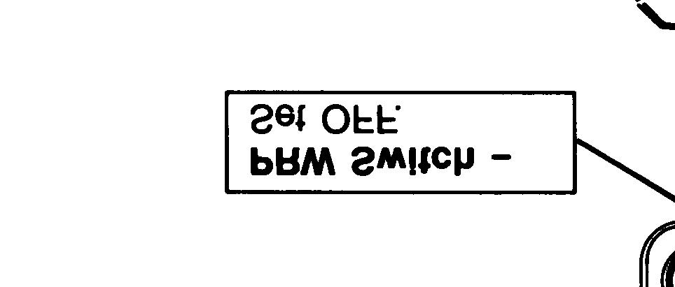
13 2-6. INSTALLATION INSTRUCTIONS. Configurations: 1. SURVEY MODE 2. MONITORING MODE 3. GRR (Vehicle Operation Mode) a. Set PWR switch to OFF. Refer to paragraph 2-4a of the Operator s Manual, TM , and install batteries. b. Attach PROBE to RADIACMETER CABLE. c. Refer to paragraph 2-4d of the Operator s Manual, TM , and perform pre-operational tests. d. For use in configurations 1 and 2 (Survey Mode and Monitoring Mode) refer to paragraph 2-4 and 2-5 of the Operator s Manual, TM Connect STRAP to POUCH and insert RADIACMETER and PROBE into POUCH. For use in configuration 3 (Vehicular Operation) refer to paragraphs 2-7 through 2-10 of this manual. 2-2


 Adjustment of the attenuation factor")

 8 CAPTIVE")


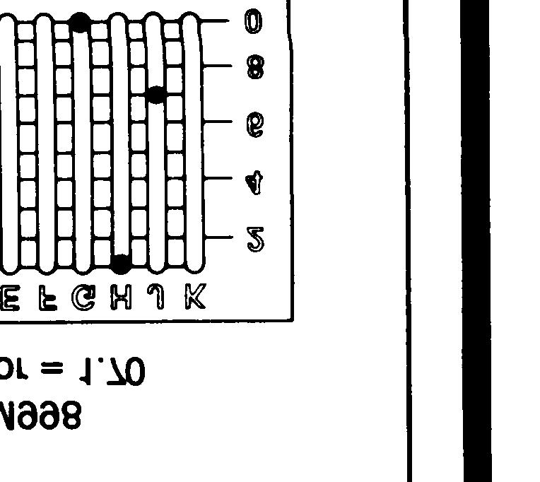
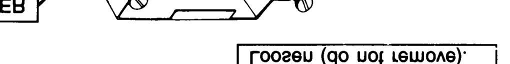
14 2-7. NOTE The attenuation factor of the radiac set is factory set to 10.0, and must be adjusted before the radiac set is installed in a vehicle. Each vehicle has a specific attenuation factor. (Refer to the chart on page 2-5.) Adjustment of the attenuation factor is accomplished by adjustment of SLIDE SWITCH S2 located inside the radiacmeter. a. Set PWR switch to OFF. b. Loosen (do not remove) 8 CAPTIVE SCREWS. c. Slide RADIACMETER HOUSING out of RADIACMETER COVER just far enough to expose SLIDE SWITCH S2. d. SLIDE SWITCH S2 is designed with 10 rows of sliding contacts Iabelled A, B, C, D, E, F, G, H, J, and K. The sliding contact in each row can be positioned at any location 1 through 10 in that row. Rows G, H, and J are used to set the attenuation factor. 2-3

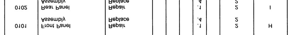
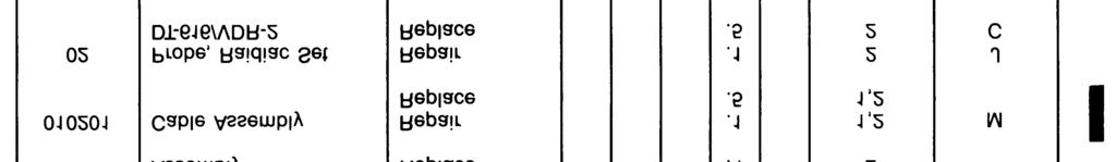
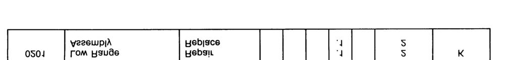
15 NOTE Do not change the setting of the sliding contacts not used in setting the attenuation factor. This will cause the radiac set to function improperly. e. Record the setting of all sliding contacts of SLIDE SWITCH S2 before setting the attenuation factor. f. Refer to the following table and determine the attenuation factor for the vehicle in which the radiac set is being installed. SLIDE SWITCH S2 settings for the vehicles listed in the table are shown on the next page. M1 M2/M3 M60A1/M60A3 M113A1 M151A1/A2 M577A M880 M1008 M g. Press the tip of a ballpoint pen or other similar pointed instrument into the circular recess in the center of the sliding contacts, and move the contacts to the setting determined in step f., above. h. To set an attenuation factor of 23.0, for example, set the sliding contact in row G to 2, row H to 3, and row J to


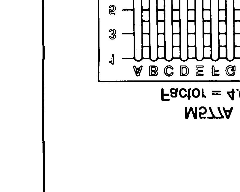

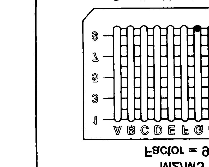
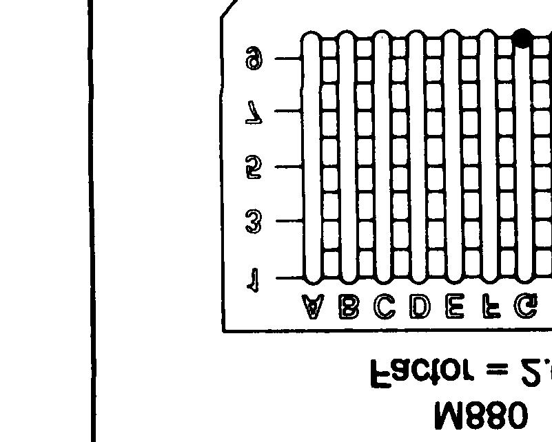
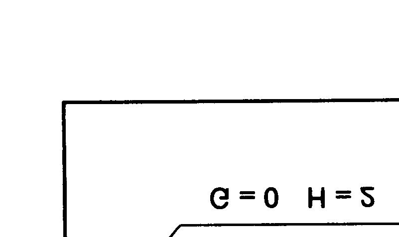
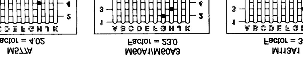
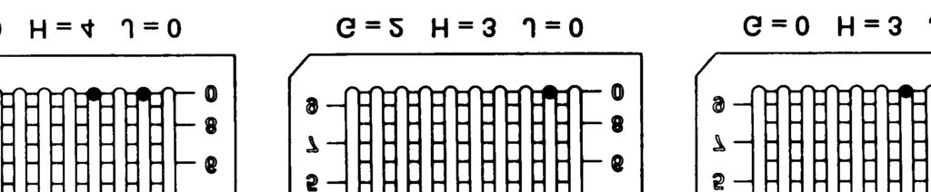
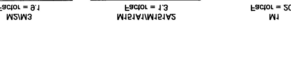
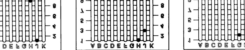
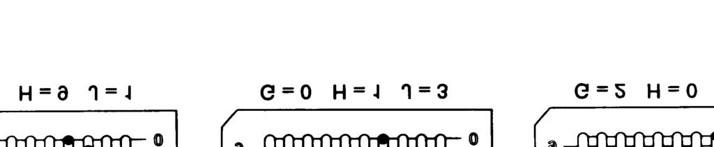
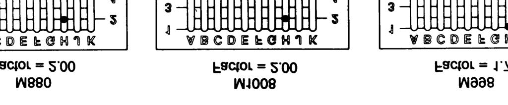
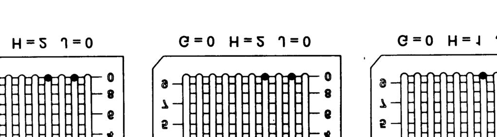
16 SLIDE SWITCH ATTENUATION FACTOR SETTINGS NOTE For vehicle M577A a factor of 4.0 has been set instead of 4.02 because SLIDE SWITCH S2 cannot be set to settings smaller than one-tenth. 2-5 CHANGE 1


17 i. from NOTE If sliding contact settings are made with a resulting value below 1.00, these settings will be ignored by the radiac set and an attenuation factor of 1.00 will be automatically assumed. After setting the sliding contacts in rows G, H, and J, ensure that the other sliding contacts have not moved the settings noted in step e above. j. Set PWR switch to ON, display will indicate RATE. k. Depress and hold ATTEN pushbutton, then depress CLR/TEST pushbutton. l. DISPLAY will indicate attenuation factor set in step g, above. m. If the correct attenuation factor is displayed, set PWR switch to OFF, and proceed to step o, below. n. If the wrong attenuation factor is displayed, an incorrect slide switch setting has been made. Repeat steps a through m above. If the wrong attenuation factor is still displayed, refer the radiac set to the next higher level of maintenance. o. Slide RADIACMETER COVER over RADIAC- METER HOUSING. p. Tighten 8 CAPTIVE SCREWS. 2-6


18 2-8. NOTE An installation kit is required to install the radiac set in a vehicle. Refer to paragraph 1-10 to determine which installation kit is to be used for each type of vehicle. The Mount, Radiac Set MT-6123/VDR-2 is not supplied with each installation kit. a. Set PWR switch to OFF. CAUTION Remove batteries prior to installing radiac set in mount. Radiac set can be damaged if batteries are left in. b. Refer to paragraph 2-4a of the Operator s Manual, TM , and remove all three batteries. c. Replace the battery pouch for future use. cover and store batteries d. Ensure that the probe is securely connected radiacmeter cable. 2-7


19 e. Raise TOP COVER of mount and hinged PROBE POSITIONING FLANGE. f. Insert probe into mount between LEFT WALL and PROBE POSITIONING BRACKET. g. Position probe to fit snugly against PROBE POSI- TIONING TAB, and locate HIGH RANGE DETECTOR ASSEMBLY as shown. h. Position CONVERTER CABLE around probe as shown. i. Connect CONVERTER CABLE PLUG to converter cable receptacle securely. j. Lower PROBE POSITIONING FLANGE. 2-8


20 k. Position coil cord connecting the probe to the radiacmeter to the back of the unit through the opening between the top cover and shelf. l. Position radiacmeter squarely on shelf above probe and center between LOCKING LUGS. m. Close top cover to position radiacmeter against RADIACMETER POSITIONING TAB. n. Tighten RETAINING SCREWS. 2-9


21 2-9. NOTE Installation kits are required to install the radiac set and mount in the vehicles. TM &P contains complete installation instructions. Each installation kit also contains all parts, cables, connectors, and hardware required for installation. A list of these installation kits appears in paragraph The instructions provided with each installation kit will also indicate how the vehicular power cable is to be attached to the radiac set and mount assembly as shown below. a. Set ALM switch to AUD, set PWR switch to ON. b. DISPLAY will indicate three zeros, then dose rate. c. Refer to paragraph 2-4d of the Operator s Manual, TM , and perform pre-operational tests. d. If vehicle headset, check is equipped with that alarm can be an intercom and heard distinctly. 2-10


22 2-10. a. Set PWR switch to OFF. b. Loosen (do not remove) two top cover RETAIN- ING SCREWS. c. Raise TOP COVER and remove radiacmeter. d. Disconnect CONVERTER CABLE from receptacle. e. Remove probe and place radiacmeter and probe in pouch with strap attached. f. Lower TOP COVER and position CONVERTER CABLE within mount. g. Tighten top cover RETAINING SCREWS. 2-11
23 Section Ill. PREVENTIVE MAINTENANCE CHECKS AND SERVICES (PMCS) GENERAL. No preventive maintenance to the radiac set is required at the organizational level. Refer to the Operator s Manual, TM , for PMCS of the radiac set GENERAL Section IV. TROUBLESHOOTING. a. Troubleshooting at the organizational maintenance level requires that you locate faults as quickly as possible. b. Repair or replace a defective unit or component only if authorized to do so. Repairs by organizational maintenance are limited by tools, test equipment, and replacement parts allocated to that level. Refer the problem to a higher level of maintenance if necessary. c. Before using the Troubleshooting Table, paragraph 2-13, check your work order and talk to the equipment operator, if possible, to determine specific fault symptoms. d. The Troubleshooting Table lists common problems that may occur during operation or maintenance of the radiac set. To use the Troubleshooting Table proceed as follows. 1. Locate the problem under the MALFUNCTION heading. 2. Perform the operations listed under the TEST or INSPECTION heading in the order designated. 3. Repair the unit as directed under the CORRECTIVE ACTION heading: e. This Troubleshooting Table cannot list all problems that may occur, or provide all possible procedures to correct the problem. If you cannot locate the problem in the table, or if the problem is not corrected by following the procedures in the table, notify your supervisor TROUBLESHOOTING TABLE. MALFUNCTION TEST OR INSPECTION CORRECTIVE ACTION Table 2-1. Troubleshooting a. DISPLAY IS BLANK AND DARK, RADIAC SET ON, NOT VEHICLE MOUNTED. Replace batteries. (Refer to paragraph 2-4a of Operator s Manual, TM ) b. DISPLAY IS BLANK AND DARK, VEHICLE MOUNTED. Step 1. Check converter cable is connected to radiac set. Connect converter cable as necessary. Step 2. Check radiac set in accordance with paragraph Repair as instructed in paragraph c. DISPLAY FLASHES O DURING OPERATION OR TESTING. Check probe connected to radiacmeter. Connect probe as necessary. d. DISPLAYED ATTENUATION FACTOR DIFFERENT FROM THAT ASSIGNED TO YOUR VEHICLE. Check slide switch S2 is set to correct attenuation factor. (Refer to paragraph 2-7.) Set attenuation factor in accordance with paragraph


24 2-14. TROUBLESHOOTING PROCEDURE: DISPLAY IS BLANK AND DARK, RADIAC SET IS VEHICLE MOUNTED. a. Refer to paragraph 2-10 and remove radiac set from mount. b. Refer to paragraph 2-4a of the Operator s Manual, TM , and install fresh batteries. c. If display remains blank and dark, refer radiac set to a higher level of maintenance. d. If display lights up and indicates dose rate, radiac set is operating normally. Refer to paragraph 2-8 and install the radiac set in mount. Proceed to step e below. e. Set PWR switch to OFF. f. Disconnect VEHICULAR POWER CABLE from VEHICULAR POWER CONVERTER. g. Connect a digital voltmeter to vehicular power cable plug socket terminal A and terminal D. h. If voltmeter indicates 10 to 40 V dc, the power converter is defective, refer to paragraph i. If voltmeter indicates other than in step h, above, the problem is in vehicle power supply. Refer the condition to your supervisor. 2-13
25 Section V. MAINTENANCE PROCEDURES GENERAL. Organizational maintenance of the radiac set is limited to routine cleaning, removal of corrosion, touch-up painting, replacement of the power converter and replacement of shock mounts TOUCH-UP PAINTING INSTRUCTIONS. NOTE Do not brush on touch-up paint to areas not already painted. Do not paint display window or alarm light glass. Lightly sand exterior of painted surfaces with fine sandpaper (Item b, Appendix C) to remove rust and corrosion. Protect base metal from further corrosion by brushing on two thin coats of paint. Refer to TB (Field Instructions for Painting and Preserving Electronics Command Equipment). 2-14

26 2-17. REPLACEMENT OF VEHICLE POWER CONVERTER. a. Refer to paragraph 2-10 and remove radiac set from mount. b. Remove cable clamp and retain along with hardware. c. Remove 2 mounting screws and associated washers and retain. d. Replace Vehicle Power Converter using existing hardware. e. Replace cable clamp. 2-15
27 2-18. REPLACEMENT OF SHOCK MOUNT. a. Refer to paragraph 2-10 and remove radiac set from mount. b. Remove top mounting screw and associated washers from shock mount and retain. c. Remove 2 bottom nuts and associated washers and lift out 2 flat head screws (retain all hardware). d. Replace shock mount and reinstall using existing hardware and shock mount spacer. 2-16
28 Section VI. PREPARATION FOR STORAGE OR SHIPMENT PACKING FOR SHIPMENT. CAUTION Batteries must be removed prior to shipment. Prolonged storage of radiac set with batteries installed may damage equipment. a. Refer to paragraph 2-4a of the Operator s Manual, TM , and remove batteries. b. Refer to paragraph 2-4b of TM and install the radiacmeter and probe in the pouch and close pouch prior to shipment PREPARATION FOR STORAGE. a. Refer to paragraph 2-4d of the Operator s Manual, TM , and perform pre-operational tests to ensure that radiac set is operational. b. Refer to paragraph 2-4a of the Operator s Manual, TM , and remove batteries. c. Refer to paragraph 2-4b of Manual TM , and install radiacmeter in the pouch and close pouch prior to storage. 2-17/(2-18 Blank)
29 APPENDIX A REFERENCES A-1. SCOPE This appendix lists forms and publications that are referenced in this manual or that contain information applicable to the operation and organizational maintenance of the Radiac Set AN/VDR-2. A-2. FORMS DA Form Standard Form 361 Standard Form 364 Standard Form 368 Recommended Changes to Equipment Technical Manuals Discrepancy in Shipment Report (DISREP) Report of Discrepancy (ROD) Quality Deficiency Report A-3. PUBLICATIONS DA Pam FM 3-12 TB DA Pam TM TM TM Consolidated Index of Army Publications and Blank Forms Operational Aspects of Radiolocial Defense Field Instructions for Painting and Preserving Communications- Electronics Equipment The Army Maintenance Management System (TAMMS) Procedures for Destruction of Electronics Materiel to Prevent Enemy Use (Electronics Command) Administrative Storage of Equipment Operator s Manual: Radiac Set AN/VDR-2 TM &P Organizational Maintenance Manual Including Repair Parts and Special Tools List: Radiac Set Installation Kits For Using Vehicles A-1/(A-2 Blank) CHANGE 1
30 APPENDIX B MAINTENANCE ALLOCATION CHART Section I. INTRODUCTION B-1. GENERAL This appendix provides a summary of the maintenance operations for the Radiac Set. It authorizes categories of maintenance for specific maintenance functions on repairable items and components and the tools and equipment required to perform each function. This appendix may be used as an aid in planning maintenance operations. B-2. MAINTENANCE FUNCTION Maintenance functions will be limited to and defined as follows: a. INSPECT. To determine the serviceability of an item by comparing its physical, mechanical, and/or electrical characteristics with established standards through examination. b. TEST. To verify serviceability and to detect incipient failure by measuring the mechanical or electrical characteristics of an item and comparing those characteristics with prescribed standards. c. CALIBRATE. To determine and cause corrections to be made or to be adjusted on instruments or test measuring and diagnostic equipments used in precision measurement. Consists of comparisons of two instruments, one of which is a certified standard of known accuracy, to detect and adjust any discrepancy in the accuracy of the instrument being compared. d. INSTALL. The act of emplacing, seating, or fixing into position an item, part, module (component or assembly) in a manner to allow the proper functioning of the equipment or system. e. ADJUST. To maintain, within prescribed limits, by bringing into proper or exact position or by setting the operating characteristics to the specified parameters. f. REPAIR. The application of maintenance services (inspect, test, service, adjust, align, calibrate, replace) or other maintenance actions (welding, grinding, riveting, straightening, facing, remachining, or resurfacing) to restore serviceability to an item by correcting specific damage, fault, malfunction, or failure in a part, sub-assembly, module (component or assembly), end item, or system. B-3. COLUMN ENTRIES a. COLUMN 1, GROUP NUMBER. Column 1 lists group numbers, the purpose of which is to identify components, assemblies, sub-assemblies and modules with the next higher assembly. b. COLUMN 2, COMPONENT/ASSEMBLY. Column 2 contains the noun names of components, assemblies, sub-assemblies, and modules for which maintenance is authorized. c. COLUMN 3, MAINTENANCE FUNCTIONS. Column 3 lists the functions to be performed on the item listed in Column 2. When the items are listed without maintenance functions, it is solely for the purpose of having the group numbers in the MAC and RPSTL coincide. d. COLUMN 4, MAINTENANCE CATEGORY. Column 4 specifies, by the listing of a work time figure in the appropriate sub-columns, the lowest level of maintenance authorized to perform the function listed in Column 3. This figure represents the active time required to perform that maintenance function at the indicated category of maintenance. If the number or complexity of the task within the listed maintenance function varies at different maintenance categories, appropriate work time figures will be shown for each category. The number of taskhours specified by the work time figure represents the average time required to restore an item (assembly, sub-assembly, component, module, end item, or system) to a serviceable condition under typical field conditions. B-1
31 This time includes preparation time, troubleshooting time, and quality assurance/quality control time in addition to the time required to perform the specific tasks identified for the maintenance functions authorized in the maintenance allocation chart. Sub-columns of Column 4 are as follows: C - Operator/Crew O - Organizational F - Direct Support H - General Support D - Depot e. COLUMN 5, TOOLS AND EQUIPMENT. Column 5 specifies by the code, those common tool sets (not individual tools) and special tools, test, and support equipment to perform the designated function. f. COLUMN 6, REMARKS. Column 6 contains an alphabetic code which leads to the remark in Section IV. Remarks, which is pertinent to the item opposite the particular code. B-4. TOOL AND TEST EQUIPMENT REQUIREMENTS (SECTION Ill) a. TOOLS OR TEST EQUIPMENT REFERENCE CODE. The numbers in this column coincide with the numbers used in the tools and equipment column of the MAC. The numbers indicate the applicable tool or test equipment for the maintenance functions. b. MAINTENANCE CATEGORY. The codes in this column indicate the maintenance category allocated to the tool or test equipment. c. NOMENCLATURE. This column lists the noun name and nomenclature of the tools and test equipment required to perform the maintenance functions. d. NATIONAL/NATO STOCK NUMBER. This column lists the National/NATO stock number of the specific tool or test equipment. e. TOOL NUMBER. This column lists the manufacturer s part of the tool followed by the Federal Supply Code for manufacturers (5 digit number) in parentheses. B-5. REMARKS (SECTION IV) a. REFERENCE CODE. This code refers to the appropriate item in Section II, Column 6. b. REMARKS. This column provides the required explanatory information necessary to clarify items appearing in Section Il. B-2

32 Section IIA. MAINTENANCE ALLOCATION CHART FOR RADIAC SET, AN/VDR-2 B-3 CHANGE 1
33 Section IIB. MAINTENANCE ALLOCATION CHART FOR MOUNT, MT-6123/VDR-2 B-4
34 Section IIIA. TOOL AND TEST EQUIPMENT REQUIREMENTS FOR RADIAC SET AN/VDR-2 Section IIIB. TOOL AND TEST EQUIPMENT REQUIREMENTS FOR MOUNT, MT-6123/VDR-2 B-5
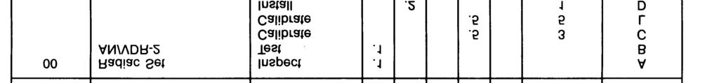
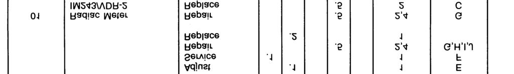
35 Section IVA. REMARKS RADIAC SET AN/VDR-2 REF. CODE REMARKS A B C D E F G H I J K L M Visual Inspection. Operational Test Using Bite. Calibration of Radiacmeter and Probe Using AN/UDM-2. Install Radiac Set in Vehicle. Set Attenuation Factor Switch. Service by Replacing Batteries (3 Each 9 Volts). Repair by Replacing Front Panel Assembly, Rear Panel Assembly, PCBs. Repair by Replacing Front Panel Assembly Gasket. Repair by Replacing Rear Panel Assembly Gasket, Power Supply Board, Battery Housing Assembly. Repair by Replacing High Range Detector Assembly, Low Range Assembly. Repair by Replacement of Mylar Window Assembly. Calibration Using AN/UDM-1A for Health/Safety Applications. Repair by Replacing Cable Assembly. Section IVB. REMARKS MOUNT, MT-6123/VDR-2 REF. CODE REMARKS A B C Visual Inspection. Repair by Replacing the Vehicular Power Converter, Shock Mounts. Test Output Using AN/PSM-45. B-6 CHANGE 1 PIN:
36 APPENDIX C EXPENDABLE SUPPLIES AND MATERIALS LIST Section I. INTRODUCTION C-1. SCOPE This appendix lists expendable supplies and materials you will need to operate and maintain the radiac set. These are authorized to you by CTA Expendable Items (Except Medical, Class V, Repair Parts, and Heraldic Items). C-2. EXPLANATION OF COLUMNS a. COLUMN 1, ITEM NUMBER. This number is assigned to the entry in the listing and is referenced in the narrative instructions to identify the material (e.g., Use cleaning compound, Item 5, Appendix D ). b. COLUMN 2, LEVEL. This column identifies the lowest level of maintenance that requires the listed item. C Operator/Crew O Organizational Maintenance F Direct Support Maintenance H General Support Maintenance D Depot c. COLUMN 3, NATIONAL STOCK NUMBER. This is the national stock number assigned to the item used to request or requisition the item. d. COLUMN 4, DESCRIPTION. Indicates the federal item name and, if required, a description to identify the item. The last line for each item indicates the part number followed by the Federal Supply Code for Manufacturer (FSCM), in parentheses, if applicable. e. COLUMN 5, UNIT OF MEASURE (U/M). Indicates the measure used in performing the actual maintenance function. This measure is expressed by a two-character alphabetical abbreviation (e.g., ea, in, pr). If the unit of measure differs from the unit of issue: requisition the lowest unit of issue that will satisfy your requirements. Section Il. EXPENDABLE SUPPLIES AND MATERIALS LIST (1) (2) (3) (4) (5) UNIT ITEM NATIONAL DESCRIPTION OF NO. LEVEL STOCK NO. PART NO. AND FSCM MEAS Battery, Dry Cold-Weather, BA-3090 ea 2 0 Cleaning Compound ea Cleaning Cloth, Lint Free yd Inch Bristled Brush ea 5 0 Paint pt Sandpaper, No. 000 sh C-1/(C-2 Blank)
37 By Order of the Secretary of the Army: Official: CARL E. VUONO General, United States Army Chief of Staff R.L. DILWORTH Brigadier General, United States Army The Adjutant General DISTRIBUTION: To be distributed in accordance with DA Form literature requirements for AN/VDR-2.
38
39
40
41 THE METRIC SYSTEM AND EQUIVALENTS
42 PIN:
TECHNICAL MANUAL OPERATOR S, ORGANIZATIONAL, DIRECT SUPPORT, AND GENERAL SUPPORT MAINTENANCE MANUAL
 TECHNICAL MANUAL TM 11-6660-200-14 OPERATOR S, ORGANIZATIONAL, DIRECT SUPPORT, AND GENERAL SUPPORT MANUAL OPERATING INSTRUCTIONS PAGE 2-1 OPERATOR PAGE 3-1 ORGANIZATIONAL PAGE 4-1 DIRECT AND GENERAL SUPPORT
TECHNICAL BULLETIN VIS
 ARMY TB 11-5830-263-20-1 MARINE CORPS MI 08953A-35/26 TECHNICAL BULLETIN VIS INSTALLATION INSTRUCTIONS FOR INTERCOMMUNICATION SET, VEHICULAR AN/VIC-3(V)1 (NSN 5830-01-395-4177) (EIC: NA) IN A TANK, COMBAT,
OPERATOR AND ORGANIZATIONAL MAINTENANCE MANUAL SIMULATOR, RADAR SIGNAL SM-756/APR-44(V) (NSN )
 (NSN )") TM 11-6940-214-12 OPERATOR AND ORGANIZATIONAL MAINTENANCE MANUAL TABLE OF CONTENTS PAGE i EQUIPMENT DESCRIPTION PAGE 1-4 OPERATOR'S CONTROLS PAGE 2-1 PREVENTIVE MAINTENANCE PAGE 2-3 OPERATION PAGE 2-17
TM 11-6940-214-12 OPERATOR AND ORGANIZATIONAL MAINTENANCE MANUAL TABLE OF CONTENTS PAGE i EQUIPMENT DESCRIPTION PAGE 1-4 OPERATOR'S CONTROLS PAGE 2-1 PREVENTIVE MAINTENANCE PAGE 2-3 OPERATION PAGE 2-17
OPERATOR'S, ORGANIZATIONAL, DIRECT SUPPORT, AND GENERAL SUPPORT MAINTENANCE MANUAL FOR MULTIPLEXER SET AN/FCC-97 (NSN )
") ARMY TM 11-5805-694-14 AIR FORCE TO 31W2-4-287-1 OPERATOR'S, ORGANIZATIONAL, DIRECT SUPPORT, AND GENERAL SUPPORT MAINTENANCE MANUAL FOR MULTIPLEXER SET AN/FCC-97 (NSN 5805-01-0308) This copy is a reprint
ARMY TM 11-5805-694-14 AIR FORCE TO 31W2-4-287-1 OPERATOR'S, ORGANIZATIONAL, DIRECT SUPPORT, AND GENERAL SUPPORT MAINTENANCE MANUAL FOR MULTIPLEXER SET AN/FCC-97 (NSN 5805-01-0308) This copy is a reprint
DISTRIBUTION STATEMENT A: Approved for public release; distribution is unlimited. HEADQUARTERS, DEPARTMENT OF THE ARMY 31 AUGUST 1994
 TECHNICAL MANUAL OPERATOR'S AND UNIT- MAINTENANCE MANUAL 20K GALLON WATER STORAGE AND DISTRIBUTION SYSTEM MODEL 2OKWSDS (NSN: 4320-01-382-2684) (EIC: ZIN) HOW TO USE THIS MANUAL iii EQUIPMENT DESCRIPTION
TECHNICAL MANUAL OPERATOR, UNIT, AND DIRECT SUPPORT MAINTENANCE MANUAL (INCLUDING REPAIR PARTS AND SPECIAL TOOLS LIST)
") TECHNICAL MANUAL OPERATOR, UNIT, AND DIRECT SUPPORT MAINTENANCE MANUAL (INCLUDING REPAIR PARTS AND SPECIAL TOOLS LIST) TANK, FABRIC, COLLAPSIBLE, WATER, 3,000 AND 5,000 GALLONS, SEMI-TRAILER MOUNTED 3,000
TECHNICAL MANUAL OPERATOR, UNIT, AND DIRECT SUPPORT MAINTENANCE MANUAL (INCLUDING REPAIR PARTS AND SPECIAL TOOLS LIST) TANK, FABRIC, COLLAPSIBLE, WATER, 3,000 AND 5,000 GALLONS, SEMI-TRAILER MOUNTED 3,000
HEADQUARTERS, DEPARTMENT OF THE ARMY
 *TM 10-4610-234-13 OPERATOR S, UNIT AND DIRECT SUPPORT MAINTENANCE MANUAL FOR 40,000 GALLON WATER DISTRIBUTION SYSTEM NSN 4610-01-114-1451 DISTRIBUTION STATEMENT A: Approved for public release; distribution
OPERATOR, ORGANIZATIONAL, DS, GS, AND DEPOT MAINTENANCE MANUAL INCLUDING REPAIR PARTS AND SPECIAL TOOL LISTS
 DEPARTMENT OF THE ARMY TECHNICAL MANUAL OPERATOR, ORGANIZATIONAL, DS, GS, AND DEPOT MAINTENANCE MANUAL INCLUDING REPAIR PARTS AND SPECIAL TOOL LISTS WIND MEASURING SET AN/PMQ-3A (NSN 6660-515-4339) This
MANUAL TELEPHONE SWITCHBOARD SB-993/GT
 TM 11-5805-294-12 OPERATOR S AND ORGANIZATIONAL MAINTENANCE MANUAL 2-0 MANUAL TELEPHONE SWITCHBOARD SB-993/GT (NSN 5805-00-708-2202) HEADQUARTERS, DEPARTMENT OF THE ARMY 8 SEPTEMBER 1983 SAFETY STEPS TO
ARMY TM AIR FORCE TO 35C MARINE CORPS TM 10155A-13/1
 OPERATOR S, UNIT, AND DIRECT SUPPORT MAINTENANCE MANUAL OPERATING INSTRUCTIONS 2-1 OPERATOR TROUBLESHOOTING 3-3 UNIT LEVEL PMCS 4-7 UNIT LEVEL TROUBLESHOOTING 4-12 UNIT MAINTENANCE PROCEDURES 4-27 DIRECT
MODIFICATION WORK ORDER MODIFICATION OF ANTENNA GROUP OE-254/GRC (NSN )
") LIMITED URGENT MWO effective date is 1 February 1991 and completion date is 1 August 1991. MODIFICATION WORK ORDER MWO 11-5985-357-30-1 MODIFICATION OF ANTENNA GROUP OE-254/GRC (NSN 5985-01-063-1574) Headquarters,
LIMITED URGENT MWO effective date is 1 February 1991 and completion date is 1 August 1991. MODIFICATION WORK ORDER MWO 11-5985-357-30-1 MODIFICATION OF ANTENNA GROUP OE-254/GRC (NSN 5985-01-063-1574) Headquarters,
Distribution Statement A: Approved for public release; distribution is unlimited.
 TECHNICAL MANUAL OPERATOR'S, UNIT, DIRECT SUPPORT AND GENERAL SUPPORT MAINTENANCE MANUAL OPERATING INSTRUCTIONS 2-1 OPERATOR PREVENTIVE 2-5 MAINTENANCE CHECKS AND SERVICES (PMCS) OPERATOR 3-1 TROUBLESHOOTING
TEST SET, TRANSISTOR TS-1836D/U NSN
 TECHNICAL MANUAL OPERATOR S, ORGANIZATIONAL, DIRECT SUPPORT AND GENERAL SUPPORT MAINTENANCE MANUAL TEST SET, TRANSISTOR TS-1836D/U NSN 6625-00-138-7320 This copy is a reprint which includes current pages
TECHNICAL BULLETIN REPAIR OF DISPLAY/KEYPAD ASSEMBLY (A ) WITH REPAIR KIT A (NSN ) (EIC: N/A)
 WITH REPAIR KIT A (NSN ) (EIC: N/A)") TECHNICAL BULLETIN TB 11-5820-890-30-4 REPAIR OF DISPLAY/KEYPAD ASSEMBLY (A3266120-1) WITH REPAIR KIT A3210962-1 (NSN 5895-01-484-6837) (EIC: N/A) Approved for public release; distribution is unlimited.
TECHNICAL BULLETIN TB 11-5820-890-30-4 REPAIR OF DISPLAY/KEYPAD ASSEMBLY (A3266120-1) WITH REPAIR KIT A3210962-1 (NSN 5895-01-484-6837) (EIC: N/A) Approved for public release; distribution is unlimited.
Approved for public release. Distribution is unlimited.
 TECHNICAL MANUAL UNIT, INTERMEDIATE DIRECT SUPPORT AND INTERMEDIATE GENERAL SUPPORT MAINTENANCE INSTRUCTIONS BILGE / BALLAST PUMP FOR LANDING CRAFT UTILITY (LCU ) NSN 1905-01-154-1191 INTRODUCTION 1-1
TECHNICAL MANUAL OPERATOR S AND UNIT MAINTENANCE MANUAL INCLUDING REPAIR PARTS AND SPECIAL TOOLS LIST FOR
 TECHNICAL MANUAL OPERATOR S AND UNIT MAINTENANCE MANUAL INCLUDING REPAIR PARTS AND SPECIAL TOOLS LIST FOR SHOP EQUIPMENT CONTACT MAINTENANCE (SECM) MOUNTED ON HIGH MOBILITY MULTI PURPOSE WHEELED VEHICLE
TECHNICAL MANUAL OPERATOR, UNIT, AND DIRECT SUPPORT MAINTENANCE MANUAL (INCLUDING REPAIR PARTS AND SPECIAL TOOLS LIST)
") TECHNICAL MANUAL OPERATOR, UNIT, AND DIRECT SUPPORT MAINTENANCE MANUAL (INCLUDING REPAIR PARTS AND SPECIAL TOOLS LIST) POWER UNIT, 2 1/2 TON DIESEL ENGINE DRIVEN, TRAILER MOUNTED, 60 kw, 50/60 Hz, PU-805
TECHNICAL MANUAL OPERATOR, UNIT, AND DIRECT SUPPORT MAINTENANCE MANUAL (INCLUDING REPAIR PARTS AND SPECIAL TOOLS LIST) POWER UNIT, 2 1/2 TON DIESEL ENGINE DRIVEN, TRAILER MOUNTED, 60 kw, 50/60 Hz, PU-805
ARMY TM NAVY EE161-DM-OPI-010/E154UGC74 AIR FORCE
 ARMY TM 11-5815-602-10 NAVY AIR FORCE OPERATOR S MANUAL EQUIPMENT DESCRIPTION Page 1-5 OPERATING INSTRUCTIONS Page 2-0 DESCRIPTION OF CONTROLS Page 2-1 PREVENTIVE MAINTENANCE CHECKS AND SERVICES (PMCS)
TECHNICAL MANUAL UNIT AND DIRECT SUPPORT MAINTENANCE MANUAL (INCLUDING REPAIR PARTS AND SPECIAL TOOLS LIST) FOR LONG RANGE SNIPER RIFLE (LRSR), M107
 FOR LONG RANGE SNIPER RIFLE (LRSR), M107") TECHNICAL MANUAL UNIT AND DIRECT SUPPORT MAINTENANCE MANUAL (INCLUDING REPAIR PARTS AND SPECIAL TOOLS LIST) FOR LONG RANGE SNIPER RIFLE (LRSR), M107 (NSN 1005-01-469-2133) 6 DISTRIBUTION STATEMENT A Approved
TECHNICAL MANUAL UNIT AND DIRECT SUPPORT MAINTENANCE MANUAL (INCLUDING REPAIR PARTS AND SPECIAL TOOLS LIST) FOR LONG RANGE SNIPER RIFLE (LRSR), M107 (NSN 1005-01-469-2133) 6 DISTRIBUTION STATEMENT A Approved
OPERATOR, UNIT, AND DIRECT SUPPORT MAINTENANCE MANUAL INCLUDING REPAIR PARTS AND SPECIAL TOOLS LIST for TELESCOPE, STRAIGHT: M145 ( )
") OPERATOR, UNIT, AND DIRECT SUPPORT MAINTENANCE MANUAL INCLUDING REPAIR PARTS AND SPECIAL TOOLS LIST for TELESCOPE, STRAIGHT: M145 (1240-01-411-6350) Distribution Statement A Approved for public release;
OPERATOR, UNIT, AND DIRECT SUPPORT MAINTENANCE MANUAL INCLUDING REPAIR PARTS AND SPECIAL TOOLS LIST for TELESCOPE, STRAIGHT: M145 (1240-01-411-6350) Distribution Statement A Approved for public release;
TECHNICAL MANUAL OPERATOR'S, UNIT, DIRECT SUPPORT, AND GENERAL SUPPORT MAINTENANCE MANUAL
 TECHNICAL MANUAL OPERATOR'S, UNIT, DIRECT SUPPORT, AND GENERAL SUPPORT MAINTENANCE MANUAL AIR CONDITIONER, HORIZONTAL, COMPACT, 36,000 BTU/HR, MULTI-POWER INPUT 208V, 3 PHASE, 50/60/400 HZ MODEL MH-40-MP
HEADQUARTERS, DEPARTMENT OF THE ARMY
 *ARMY TM 10-5410-284-13&P MARINE CORPS TM 10602A-13&P OPERATOR S, UNIT, AND DIRECT SUPPORT MAINTENANCE MANUAL, INCLUDING REPAIR PARTS AND SPECIAL TOOLS LIST (RPSTL) FOR THE NSN 8340-01-456-3637 (GREEN)
Distribution Statement A: Approved for public release; distribution is unlimited.
 TECHNICAL MANUAL OPERATOR'S, UNIT, DIRECT SUI'PORT AND GENERAL SUIPPORT MAINTENANCE MANUAL FOR TACTICAL WATER DISTRIBUTION SYSTEM MODEL TWDS20 NSN: 4320-01-361-9232 HOW TO USE THIS MANUAL EQUIPMENT DESCRIPTION
UNIT LEVEL MAINTENANCE HANDBOOK SINCGARS ICOM GROUND RADIOS GROUND ICOM RADIO SETS
 TM 11-5820-890-20-3 UNIT LEVEL MAINTENANCE HANDBOOK SINCGARS ICOM GROUND RADIOS INTRODUCTION PAGE 1-1 MANPACK RADIO PAGE 2-1 VEHICUlAR RADIOS PAGE 3-1 CABLE SCHEMATICS PAGE 4-1 SELECTED GRAPHICS PAGE 5-1
HEADQUARTERS, DEPARTMENT OF THE ARMY
 TECHNICAL MANUAL OPERATOR S, ORGANIZATIONAL, DIRECT SUPPORT, AND GENERAL SUPPORT MAINTENANCE MANUAL (INCLUDING REPAIR PARTS AND SPECIAL TOOLS LIST) FOR TRAILER, CARGO: 1-1/2-TON, 2-WHEEL, M105A3 NSN 2330-01-452-1218
AIR CONDITIONER HORIZONTAL, COMPACT, 9,000 BTU/HR, 115 VOLT SINGLE PHASE 50/60 HERTZ PART NO. S8450-9KC-1H (NSN ) (EIC: N/A)
 (EIC: N/A)") TECHNICAL MANUAL OPERATOR S, UNIT, DIRECT SUPPORT AND GENERAL SUPPORT MAINTENANCE MANUAL INCLUDING REPAIR PARTS AND SPECIAL TOOLS LIST FOR AIR CONDITIONER HORIZONTAL, COMPACT, 9,000 BTU/HR, 115 VOLT SINGLE
TECHNICAL MANUAL OPERATOR S, UNIT, DIRECT SUPPORT AND GENERAL SUPPORT MAINTENANCE MANUAL INCLUDING REPAIR PARTS AND SPECIAL TOOLS LIST FOR AIR CONDITIONER HORIZONTAL, COMPACT, 9,000 BTU/HR, 115 VOLT SINGLE
TM &P MARCH 1983 TECHNICAL MANUAL HEADQUARTERS, DEPARTMENT OF THE ARMY PAGE 2-12 PAGE 3-1 PAGE 3-9 PAGE B-1
 TECHNICAL MANUAL TM 9-1005-309-23&P ORGANIZATIONAL AND DIRECT SUPPORT MAINTENANCE MANUAL (INCLUDING REPAIR PARTS AND SPECIAL TOOLS LIST) FOR SUBMACHINE GUN, 5.56-MM: PORT, FIRING, M231 (1005-01-081-4582)
*TM &P AIRFORCE T.O. 14D NAVSEA SS400-AY-MMO-010 MARINE CORPS TM &P
 *TM 10-1670-305-23&P AIRFORCE T.O. 14D2-11-1 NAVSEA SS400-AY-MMO-010 MARINE CORPS TM 1670-23&P TECHNICAL MANUAL UNIT AND DIRECT SUPPORT MAINTENANCE MANUAL (INCLUDING REPAIR PARTS AND SPECIAL TOOLS LISTS)
TECHNICAL MANUAL OPERATOR, UNIT, DIRECT SUPPORT AND GENERAL SUPPORT MAINTENANCE MANUAL (INCLUDING REPAIR PARTS AND SPECIAL TOOLS LISTS)
") *TM 9-6115-646-14&P TECHNICAL MANUAL OPERATOR, UNIT, DIRECT SUPPORT AND GENERAL SUPPORT MAINTENANCE MANUAL (INCLUDING REPAIR PARTS AND SPECIAL TOOLS LISTS) POWER UNIT PU-495A/G (NSN 6115-00-394-9575) AND
*TM 9-6115-646-14&P TECHNICAL MANUAL OPERATOR, UNIT, DIRECT SUPPORT AND GENERAL SUPPORT MAINTENANCE MANUAL (INCLUDING REPAIR PARTS AND SPECIAL TOOLS LISTS) POWER UNIT PU-495A/G (NSN 6115-00-394-9575) AND
ANCILLARY EQUIPMENT FOR: PERSONNEL TROOP PARACHUTE SYSTEM
 *TM 10-1670-299-20&P TO 14D1-2-470-2 NAVAIR 13-1-41 UNIT MAINTENANCE MANUAL, INCLUDING REPAIR PARTS AND SPECIAL TOOLS LIST (RPSTL) FOR ANCILLARY EQUIPMENT FOR: PERSONNEL TROOP PARACHUTE SYSTEM CASE, PARACHUTISTS,
CONTAINERIZED CHAPEL (CC) NSN
 NSN") TECHNICAL MANUAL OPERATOR S AND UNIT MAINTENANCE MANUAL (INCLUDING REPAIR PARTS AND SPECIAL TOOLS LIST) CONTAINERIZED CHAPEL (CC) NSN 9925-01-481-5136 DISTRIBUTION STATEMENT A Approved for public release;
TECHNICAL MANUAL OPERATOR S AND UNIT MAINTENANCE MANUAL (INCLUDING REPAIR PARTS AND SPECIAL TOOLS LIST) CONTAINERIZED CHAPEL (CC) NSN 9925-01-481-5136 DISTRIBUTION STATEMENT A Approved for public release;
TECHNICAL MANUAL OPERATOR AND UNIT MAINTENANCE MANUAL (INCLUDING REPAIR PARTS AND SPECIAL TOOLS LIST)
") TECHNICAL MANUAL OPERATOR AND UNIT MAINTENANCE MANUAL (INCLUDING REPAIR PARTS AND SPECIAL TOOLS LIST) TANK, FABRIC, COLLAPSIBLE; WATER STORAGE, 20,000 AND 50,000 GALLONS 20,000 GALLONS MODEL GTA-20KW NSN
TECHNICAL MANUAL OPERATOR AND UNIT MAINTENANCE MANUAL (INCLUDING REPAIR PARTS AND SPECIAL TOOLS LIST) TANK, FABRIC, COLLAPSIBLE; WATER STORAGE, 20,000 AND 50,000 GALLONS 20,000 GALLONS MODEL GTA-20KW NSN
SPACE HEATER SMALL (NSN )
") TECHNICAL MANUAL OPERATOR S AND UNIT MAINTENANCE MANUAL (INCLUDING REPAIR PARTS AND SPECIAL TOOLS LISTS) SPACE HEATER SMALL (NSN 4520-01-478-9207) DISTRIBUTION STATEMENT A Approved for public release;
TECHNICAL MANUAL OPERATOR S AND UNIT MAINTENANCE MANUAL (INCLUDING REPAIR PARTS AND SPECIAL TOOLS LISTS) SPACE HEATER SMALL (NSN 4520-01-478-9207) DISTRIBUTION STATEMENT A Approved for public release;
DISTRIBUTION STATEMENT A: Approved for public release; distribution is unlimited.
 TECHNICAL MANUAL OPERATOR'S UNIT, DIRECT SUPPORT AND GENERAL SUPPORT MAINTENANCE MANUAL FOR CONTAINER, REFRIGERATED 20 FEET MODEL KR020A180G NSN: 8145-01-388-4966 Operating Instructions 2-1 Operator Maintenance
TM ARMY AH-64A HELICOPTER HELLFIRE MISSILE EQUIPMENT AVIATION INTERMEDIATE MAINTENANCE MANUAL TECHNICAL MANUAL
 TECHNICAL MANUAL AVIATION INTERMEDIATE MAINTENANCE MANUAL ARMY AH-64A HELICOPTER HELLFIRE MISSILE EQUIPMENT This copy is a reprint which includes current pages from Changes 1 through 6. HEADQUARTERS, DEPARTMENT
TM &P TECHNICAL MANUAL INTRODUCTION 1-1 OPERATOR, UNIT, AND DIRECT SUPPORT MAINTENANCE (INCLUDING REPAIR PARTS AND SPECIAL TOOLS LIST)
") TECHNICAL MANUAL OPERATOR, UNIT, AND DIRECT SUPPORT MAINTENANCE (INCLUDING REPAIR PARTS AND SPECIAL TOOLS LIST) FOR WATER QUALITY ANALYSIS SET PREVENTIVE MEDICINE NSN 6630-01-367-9402 (EIC) ZGF INTRODUCTION
TECHNICAL MANUAL OPERATOR, UNIT, AND DIRECT SUPPORT MAINTENANCE (INCLUDING REPAIR PARTS AND SPECIAL TOOLS LIST) FOR WATER QUALITY ANALYSIS SET PREVENTIVE MEDICINE NSN 6630-01-367-9402 (EIC) ZGF INTRODUCTION
CARRIER, PERSONNEL, FULL TRACKED, ARMORED, M113A CARRIER, COMMAND POST, LIGHT TRACKED, M577A
 OPERATOR S MANUAL CARRIER, PERSONNEL, FULL TRACKED, ARMORED, M113A2 2350-01-068-4077 CARRIER, COMMAND POST, LIGHT TRACKED, M577A2 2350-01-068-4089 CARRIER, MORTAR, 107-MM, M30; SELF-PROPELLED, M106A2 2350-01-069-6931
Approved for public release. Distribution is unlimited.
 TM 55-1 905-223-24-11 TECHNICAL MANUAL UNIT, INTERMEDIATE DIRECT SUPPORT AND INTERMEDIATE GENERAL SUPPORT MAINTENANCE INSTRUCTIONS MARINE SANITATION SYSTEM FOR LANDING CRAFT UTILITY (LCU) NSN 1905-01-154-1191
TM * HEADQUARTERS, DEPARTMENT OF THE ARMY DIRECT SUPPORT AND GENERAL SUPPORT MAINTENANCE
 * DIRECT SUPPORT AND GENERAL SUPPORT MAINTENANCE TRUCK, FORKLlFT, DED PNEUMATIC TIRE, 10,000 LB. CAPACITY ROUGH TERRAIN, ARTICULATED FRAME STEER (DRESSER INDUSTRIES MODEL M10A, MHE 236) (NSN 3930-01-054-3833)
OPERATOR S MANUAL FOR MULTIPLE INTEGRATED LASER ENGAGEMENT SYSTEM (MILES) SIMULATOR SYSTEM, FIRING LASER: M83 (NSN ) FOR
 SIMULATOR SYSTEM, FIRING LASER: M83 (NSN ) FOR") Supersedes copy dated 18 October 1984 OPERATOR S MANUAL FOR MULTIPLE INTEGRATED LASER ENGAGEMENT SYSTEM (MILES) SIMULATOR SYSTEM, FIRING LASER: M83 (NSN 1265-01-158-4560) FOR M2/M3 FIGHTING VEHICLES DISTRIBUTION
Supersedes copy dated 18 October 1984 OPERATOR S MANUAL FOR MULTIPLE INTEGRATED LASER ENGAGEMENT SYSTEM (MILES) SIMULATOR SYSTEM, FIRING LASER: M83 (NSN 1265-01-158-4560) FOR M2/M3 FIGHTING VEHICLES DISTRIBUTION
TECHNICAL MANUAL OPERATOR'S MANUAL VIS INTERCOMMUNICATION SET, VEHICULAR AN/VIC-3(V), INCLUDING:
, INCLUDING:") TECHNICAL MANUAL OPERATOR'S MANUAL VIS INTERCOMMUNICATION SET, VEHICULAR AN/VIC-3(V), INCLUDING: Control, Indicator CD-82/VRC (NSN 5895-01-382-3221) (EIC: NA) Control, Intercommunication Set C-12357/VRC
TECHNICAL MANUAL OPERATOR'S MANUAL VIS INTERCOMMUNICATION SET, VEHICULAR AN/VIC-3(V), INCLUDING: Control, Indicator CD-82/VRC (NSN 5895-01-382-3221) (EIC: NA) Control, Intercommunication Set C-12357/VRC
*TM &P INTRODUCTION PAGE 1-1
 *TM 9-2540-205-24&P INTRODUCTION PAGE 1-1 *TM 9-2540-205-24&P Technical Manual HEADQUARTERS DEPARTMENT OF THE ARMY NO. 9-2540-205-2481P Washington D. C., 10 April 1992 ORGANIZATIONAL, DIRECT SUPPORT, AND
TM T.O. 35E SHELTER, TACTICAL, EXPANDABLE, ONE-SIDED TECHNICAL MANUAL
 TECHNICAL MANUAL OPERATOR, ORGANIZATIONAL, DIRECT SUPPORT, AND GENERAL SUPPORT MAINTENANCE FOR SHELTER, TACTICAL, EXPANDABLE, ONE-SIDED NSN 5411-01-124-1377 60 AMP MODEL NSN 5411-01-295-3433 100 AMP MODEL
GENERATOR SET, SKID MOUNTED, TACTICAL QUIET
 MARINE CORPS TM 9249A/09246A-14 TECHNICAL MANUAL OPERATOR, UNIT, DIRECT SUPPORT AND GENERAL SUPPORT MAINTENANCE MANUAL HOW TO USE THIS MANUAL PAGE viii EQUIPMENT DESCRIPTION AND DATA PAGE 1-4 PRINCIPLES
OPERATOR S MANUAL FOR. DECONTAMlNATlON KIT, INDIVIDUAL EQUIPMENT: M295 (NSN ) (EIC Y67)
 (EIC Y67)") TM 3-4230-235-10 OPERATOR S MANUAL FOR DECONTAMlNATlON KIT, INDIVIDUAL EQUIPMENT: M295 (NSN 6850-01-357-8456) (EIC Y67) HEADQUARTERS DEPARTMENT OF THE ARMY 20 FEBRUARY 1994 CHANGE 1, 8 JUNE 1994 WARNING
TM 3-4230-235-10 OPERATOR S MANUAL FOR DECONTAMlNATlON KIT, INDIVIDUAL EQUIPMENT: M295 (NSN 6850-01-357-8456) (EIC Y67) HEADQUARTERS DEPARTMENT OF THE ARMY 20 FEBRUARY 1994 CHANGE 1, 8 JUNE 1994 WARNING
TECHNICAL MANUAL ORGANIZATIONAL, DIRECT SUPPORT, AND GENERAL SUPPORT MAINTENANCE REPAIR PARTS AND SPECIAL TOOLS LIST FOR
 ARMY NAVY AIR FORCE TM 11-5411-211-24P-1 TO 35E4-172-4-2 ORGANIZATIONAL, DIRECT SUPPORT, AND GENERAL SUPPORT MAINTENANCE REPAIR PARTS AND SPECIAL TOOLS LIST FOR SHELTER, ELECTRONIC EQUIPMENT STORAGE S-640/G
TECHNICAL MANUAL UNIT, DIRECT SUPPORT AND GENERAL SUPPORT MAINTENANCE MANUAL
 TECHNICAL MANUAL UNIT, DIRECT SUPPORT AND GENERAL SUPPORT MAINTENANCE MANUAL GENERATOR SET, SKID MOUNTED, TACTICAL QUIET 15 KW, 50/60 AND 400 Hz MEP-804A (50/60 Hz) 6115-01-274-7388 MEP-814A (400 Hz) 6115-01-274-7393
TM &P INTRODUCTION 1-1 OPERATOR INSTRUCTIONS 2-1 OPERATOR MAINTENANCE INSTRUCTIONS 3-1 UNIT MAINTENANCE INSTRUCTIONS 4-1
 OPERATOR S, UNIT AND DIRECT SUPPORT MAINTENANCE MANUAL INCLUDING REPAIR PARTS AND SPECIAL TOOLS LIST FOR MODULAR COMMAND POST SYSTEM (MCPS) GREEN, NSN 5410-01-323-2454 TAN, NSN 5410-01-334-7529 INTRODUCTION
SPRAY OUTFIT, PAINT MODEL NSN
 TECHNICAL MANUAL OPERATOR, ORGANIZATIONAL, DIRECT AND GENERAL SUPPORT MAINTENANCE MANUAL SPRAY OUTFIT, PAINT MODEL 50-6609 NSN 4940-00-255-8683 HEADQUARTERS, DEPARTMENT OF THE ARMY 22 JUNE 1979 Technical
HEADQUARTERS, DEPARTMENT OF THE ARMY
 TECHNICAL MANUAL OPERATOR/CREW, ORGANIZATIONAL, DIRECT SUPPORT AND GENERAL SUPPORT MAINTENANCE MANUAL (INCLUDING REPAIR PARTS AND SPECIAL TOOLS LIST) SUPERLITE 17B DIVING HELMET NSN 4220-01-128-4386 TABLE
TECHNICAL MANUAL OPERATOR S MANUAL FOR MULTIPLE INTEGRATED LASER ENGAGEMENT SYSTEM (MILES) SIMULATOR SYSTEM, FIRING, LASER: M74 NSN
 SIMULATOR SYSTEM, FIRING, LASER: M74 NSN") TECHNICAL MANUAL OPERATOR S MANUAL MULTIPLE INTEGRATED LASER ENGAGEMENT SYSTEM (MILES) SIMULATOR SYSTEM, FIRING, LASER: M74 NSN 1265-01-159-0485 STINGER WEAPON SYSTEM HEADQUARTERS, DEPARTMENT OF THE ARMY
TECHNICAL MANUAL OPERATOR S MANUAL MULTIPLE INTEGRATED LASER ENGAGEMENT SYSTEM (MILES) SIMULATOR SYSTEM, FIRING, LASER: M74 NSN 1265-01-159-0485 STINGER WEAPON SYSTEM HEADQUARTERS, DEPARTMENT OF THE ARMY
DEPARTMENT OF THE ARMY
 OPERATOR, ORGANIZATIONAL, AND DIRECT SUPPORT MAINTENANCE MANUAL INCLUDING REPAIR PARTS AND SPECIAL TOOLS LIST FOR KITCHEN, COMPANY LEVEL FIELD FEEDING (KCLFF) (NSN 7360-01-200-9828) EIC:YBN AND KITCHEN,
OPERATOR S FOR MULTIPLE INTEGRATED LASER ENGAGEMENT SYSTEM (MILES) SIMULATOR SYSTEM, FIRING, LASER: M82 NSN FOR M1/M1A1 ABRAMS TANK
 SIMULATOR SYSTEM, FIRING, LASER: M82 NSN FOR M1/M1A1 ABRAMS TANK") Supersedes copy dated 15 December 1983 OPERATOR S MANUAL FOR MULTIPLE INTEGRATED LASER ENGAGEMENT SYSTEM (MILES) SIMULATOR SYSTEM, FIRING, LASER: M82 NSN 1265-01-137-7697 FOR M1/M1A1 ABRAMS TANK DISTRIBUTION
Supersedes copy dated 15 December 1983 OPERATOR S MANUAL FOR MULTIPLE INTEGRATED LASER ENGAGEMENT SYSTEM (MILES) SIMULATOR SYSTEM, FIRING, LASER: M82 NSN 1265-01-137-7697 FOR M1/M1A1 ABRAMS TANK DISTRIBUTION
Approved for public release; Distribution is unlimited.
 TECHNICAL MANUAL OPERATOR'S, UNIT, DIRECT SUPPORT, AND GENERAL SUPPORT MAINTENANCE MANUAL OPERATOR'S FOR AIR CONDITIONER, VERTICAL, COMPACT 6,000 BTU/HR 115 VOLT. SINGLE PHASE, 50/60 HERTZ MODEL JHAA/C6V1
RADIAC SET AN/PDR-75 (NSN )
") HAND RECEIPT COVERING CONTENTS OF COMPONENTS OF END ITEM (COEI), BASIC ISSUE ITEMS (Bll), AND ADDITIONAL AUTHORIZATION LIST (AAL) RADIAC SET AN/PDR-75 (NSN 6625-01-211-4217) HEADQUARTERS, DEPARTMENT OF
HAND RECEIPT COVERING CONTENTS OF COMPONENTS OF END ITEM (COEI), BASIC ISSUE ITEMS (Bll), AND ADDITIONAL AUTHORIZATION LIST (AAL) RADIAC SET AN/PDR-75 (NSN 6625-01-211-4217) HEADQUARTERS, DEPARTMENT OF
TECHNICAL MANUAL. DISTRIBUTION STATEMENT A : Approved for public release; distribution is unlimite.
 TECHNICAL MANUAL OPERATOR S MANUAL GENERATOR SET SKID MOUNTED, TACTICAL QUIET 5 KW, 60 AND 400 HZ MEP-802A (60 HZ) 6115-01-274-7387 MEP-812A (400 HZ) 6115-01-274-7391 DISTRIBUTION STATEMENT A : Approved
OPERATOR S MANUAL GENERATOR SET, SKID MOUNTED, TACTICAL QUIET
 AIR FORCE TO 35C2 3-444 11 MARINE CORPS TM 09244A/09245A 10/1 TECHNICAL MANUAL OPERATOR S MANUAL GENERATOR SET, SKID MOUNTED, TACTICAL QUIET 60 KW, 50/60 AND 400 HZ MEP-806A (50/60 HZ) 6115-01-274-7390
TM OPERATOR S MANUAL. ROLLER, VIBRATORY, SELF-PROPELLED, Type II TECHNICAL MANUAL CATERPILLAR MODEL CS-563D
 TECHNICAL MANUAL OPERATOR S MANUAL INTRODUCTION 1-1 PREVENTIVE MAINTENANCE CHECKS AND SERVICES (PMCS) AND LUBRICATION INSTRUCTIONS 2-1 MILITARY-SPECIFIC OPERATION 3-1 CATERPILLAR KEBU7503-03, OPERATION
TECHNICAL MANUAL UNIT MAINTENANCE MANUAL GROUND ICOM RADIO SETS
 TECHNICAL MANUAL UNIT MAINTENANCE MANUAL INTRODUCTION PAGE 1-1 MANPACK RADIO PAGE 2-1 VEHICULAR RADIOS PAGE 3-1 CABLES PAGE 4-1 COMPONENT REPLACEMENT/REPAIR PAGE 5-1 GROUND ICOM RADIO SETS AN/PRC-119A
TECHNICAL MANUAL ORGANIZATIONAL, DIRECT SUPPORT AND GENERAL SUPPORT MAINTENANCE REPAIR PARTS AND SPECIAL TOOLS LIST FOR
 TM 11-6625-3015-24P TECHNICAL MANUAL ORGANIZATIONAL, DIRECT SUPPORT AND GENERAL SUPPORT MAINTENANCE REPAIR PARTS AND SPECIAL TOOLS LIST FOR RADIO TEST SET AN/PRM-34 (NSN 6625-01-094-5646) HEADQUARTERS,
ARMY TB
 ARMY TB 9-6115-672-24 DEPARTMENT OF THE ARMY TECHNICAL BULLETIN WARRANTY PROGRAM FOR GENERATOR SET, TACTICAL QUIET 60kW, 50/60 AND 400 Hz MEP-806B AND MEP-816B PROCURED UNDER CONTRACT DAAK01-96-D-0062
DEPARTMENT OF THE ARMY TECHNICAL MANUAL OPERATOR S MANUAL FOR
 TM 9 2350 311 10 Supersedes TM 9 2350 311 10 and LO 9 2350 311 12, dated June 1986, and all changes DESCRIPTION AND USE OF OPERATOR S CONTROLS AND INDICATORS 2 2 DEPARTMENT OF THE ARMY TECHNICAL MANUAL
ARMY DATA SHEETS FOR CARTRIDGES, CARTRIDGE ACTUATED DEVICES AND PROPELLANT ACTUATED DEVICES FSC 1377
 TM 43-1-39 TECHNICAL MANUAL ARMY DATA SHEETS FOR CARTRIDGES, CARTRIDGE ACTUATED DEVICES AND PROPELLANT ACTUATED DEVICES FSC 1377 Approved for public release: distribution is unlimited. HEADQUARTERS, DEPARTMENT
OPERATOR, UNIT, DIRECT SUPPORT AND GENERAL SUPPORT MAINTENANCE MANUAL
 TECHNICAL MANUAL ARMY TM 9-6115-672-14 OPERATOR, UNIT, DIRECT SUPPORT AND GENERAL SUPPORT MAINTENANCE MANUAL HOW TO USE THIS MANUAL PAGE ix EQUIPMENT DESCRIPTION AND DATA PAGE 1-4 PRINCIPLES OF OPERATION
DEPARTMENT OF THE ARMY SUPPLY BULLETIN
 SB 742-1370-94-704 DEPARTMENT OF THE ARMY SUPPLY BULLETIN SIGNAL, ILLUMINATION, AIRCRAFT, SINGLE STAR: RED-AN-M43A1/A2 (1370-L231) YELLOW-AN-M44A1/A2 (1370-L232) GREEN-AN-M45A1/A2 (1370-L233) AMMUNITION
TM HR RADIAC SETS AN/PDR-27J (NSN ) AN/PDR-27L (NSN ) AND AN/PDR-27Q (NSN )
 AN/PDR-27L (NSN ) AND AN/PDR-27Q (NSN )") TECHNICAL MANUAL HAND RECEIPT COVERING CONTENTS OF COMPONENTS OF END ITEM (COEI), BASIC ISSUE ITEMS (BII), AND ADDITIONAL AUTHORIZATION LIST (AAL) FOR RADIAC SETS AN/PDR-27J (NSN 6665-00-543-1435) AN/PDR-27L
TECHNICAL MANUAL HAND RECEIPT COVERING CONTENTS OF COMPONENTS OF END ITEM (COEI), BASIC ISSUE ITEMS (BII), AND ADDITIONAL AUTHORIZATION LIST (AAL) FOR RADIAC SETS AN/PDR-27J (NSN 6665-00-543-1435) AN/PDR-27L
TECHNICAL MANUAL OPERATOR, UNIT, AND DIRECT SUPPORT MAINTENANCE MANUAL FOR TENT, EXTENDABLE, MODULAR, PERSONNEL (TEMPER)
") ARMY *TM 10-8340-224-13 AIR FORCE TO 35E5-6-1 NAVY NAVFAC-P-337.A TECHNICAL MANUAL OPERATOR, UNIT, AND DIRECT SUPPORT MAINTENANCE MANUAL FOR TENT, EXTENDABLE, MODULAR, PERSONNEL (TEMPER) TYPE I, 64 x 20
ARMY *TM 10-8340-224-13 AIR FORCE TO 35E5-6-1 NAVY NAVFAC-P-337.A TECHNICAL MANUAL OPERATOR, UNIT, AND DIRECT SUPPORT MAINTENANCE MANUAL FOR TENT, EXTENDABLE, MODULAR, PERSONNEL (TEMPER) TYPE I, 64 x 20
*ARMY TM &P MARINE CORPS TM /1A HEADQUARTERS, DEPARTMENT OF THE ARMY 30 SEPTEMBER 2003 PCN TECHNICAL MANUAL
 TECHNICAL MANUAL *ARMY TM 9-4520-257-12&P MARINE CORPS TM 09544-12/1A OPERATOR S AND UNIT MAINTENANCE MANUAL (INCLUDING REPAIR PARTS AND SPECIAL TOOLS LIST) FOR HEATER, SPACE, RADIANT, LARGE (H-45) (TYPE
TECHNICAL MANUAL OPERATOR'S, UNIT AND DIRECT SUPPORT MAINTENANCE MANUAL (INCLUDING REPAIR PARTS AND SPECIAL TOOLS LIST)
") TECHNICAL MANUAL OPERATOR'S, UNIT AND DIRECT SUPPORT MAINTENANCE MANUAL (INCLUDING REPAIR PARTS AND SPECIAL TOOLS LIST) AIR CONDITIONER: TRAILER-MOUNTED, GENERATOR-SET-POWERED, 18,000 BTU/HR (NSN 4120-00-930-5700)
TECHNICAL MANUAL OPERATOR'S, UNIT AND DIRECT SUPPORT MAINTENANCE MANUAL (INCLUDING REPAIR PARTS AND SPECIAL TOOLS LIST) AIR CONDITIONER: TRAILER-MOUNTED, GENERATOR-SET-POWERED, 18,000 BTU/HR (NSN 4120-00-930-5700)
Summary Report for Individual Task E-1102 Repair Communications System Control C-6533(*)/ARC Status: Approved
/ARC Status: Approved") Report Date: 14 Oct 2014 Summary Report for Individual Task 091-94E-1102 Repair Communications System Control C-6533(*)/ARC Status: Approved Distribution Restriction: Approved for public release; distribution
Report Date: 14 Oct 2014 Summary Report for Individual Task 091-94E-1102 Repair Communications System Control C-6533(*)/ARC Status: Approved Distribution Restriction: Approved for public release; distribution
TECHNICAL MANUAL OPERATOR S MANUAL FOR MULTIPLE INTEGRATED LASER ENGAGEMENT SYSTEM (MILES) INDICATOR, SIMULATOR SYSTEM,
 INDICATOR, SIMULATOR SYSTEM,") TECHNICAL MANUAL OPERATOR S MANUAL FOR MULTIPLE INTEGRATED LASER ENGAGEMENT SYSTEM (MILES) INDICATOR, SIMULATOR SYSTEM, LASER TARGET INTERFACE DEVICE (LTID) (NSN 1265-01-221-9438) Distribution Statement
TECHNICAL MANUAL OPERATOR S MANUAL FOR MULTIPLE INTEGRATED LASER ENGAGEMENT SYSTEM (MILES) INDICATOR, SIMULATOR SYSTEM, LASER TARGET INTERFACE DEVICE (LTID) (NSN 1265-01-221-9438) Distribution Statement
HEADQUARTERS, DEPARTMENT OF THE ARMY
 TECHNICAL MANUAL OPERATOR S, ORGANIZATIONAL, DIRECT SUPPORT, AND GENERAL SUPPORT MAINTENANCE MANUAL AIR CONDITIONER HORIZONTAL, COMPACT, 9,000 BTU/HR, 2 0 8 V O L T T H R E E P H A S E 50/60 HERTZ MODEL
TECHNICAL MANUAL OPERATOR AND UNIT MAINTENANCE MANUAL INCLUDING REPAIR PARTS AND SPECIAL TOOLS LIST
 *TM 10-1670-262-12&P TECHNICAL MANUAL OPERATOR AND UNIT MAINTENANCE MANUAL INCLUDING REPAIR PARTS AND SPECIAL TOOLS LIST PERSONNEL INSERTION/EXTRACTION SYSTEMS FOR STABO (NSN 1670-00-168-5952, NSN 1670-00-168-6064,
TECHNICAL MANUAL OPERATOR S, ORGANIZATIONAL, DIRECT SUPPORT AND GENERAL SUPPORT MAINTENANCE MANUAL INCLUDING REPAIR PARTS LIST FOR
 TECHNICAL MANUAL OPERATOR S, ORGANIZATIONAL, DIRECT SUPPORT AND GENERAL SUPPORT MAINTENANCE MANUAL INCLUDING REPAIR PARTS LIST FOR MODELS 21-122-W/49-697 & 52-020 (NSN 3417-00-494-9573) (ROCKWELL INTERNATIONAL
ARMY MODEL AH-64A HELICOPTER (NSN ) (EIC: RHA) THEORY OF OPERATION
 (EIC: RHA) THEORY OF OPERATION") TECHNICAL MANUAL AVIATION UNIT AND INTERMEDIATE TROUBLESHOOTING MANUAL FOR ARMY MODEL AH-64A HELICOPTER (NSN 1520-01-106-9519) (EIC: RHA) THEORY OF OPERATION SUPERSEDURE NOTICE: This manual supersedes
TECHNICAL MANUAL AVIATION UNIT AND INTERMEDIATE TROUBLESHOOTING MANUAL FOR ARMY MODEL AH-64A HELICOPTER (NSN 1520-01-106-9519) (EIC: RHA) THEORY OF OPERATION SUPERSEDURE NOTICE: This manual supersedes
OPERATOR, ORGANIZATIONAL, DIRECT SUPPORT AND GENERAL SUPPORT MAINTENANCE MANUAL (INCLUDING REPAIR PARTS AND SPECIAL TOOLS LIST AND
 *TM 9-1270-212-14&P TECHNICAL MANUAL No. 9-1270-212-14&P HEADQUARTERS DEPARTMENT OF THE ARMY WASHINGTON, D. C., 10 JULY 1981 OPERATOR, ORGANIZATIONAL, DIRECT SUPPORT AND GENERAL SUPPORT MAINTENANCE MANUAL
TECHNICAL MANUAL OPERATORS AND ORGANIZATIONAL MAINTENANCE MANUAL (INCLUDING REPAIR PARTS AND SPECIAL TOOLS LIST) DEMOLITION MATERIALS
 DEMOLITION MATERIALS") TECHNICAL MANUAL OPERATORS AND ORGANIZATIONAL MAINTENANCE MANUAL (INCLUDING REPAIR PARTS AND SPECIAL TOOLS LIST) DEMOLITION MATERIALS HEADQUARTERS, DEPARTMENT OF THE ARMY MARCH 1973 * TM 9--1375-213-12
TECHNICAL MANUAL OPERATORS AND ORGANIZATIONAL MAINTENANCE MANUAL (INCLUDING REPAIR PARTS AND SPECIAL TOOLS LIST) DEMOLITION MATERIALS HEADQUARTERS, DEPARTMENT OF THE ARMY MARCH 1973 * TM 9--1375-213-12
TECHNICAL MANUAL UNIT AND DIRECT SUPPORT (DS) MAINTENANCE MANUAL (INCLUDING REPAIR PARTS AND SPECIAL TOOLS LIST) FOR
 MAINTENANCE MANUAL (INCLUDING REPAIR PARTS AND SPECIAL TOOLS LIST) FOR") *TM 10-1670-282-23&P T.O. 13C5-30-2 NAVAIR 13-1-33 TECHNICAL MANUAL UNIT AND DIRECT SUPPORT (DS) MAINTENANCE MANUAL (INCLUDING REPAIR PARTS AND SPECIAL TOOLS LIST) FOR PARACHUTE, CARGO TYPE: 34-FOOT DIAMETER,
*TM 10-1670-282-23&P T.O. 13C5-30-2 NAVAIR 13-1-33 TECHNICAL MANUAL UNIT AND DIRECT SUPPORT (DS) MAINTENANCE MANUAL (INCLUDING REPAIR PARTS AND SPECIAL TOOLS LIST) FOR PARACHUTE, CARGO TYPE: 34-FOOT DIAMETER,
DEPARTMENT OF THE ARMY TECHNICAL MANUAL OPERATOR'S AND ORGANIZATIONAL MAINTENANCE MANUAL ELECTRONIC MULTIMETERS TS-505A/U
 DEPARTMENT OF THE ARMY TECHNICAL MANUAL TM 11-6625-239-12 OPERATOR'S AND ORGANIZATIONAL MAINTENANCE MANUAL ELECTRONIC MULTIMETERS TS-505A/U AND TS-505B/U AND MULTIMETERS TS-505C/U AND TS-505D/U This copy
TECHNICAL MANUAL UNIT MAINTENANCE MANUAL CARTRIDGES, CARTRIDGE ACTUATED DEVICES, AND PROPELLANT ACTUATED DEVICES HEADQUARTERS, DEPARTMENT OF THE ARMY
 TECHNICAL MANUAL UNIT MAINTENANCE MANUAL CARTRIDGES, CARTRIDGE ACTUATED DEVICES, AND PROPELLANT ACTUATED DEVICES HEADQUARTERS, DEPARTMENT OF THE ARMY September 1993 *TM 9-1377-200-20 Technical Manual )
OPERATOR S MANUAL MULTIPLE INTEGRATED LASER ENGAGEMENT SYSTEM (MILES) SIMULATOR SYSTEM, FIRING, LASER: M89 (NSN ) FOR
 SIMULATOR SYSTEM, FIRING, LASER: M89 (NSN ) FOR") OPERATOR S MANUAL MULTIPLE INTEGRATED LASER ENGAGEMENT SYSTEM (MILES) SIMULATOR SYSTEM, FIRING, LASER: M89 (NSN 1265-01-236-6725) M16A1/M16A2 RIFLE AND SIMULATOR SYSTEM, FIRING, LASER: M90 (NSN 1265-01-236-6724)
OPERATOR S MANUAL MULTIPLE INTEGRATED LASER ENGAGEMENT SYSTEM (MILES) SIMULATOR SYSTEM, FIRING, LASER: M89 (NSN 1265-01-236-6725) M16A1/M16A2 RIFLE AND SIMULATOR SYSTEM, FIRING, LASER: M90 (NSN 1265-01-236-6724)
Summary Report for Individual Task E-1402 Repair Receiver-Transmitter RT-(*)/ARC-164(V)(*) Status: Approved
/ARC-164(V)(*) Status: Approved") Report Date: 02 Sep 2014 Summary Report for Individual Task 091-94E-1402 Repair Receiver-Transmitter RT-(*)/ARC-164(V)(*) Status: Approved Distribution Restriction: Approved for public release; distribution
Report Date: 02 Sep 2014 Summary Report for Individual Task 091-94E-1402 Repair Receiver-Transmitter RT-(*)/ARC-164(V)(*) Status: Approved Distribution Restriction: Approved for public release; distribution
Reporting of Product Quality Deficiencies Within the U.S. Army
 Army Regulation 702 7 1 Product Assurance Reporting of Product Quality Deficiencies Within the U.S. Army Headquarters Department of the Army Washington, DC 15 July 2009 UNCLASSIFIED SUMMARY of CHANGE AR
TECHNICAL MANUAL UNIT AND INTERMEDIATE DIRECT SUPPORT (DS) MAINTENANCE MANUAL (INCLUDING REPAIR PARTS AND SPECIAL TOOLS LIST) FOR
 MAINTENANCE MANUAL (INCLUDING REPAIR PARTS AND SPECIAL TOOLS LIST) FOR") AIR FORCE TO 13C5-26-2 MARINE CORPS TM 01109C-23&P/1 TECHNICAL MANUAL UNIT AND INTERMEDIATE DIRECT SUPPORT (DS) MAINTENANCE MANUAL (INCLUDING REPAIR PARTS AND SPECIAL TOOLS LIST) FOR PARACHUTE, CARGO TYPE:
AIR FORCE TO 13C5-26-2 MARINE CORPS TM 01109C-23&P/1 TECHNICAL MANUAL UNIT AND INTERMEDIATE DIRECT SUPPORT (DS) MAINTENANCE MANUAL (INCLUDING REPAIR PARTS AND SPECIAL TOOLS LIST) FOR PARACHUTE, CARGO TYPE:
M16A1 AND M16A2 RIFLE
 TM 9-1265-370-10-1 Supersedes copy dated 22 January 1982 OPERATOR S MANUAL MULTIPLE INTEGRATED LASER ENGAGEMENT SYSTEM (MILES) SIMULATOR SYSTEM, FIRING LASER: M60 (NSN 1265-01-085-1583) FOR M16A1 AND M16A2
RADIO TEST SET AN/PRM-34 NSN
 TM 11-6625-3015-14-HR TECHNICAL MANUAL HAND RECEIPT COVERING CONTENTS OF COMPONENTS OF END ITEM (COEI), BASIC ISSUE ITEMS (Bll), AND ADDITIONAL AUTHORIZATION LIST (AAL) FOR RADIO TEST SET AN/PRM-34 NSN
UNIT MAINTENANCE MANUAL INCLUDING REPAIR PARTS AND SPECIAL TOOLS LIST (RPSTL) FOR ANCILLARY EQUIPMENT FOR: MILITARY FREE-FALL SYSTEM
 FOR ANCILLARY EQUIPMENT FOR: MILITARY FREE-FALL SYSTEM") *ARMY TM 10-1670-300-20&P AIR FORCE TO 14D1-2-469-2 NAVAIR 13-1-42 UNIT MAINTENANCE MANUAL INCLUDING REPAIR PARTS AND SPECIAL TOOLS LIST (RPSTL) FOR ANCILLARY EQUIPMENT FOR: MILITARY FREE-FALL SYSTEM HELMET,
*ARMY TM 10-1670-300-20&P AIR FORCE TO 14D1-2-469-2 NAVAIR 13-1-42 UNIT MAINTENANCE MANUAL INCLUDING REPAIR PARTS AND SPECIAL TOOLS LIST (RPSTL) FOR ANCILLARY EQUIPMENT FOR: MILITARY FREE-FALL SYSTEM HELMET,
TECHNICAL MANUAL OPERATOR S MANUAL FOR MULTIPLE INTEGRATED LASER ENGAGEMENT SYSTEM, (MILES) SIMULATOR SYSTEM, FIRING, LASER: M80
 SIMULATOR SYSTEM, FIRING, LASER: M80") This copy is a reprint which includes current pages from Change 1. TECHNICAL MANUAL OPERATOR S MANUAL MULTIPLE INTEGRATED LASER ENGAGEMENT SYSTEM, (MILES) SIMULATOR SYSTEM, FIRING, LASER: M80 AH-1S ATTACK
This copy is a reprint which includes current pages from Change 1. TECHNICAL MANUAL OPERATOR S MANUAL MULTIPLE INTEGRATED LASER ENGAGEMENT SYSTEM, (MILES) SIMULATOR SYSTEM, FIRING, LASER: M80 AH-1S ATTACK
CAMERA SET, STILL PICTURE KS-99C(I) NSN
 NSN") TM 11-672O-253-1O-HR TECHNICAL MANUAL HAND RECEIPT COVERING CONTENTS OF COMPONENTS OF END ITEM (COEI), BASIC ISSUE ITEMS (Bll), AND ADDITIONAL AUTHORIZATION LIST (AAL) FOR CAMERA SET, STILL PICTURE KS-99C(I)
TM 11-672O-253-1O-HR TECHNICAL MANUAL HAND RECEIPT COVERING CONTENTS OF COMPONENTS OF END ITEM (COEI), BASIC ISSUE ITEMS (Bll), AND ADDITIONAL AUTHORIZATION LIST (AAL) FOR CAMERA SET, STILL PICTURE KS-99C(I)
TEST SET ELECTRIC SURGE ARRESTORS TS-3684/T (PART OF TELEPHONE AN/TTC-39 AND CIRCUIT SWITCH AN/TYC-39)
") TECHNICAL MANUAL HAND RECEIPT COVERING CONTENTS OF COMPONENTS OF END ITEM (COEI) BASIC ISSUE ITEMS (BII), AND ADDITIONAL AUTHORIZATION LIST (AAL) FOR TEST SET ELECTRIC SURGE ARRESTORS TS-3684/T (PART OF
TECHNICAL MANUAL HAND RECEIPT COVERING CONTENTS OF COMPONENTS OF END ITEM (COEI) BASIC ISSUE ITEMS (BII), AND ADDITIONAL AUTHORIZATION LIST (AAL) FOR TEST SET ELECTRIC SURGE ARRESTORS TS-3684/T (PART OF
Conduct Field Maintenance on a Hydra-start System Status: Approved
 Report Date: 03 Oct 2016 551-881-8211 Conduct Field Maintenance on a Hydra-start System Status: Approved Distribution Restriction: Approved for public release; distribution is unlimited. Destruction tice:
ARMY TM AIR FORCE TO-35C NAVY NAVFAC P
 AIR FORCE TO-35C2-3-445-1 TECHNICAL MANUAL Operator And Unit Maintenance Manual GENERATOR SET, DIESEL ENGINE DRIVEN, TACTICAL SKID MTD, 15 KW, 3 PHASE, 4 WIRE, 120/208 AND 240/416 VOLTS DOD MODEL CLASS
Summary Report for Individual Task E-1069 Maintain the KVG-72(*) Status: Approved
 Status: Approved") Report Date: 04 Jun 2014 Summary Report for Individual Task 091-94E-1069 Maintain the KVG-72(*) Status: Approved Distribution Restriction: Approved for public release; distribution is unlimited. Destruction
Report Date: 04 Jun 2014 Summary Report for Individual Task 091-94E-1069 Maintain the KVG-72(*) Status: Approved Distribution Restriction: Approved for public release; distribution is unlimited. Destruction
ARMY TM NAVY
 ARMY TM 3-4230-229-10 NAVY SS010-AA-MMO-010 AIR FORCE T.O. 11D1-1-131 MARINE CORPS TM 4230-10/1 OPERATOR'S MANUAL DECONTAMINATING KIT, SKIN: M291 See back for warning, distribution, and destruction information.
Approved for public release. Distribution is unlimited.
 TECHNICAL MANUAL UNIT, INTERMEDIATE DIRECT SUPPORT AND INTERMEDIATE GENERAL SUPPORT MAINTENANCE INSTRUCTIONS BOWTHRUSTER WATERJET INTRODUCTION 1-1 UNIT MAINTENANCE INSTRUCTIONS 2-1 FOR LANDING CRAFT UTILITY
FORWARD AREA REFUELING EQUIPMENT (FARE) (AMERICAN AIR FILTER MODEL RFE 1000) NSN
 (AMERICAN AIR FILTER MODEL RFE 1000) NSN") *TM 10-4930-229-12&P TECHNICAL MANUAL OPERATOR AND UNIT MAINTENANCE MANUAL (INCLUDING REPAIR PARTS AND SPECIAL TOOLS LIST) FOR FORWARD AREA REFUELING EQUIPMENT (FARE) (AMERICAN AIR FILTER MODEL RFE 1000)
*TM 10-4930-229-12&P TECHNICAL MANUAL OPERATOR AND UNIT MAINTENANCE MANUAL (INCLUDING REPAIR PARTS AND SPECIAL TOOLS LIST) FOR FORWARD AREA REFUELING EQUIPMENT (FARE) (AMERICAN AIR FILTER MODEL RFE 1000)
ARMY
 ARMY 55-38 55-228 55-355 75-1 75-15 95-50 190-11 385-10 385-30 385-40 385-60 385-64 385-65 700-58 226 REGULATIONS (AR) Reporting of Transportation Discrepancies in Shipments Transportation by Water of
HAND RECEIPT. COVERING CONTENTS OF COMPONENTS OF END ITEM (COEI), BASIC ISSUE ITEMS (Bll), AND ADDITIONAL AUTHORIZATION LIST (AAL) FOR
, BASIC ISSUE ITEMS (Bll), AND ADDITIONAL AUTHORIZATION LIST (AAL) FOR") HAND RECEIPT COVERING CONTENTS OF COMPONENTS OF END ITEM (COEI), BASIC ISSUE ITEMS (Bll), AND ADDITIONAL AUTHORIZATION LIST (AAL) FOR SEMITRAILER, TANK, 5000-GALLON, FUEL DISPENSING, AUTOMOTIVE M969A2
HAND RECEIPT COVERING CONTENTS OF COMPONENTS OF END ITEM (COEI), BASIC ISSUE ITEMS (Bll), AND ADDITIONAL AUTHORIZATION LIST (AAL) FOR SEMITRAILER, TANK, 5000-GALLON, FUEL DISPENSING, AUTOMOTIVE M969A2
TECHNICAL MANUAL UNIT, DIRECT SUPPORT AND GENERAL SUPPORT MAINTENANCE REPAIR PARTS AND SPECIAL TOOLS LIST GENERATOR SET, TACTICAL QUIET
 *ARMY TM 9-61 15-641-24P TECHNICAL MANUAL UNIT, DIRECT SUPPORT AND GENERAL SUPPORT MAINTENANCE REPAIR PARTS AND SPECIAL TOOLS LIST GENERATOR SET, TACTICAL QUIET 5KW, 60/400 HZ 6115-01-274-7387 (MEP-802A)
ORGANIZATIONAL MAINTENANCE REPAIR PARTS AND SPECIAL TOOLS LIST FOR
 ARMY TM11-7025-221-20P MARINE CORPS TM-08467A-20/4 ORGANIZATIONAL MAINTENANCE REPAIR PARTS AND SPECIAL TOOLS LIST FOR MULTIPLEXER, DIGITAL TD-1337(V)1/G (NSN 7025-01-112-6311) MULTIPLEXER, DIGITAL TD-1337(V)2/G